Air distribution system performance can have a big impact on overall HVAC system efficiency. Therefore, air distribution systems face a number of mandatory measures and prescriptive requirements, discussed below.
The 2013 Standards specify mandatory requirements for air distribution ducts to be sealed and tested in all climate zones. There are also a number of compliance credits available related to duct system design.
Duct efficiency is affected by the following parameters:
1. Duct location (attic, crawlspace, basement, inside conditioned space, or other)
2. Specific conditions in the unconditioned space, e.g., presence of a radiant barrier
3. Duct insulation characteristics
4. Duct surface area, and
5. Air leakage of the duct system
In performance calculations, duct efficiency can be calculated in one of two ways:
1. default input assumptions; or
2. diagnostic measurement values.
The computer program will use default assumptions for the proposed design when the user does not intend to make improvements in duct efficiency.
In all cases, unless ducts are enclosed entirely in directly conditioned space, the minimum allowed duct insulation value is R-6. Note that higher values may be required by the prescriptive requirements as described below.
To determine whether ducts are enclosed entirely in directly conditioned space as it is defined in Section 100.1, a rater must field verify by visual inspection and by using the protocols of RA3.1.4.3.8. .
RA3.1.4.3.8 utilizes a duct leakage to outside test procedure to help ensure that the ducts are within the pressure boundary of the space being served by the duct system. Passing the test alone is not enough to establish that the ducts are entirely within directly conditioned space. The test procedure is in 'addition to a basic visual inspection of the ducts to ensure that no portion of the duct system is obviously outside of the apparent pressure/thermal boundary. Once this has been established, the leakage to outside test verifies that the pressure boundary is intact and preventing leakage from escaping to the outside.
Applying this procedure to multi-family dwelling units poses a unique situation. In this case leakage to “outside” means conditioned air leaking from the ducts to anywhere outside of the pressure boundary of the space being served by the duct system, including adjacent dwelling units. Duct leakage to adjacent dwelling units is not desirable and should be eliminated. When performing the leakage to outside test, it is only necessary to pressurize the dwelling unit served by the duct system being tested.
§150.0(m)1 Exception to §150.0(m)1
Ducts and fans integral to a wood heater or fireplace are exempt from Standards Section 150.0(m)1.
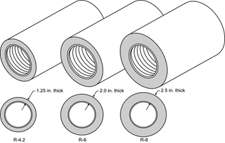
For the purpose of determining installed R-value of duct insulation based on thickness, when not an integral part of a manufacturer-labeled, insulated duct product such as vinyl flex duct, the following shall be used:
1. For duct wrap, the installed thickness of insulation must be assumed to be 75 percent of the nominal thickness due to compression.
Note: Duct installation requirements are discussed in more detail in Duct Installation Standards Section 4.4.3
The Standards set a number of mandatory measures related to duct connections and closures. These measures address both the materials and methods used for duct sealing. The following is a summary. Refer to the sections of the Standards 'listed above for additional details.
Factory fabricated duct systems must comply with the following requirements:
1. All factory-fabricated duct systems must comply with UL 181 for ducts and closure systems, including collars, connections, and splices, and be labeled as complying with UL 181. UL181 testing may be performed by UL laboratories or a laboratory approved by the Executive Director.
2. All pressure-sensitive tapes, heat-activated tapes, and mastics used in the manufacture of rigid fiberglass ducts must comply with UL 181 and UL 181A.
3. All pressure-sensitive tapes and mastics used with flexible ducts must comply with UL 181 and UL 181B.
4. Joints and seams of duct systems and their components cannot be sealed with cloth back rubber adhesive duct tapes unless such tape is used in combination with mastic and draw bands: or
5. It has on its backing the phrase "CEC approved," a drawing of a fitting to plenum joint in a red circle with a slash through it (the international symbol of prohibition), and a statement that it cannot be used to seal fittings to plenums and junction box joints.
Field –fabricated duct systems must comply with the following requirements:
1. Factory-made rigid fiberglass and flexible ducts for field-fabricated duct systems must comply with UL 181. All pressure-sensitive tapes, mastics, aerosol sealants, or other closure systems used for installing field-fabricated duct systems shall meet the applicable requirements of UL 181, UL 181A, and UL 181B.
2. Mastic sealants and mesh:
a. Sealants must comply with the applicable requirements of UL 181, UL 181A, and/or UL 181B, and be nontoxic and water resistant.
b. Sealants for interior applications must be tested in accordance with ASTM C731 and D2202.
c. Sealants for exterior applications must be tested in accordance with ASTM C731, C732, and D 2202.
d. Sealants and meshes must be rated for exterior use.
3. Pressure-sensitive tapes must comply with the applicable requirements of UL 181, UL 181A, and UL 181B.
4. Joints and seams of duct systems and their components must not be sealed with cloth back rubber adhesive duct tapes unless such tape is used in combination with mastic and draw bands: or
It has on its backing the phrase "CEC approved," a drawing of a fitting to plenum joint in a red circle with a slash through it (the international symbol of prohibition), and a statement that it cannot be used to seal fittings to plenums or junction box joints.
1. Draw bands must be either stainless-steel worm-drive hose clamps or UV-resistant nylon duct ties.
2. Draw bands must have a minimum tensile strength rating of 150 pounds.
3. Draw bands must be tightened as recommended by the manufacturer with an adjustable tensioning tool.
1. Aerosol sealants shall meet the requirements of UL 723 and be applied according to manufacturer specifications.
2. Tapes or mastics used in combination with aerosol sealing shall meet the requirements of this Section.
If mastic or tape is used to seal openings greater than 1/4 inch, the combination of mastic and either mesh or tape must be used.
Building spaces such as cavities between walls, support platforms for air handlers, and plenums defined or constructed with materials other than sealed sheet metal, duct board, or flexible duct must not be used for conveying conditioned air including return air and supply air. The practice of using drywall materials as the interior surface of a return plenum is not allowed. Building cavities and support platforms may contain ducts. Ducts installed in cavities and support platforms must not be compressed to cause reductions in the cross sectional area of the ducts. Although a HERS rater may examine this as a part of his or her responsibilities when involved in a project, the enforcement of these minimum standards for ducts is the responsibility of the building official.
Duct systems may not use cloth-back, rubber-adhesive duct tape (typical, “old fashion”, non-rated duct tape) unless it is installed in combination with mastic and draw bands. Note: mastic and drawbands alone are adequate for sealing most connections. Cloth back rubber adhesive duct tape would then only be used to hold the outer vapor barrier in place or for some other superfluous purpose. It alone is not adequate to serve as an air sealing method or as a mechanical connection.
All factory-fabricated duct systems must meet UL 181 for ducts and closure systems and be labeled as complying with UL 181. Collars, connections and splices are considered to be factory-fabricated duct systems and must meet the same requirement.
Insulated flexible duct products installed to meet this requirement must include labels, in maximum intervals of 3 ft, showing the R-value for the duct insulation (excluding air films, vapor barriers, or other duct components), based on the tests and thickness specified in §150.0(m)4 and §150.0(m)5C.
Fan systems that exhaust air from the building to the outside must be provided with back draft or automatic dampers.
Gravity ventilating systems must have an automatic or readily accessible, manually operated damper in all openings to the outside, except combustion inlet and outlet air openings and elevator shaft vents. This includes clothes dryer exhaust vents when installed in conditioned space.
Insulation must be protected from damage, including that due to sunlight, moisture, equipment maintenance, and wind but not limited to the following:
•Insulation exposed to weather must be suitable for outdoor service; for example, protected by aluminum, sheet metal, painted canvas, or plastic cover.
•Cellular foam insulation shall be protected as above or painted with a coating that is water retardant and provides shielding from solar radiation that can cause degradation of the material.
Ducts located in a concrete slab must have R-6 insulation but other issues will come into play. If ducts are located in the soil beneath the slab or embedded in the slab, the insulation material should be designed and rated for such installation. Insulation installed in below-grade applications should resist moisture penetration (closed cell foam is one moisture-resistant product). Common pre-manufactured duct systems are not suitable for below-grade installations. If concrete is to be poured directly over the ducts, then the duct construction and insulation system should be sturdy enough to resist the pressure and not collapse. Insulation should be of a type that will not compress, or it should be located inside a rigid duct enclosure. The only time that common flex ducts are suitable in a below-grade application is when a channel is provided in the slab.
Over time the outer vapor barrier of flex duct can be compromised. Therefore porous inner core flex duct is not allowed.
Duct system sealing and leakage testing is mandatory in all climate zones. Duct systems in newly constructed single family dwellings, townhouses, and multifamily dwellings are required to comply with the requirements. Alterations and additions to ducted systems in existing buildings in all climate zones are also required to comply with applicable maximum leakage criteria. Refer to Chapter 9 for more information on duct sealing and leakage testing for existing buildings.
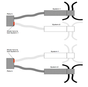
Duct Leakage Testing For Multiple Duct Systems With Common Return Ducts
If there are two or more duct systems in a building that are tied together at a common return duct, then each duct system should be tested separately, including the shared portion of the return duct system in each test. Under this scenario, the portions of the second duct system that is not being tested must be completely isolated from the portions of the ducts that are being tested, so the leakage from second duct system does not affect the leakage rate from the side that is being tested.
The diagram below represents the systems that are attached to a shared return boot or remote return plenum. In this case, the point in the return system that needs to be blocked off is readily accessible through the return grille.
The “duct leakage averaging” where both system are tested together as though it is one large system and divide by the combined tonnage to get the target leakage may not be used as it allows a duct system with more the 6% leakage to pass if the combined system’s leakage is 6% or less.
Air filtration is present in forced air systems to protect the equipment and may provide health benefits to occupants of the building. In 'addition to filtering particulates from the airstream filters add flow resistance to the forced air system, potentially lowering the efficiency of the heating/cooling equipment. Flow resistance is measured as a pressure drop at a specific airflow.
Except for evaporative coolers, any mechanical forced air heating and/or cooling system with more than 10 feet of duct must meet four sets of criteria:
1. System Design Criteria:
a) All recirculated and outdoor air passing through the heating/cooling device must first pass through the filter.
b) The system design must accommodate the pressure drop through the filter at the designed airflow. In order to accomplish this, the design airflow and the design pressure drop through the filter must be determined by the designer. The design pressure drop will determine the size and depth of the filter media required for the device (return filter grill or filter rack).
c) If the system design elects compliance utilizing the Return Duct Design alternative specified in Tables 150.0-C and 150.0-D, then the designer must assume a design filter pressure drop of 0.05 IWC at the applicable design airflow rate.
d) Replacing the filters, like for like, when they become dirty brings their resistance to airflow back to the design condition. Therefore, the filters must be located to allow access for regular service by the occupants.
e) To maintain the energy efficiency of the system it is necessary for the occupants to know which filters to select that will provide the designed airflow. Therefore, a clearly legible label, such as shown in Figure 4-6 shall be permanently placed in a location visible to a person changing the filter. As shown in Figure 4-6, the label shows the allowable maximum resistance at the airflow rate closest to the design airflow for that filter location. Figure 4-6 is an example of label for a filter location designed for 400 CFM at 0.03 IWC. Note that the standard AHRI 680 airflow values are given in 400 CFM increments. The filter media pressure drop specifications at the design airflow rates that fall between the 400 cfm increments must be determined by interpolation of the Standard 680 rating values, or by lookup methods made available by the filter media vendor or manufacturer.
|
AHRI 680 Standards Rating |
Maintenance Instructions | |
|
Airflow (CFM) |
Initial Resistance |
USE ONLY REPLACEMENT FILTERS WITH AN INTIAL RESISTANCE LESS THAN 0.032 AT 400 CFM AIRFLOW RATE |
|
400 |
0.03 | |
1. Air Filter Media Efficiency Criteria: The filter media shall be MERV 6 or better to provide protection to the equipment and to potentially provide health benefits. Filter media that provide at least 50% particle efficiency in the 3.0–10 μm range in AHRI 680 are considered to meet the MERV 6 criterion.
2. Air Filter Media Pressure Drop Criteria: To ensure airflow for efficient heating and cooling equipment operation, the installed filter media must conform to the design pressure drop specification shown in the Filter Location Label described in item 1e above.
3. Air Filter Media Labeling Criteria: The filter device must be provided with a filter media product that has been labeled by the manufacturer to disclose performance ratings that meet both the Efficiency and Pressure drop criteria described in 2, and 3 above and as shown in the Filter Location Label described in item 1e above.
Adequate airflow is critical for heating and cooling equipment efficiency. Simultaneously, the watt draw of the fan producing the airflow is a portion of the efficiency. It is important to maintain adequate airflow without expending excessive fan watts to achieve the airflow. The airflow and watt draw must be HERS verified. See Reference Residential Appendices RA3.3 for the HERS verification procedures. The prescriptive return system does not have to be HERS verified.
Except for heating only systems, systems must comply with one of the following two methods:
1. Airflow and Watt Draw measurement and determination of Fan Efficacy:
When using the Airflow (cfm/ton) and Fan Efficacy (Watt/cfm) method the following criteria must be met:
a) Provide airflow through the return grilles that is equal to or greater than 350 CFM per ton of nominal cooling capacity.
b) At the same time the fan watt draw must be less than or equal to 0.58 Watts per CFM.
The methods of measuring the watt draw are described in Reference Residential Appendix RA3.3. Three acceptable apparatuses are:
a) a portable watt meter,
b) an analog utility revenue meter, or
c) a digital utility revenue meter.
There are three acceptable methods to determine compliance with the system airflow requirement. They are described in Reference Residential Appendix RA3.3 and use an:
a) active or passive flow capture hood to measure the total airflow through the return grill(s), or
b) flow grid device(s) at the return grill(s) or other location where all the central fan airflow passes through the flow grid, or
c) fan flow meter device to perform the plenum pressure matching procedure.
The flow grid measurement device and the fan flow meter measurement device both require access to static pressure measurements of the airflow exiting the cooling coil, which utilizes a HSPP or PSPP (Section RA3.3.1.1).
The contractor must install either a hole for the placement of a static pressure probe (HSPP) or provide a permanently installed static pressure probe (PSPP) as shown in Figure 4-7 below and Reference Residential Appendix RA3.3
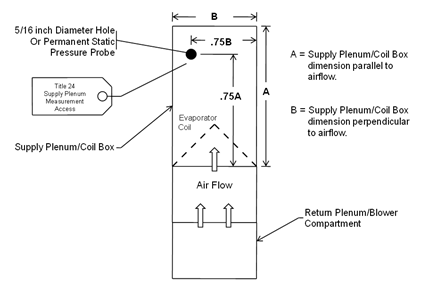
The HSPP or PSPP facilitates cooling coil airflow measurement when using devices/procedures that depend on supply plenum pressure measurements.
4. Return Duct System Design Method – This method allows the designer to specify, and the contractor to install, a system that does not have to be tested for airflow and fan watt draw. This method can be used for return systems with two returns. Each return shall be no longer than 30 feet from the return plenum to the filter grille. When bends are needed, metal elbows are desirable. Each return can have up to 180 degrees of bend and no more 90 degrees of bend can be flex duct. To use this method, the designer and installer must provide return system sizing that meets the appropriate criteria in Table 150.0-C or 150.0-D.
Studies have shown that adequate airflow is critical to the efficient operation of air conditioning systems. Section 150.0(m)13B establishes mandatory requirements that are intended to ensure adequate cooling airflow through properly sized ducts and efficient fan motors.
There are two options allowed to ensure adequate air flow; option one is to design and install the systems using standard design criteria and then have the systems airflow and fan efficacy (AF/FE) tested and third-party verified in the field. The second option is to use size the return ducts according to Tables 150.0-C and D. These tables are very simplified and very conservative (the return ducts are much larger than would normally be used). They should only be used in situations where there is a serious concern that the system will not pass the diagnostic tests for airflow and fan efficacy, such as in alterations where duct modification opportunities are limited. The first option, AF/FE testing, is always preferable, especially in new construction.
The California Green Code and the California Mechanical Code both require that residential duct systems be designed according to ACCA 'Manual D, or equivalent. If reasonable care and judgment is used in designing the duct system (both return and supply ducts) and the system is designed to reasonable parameters for airflow per ton, static pressure across the fan and friction rate, these systems should have no problem passing the diagnostic tests. Return ducts should not be sized according to Tables 150.0-C and D purely as a way to avoid the diagnostic testing. While undersized return ducts are very often the cause of poor airflow in many systems, they are only part of the overall system.
The following design guidelines will increase the chances of the system passing the AF/FE testing without sizing the return ducts according to Table 150.0-Cand D:
1. Right-size the HVAC system; if a 3-ton unit is enough to satisfy the cooling load, do not install a 4-ton unit “just to be safe”. Oversizing equipment can cause comfort problems in 'addition to excessive energy use.
2. The HVAC designer must coordinate closely with the architect and structural engineer to make sure that the ducts will fit into the home as designed.
3. Prepare a detailed mechanical plan that can be followed in the field. If deviations must occur in the field, make sure that they are coordinated with the designer and that the design is adjusted as needed.
4. Follow 'Manual D for duct sizing:
a. Make sure that the correct duct type is being used (vinyl flex, sheet metal, rigid fiberglass, etc.).
b. Make sure that all equivalent lengths and pressure drops are correctly accounted for (bends, plenum start collars, t-wyes, filters, grilles, registers, etc).
c. Select a furnace that will provide at least 400 cfm/ton at the desired static pressure of 125 to 150 Pa (0.5 to 0.6 inches w.c.).
d. Design the duct system to a static pressure across the fan of no more than 150 Pa (0.6 inches w.c.).
e. Consider upsizing the evaporator coil relative to the condenser to reduce the static pressure drop. This results in better airflow and slightly better capacity and efficiency. Manufacturers commonly provide performance data for such condenser coil combinations.
f. Consider specifying an air handler with a better quality fan motor.
5. Install a large grill area and use proper filter for the system; using a higher MERV filter than needed unnecessarily increases the static pressure.
6. Locate registers and equipment to make duct runs as short as possible.
7. Make all short-radius 90 Degree bends out of rigid ducting.
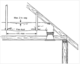
8. Install flex duct properly by: stretching all flex duct tight and cut off excess ducting, ensure the duct is not kinked or compressed, ensure flex duct is properly supported every four feet or less using one inch strapping having less than two inches of sag between supports.
Consider using better quality supply and filter grills. “Bar-type” registers have considerably better airflow performance than standard stamped-face” registers. Refer to manufacturer’s specifications and select accordingly.
Note that Standards Tables 150.0-C and D (Tables 4-10, 4-11, 4-12) only allow for one or two returns. There may be times where three returns are necessary on a single system. Furthermore, Table 150.0-D does not allow for deviation from the two sizes specified. For example, the table requires two 16” return ducts for a 3.5-ton system, but specific airflow requirements and architectural constraints may dictate something more like a 20” and a 14”. In this situation, the designer would have to rely on standard engineering principles and trust their design to pass the diagnostic tests.
Having adequate room to run properly sized ducts has always been an issue. Historically, duct systems have been sized to fit into the home at the expense of proper airflow. The performance of these systems, in terms of efficiency and capacity, has suffered greatly because of this practice; it is the intent of these standards to change these practices; the home should be designed to accommodate properly sized ducts. This requires improved coordination between the architect, structural engineer, and mechanical designer earlier in the process. This is not “best practice”, this is simply good design.
It is also important to notice that the tables require that the return grilles be sized to achieve a reasonable face velocity and static pressure drop. Return grille devices must also be labeled in accordance with the requirements in section 150.0(m)12A to disclose the grille's design airflow rate and a maximum allowable clean-filter pressure drop of 12 Pa (0.05 inches water) for the air filter media.
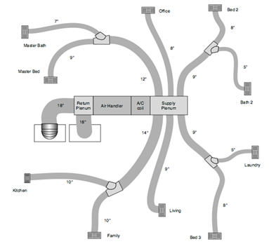
The mechanical contractor for a new home submitted the following mechanical design to the builder. It was designed using typical design specifications (400 cfm/ton at 125 Pa (0.5” wc), friction rate = 0.1, etc.). The system is has 4-ton condenser and the air handler is rated for 1600 cfm.
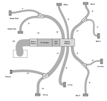
Because the builder has specified a low-end air handler, he is concerned that the system may not pass the mandatory diagnostic testing requirement for airflow and fan efficacy. The builder requests that the system be re-designed with the return ducts sized according to Table 150.0-D. The following layout is the re-designed system. The only change is that the system now has two 18” return ducts and two filter grilles sized according to Table 150.0-D, rather than a single 20” return duct and a filter grilled sized according to the manufacturer’s specifications for 1600 cfm. Note that because one of the return ducts had more than one 90 degree bend, one of the bends is required to be a metal elbow (to be insulated). The two return filters are 20”x30” each and are rated by the manufacturer to show that they have a pressure drop of less than 125 Pa ( 0.5” w.c.) at 800 cfm each.
|
System Nominal Capacity (Tons) |
Minimum Return Duct Diameter (inch) |
Minimum Total Return Filter Grille Gross Area (Inches) |
|
1.5 |
16 |
500 |
|
2.0 |
18 |
600 |
|
2.5 |
20 |
800 |
|
Two Returns | |||
|
System Nominal Tonnage |
Return 1 Minimum Duct Diameter |
Return 2 Minimum Duct Diameter |
Minimum Gross Filter Grille Face Area |
|
1.5 |
12 |
10 |
500 |
|
2.0 |
14 |
12 |
600 |
|
2.5 |
14 |
14 |
800 |
|
3.0 |
16 |
14 |
900 |
|
3.5 |
16 |
16 |
1000 |
|
4.0 |
18 |
18 |
1200 |
|
5.0 |
20 |
20 |
1500 |
The primary purpose of zoning ducted air conditioners, heat pumps, and furnaces is to improve comfort. Increased comfort is attained by having the capacity of the HVAC system (cooling or heating delivered) follow the shift in load as it changes across the house. For example, it is common for two-story homes to be too hot on the second floor in both summer and winter. Zoning has the capability of diverting more of the HVAC capacity to the area with the increased load. Another common example is a home with a significant area of west-facing and east-facing windows. In the summer, the east rooms overheat in the morning and the west rooms overheat in the afternoon.
Providing the most agreeable temperature to all the zones is comfortable, but it carries with it the distinct possibility of increased energy consumption. Since the most common home is single zoned and has only one thermostat placed near the center of the house, temperatures in the rooms distant from that thermostat will vary, sometimes significantly. If zoning is added, the more distant rooms may be conditioned to a more comfortable temperature. This increased conditioning requires more energy.
It is common for zonally controlled central forced air cooling systems to produce lower airflow through the returns thus lowering the sensible efficiency of the heating or cooling equipment. There are two primary methods by which the common multi-zoned dampered system lowers airflow: additional restriction of zoning dampers and recirculation through the air conditioner from a bypass duct. To avoid this efficiency problem, zonally controlled central forced air cooling systems utilizing a single speed air conditioner must simultaneously meet the following criteria;
1. In every zonal control mode, the system shall provide airflow through the return grilles that is equal to or greater than 350 CFM per ton of nominal cooling capacity.
2. In every zonal control mode, the fan watt draw must be less than or equal to 0.58 Watts per CFM.
The airflow and fan watt draw must be HERS verified. See Reference Residential Appendix RA3.3 for the HERS verification procedures.
Zonally controlled central forced air cooling systems with multi-speed or variable speed compressors only need to be verified to meet the above 350 CFM per nominal ton and 0.58 Watts per CFM criteria with the compressor on high speed and all zones calling for cooling.
Recent studies have shown that zoned systems (multiple zones served by a single air handler with motorized zone dampers), with or without bypass dampers, usually do not meet the AF/FE requirements when less than all zones are calling. The energy penalty that results from this is greater than the benefit of having zonal control, therefore zonal control is no longer simply assumed to be a “better than minimum” condition and there are special compliance requirements for them. Note that zonal control accomplished by using multiple single-zone systems is not subject to these requirements.
There are two choices for modeling zoned systems. One is for air conditioning condensers that have single speed compressors and the other is for condensers that have “multi-speed” compressors. Two Speed and Variable Speed Compressors are considered multi-speed. Multi-speed compressors alleviate the detrimental effects of not meeting the AF/FE when less than all zones are calling and are given special consideration when used in zoned systems. They are assumed to offset the negative impacts of zoned systems and airflow and fan efficacy testing is only required to be performed in the highest speed with all zones calling, while zoned systems with single speed compressors must be tested and pass in all operating modes.
Because zoned systems, with or without bypass dampers, are less likely to meet the AF/FE requirements when less than all zones are calling, a way is provided in the performance compliance option to take this penalty and still allow use of zone dampers. Other energy features must offset the penalty. In the performance compliance software, if the system is modeled as a zoned system with a single speed compressor, the default airflow drops to 150 CFM/ton. Note that the standard house is assumed to have an airflow of 350 CFM/ton, so there is definitely a penalty unless the user specifies a value of 350 or higher. Entering a value between 150 and 350 can lessen the penalty.
It is extremely important that the energy consultant model airflow and fan efficacy values that are reasonable and obtainable, otherwise they will fail in the field and will need to be remodeled at actual values. Energy consultants should coordinate with the HVAC designer prior to registering the Certificate of Compliance.
Note: Bypass dampers may only be installed if the Certificate of Compliance specifically states that the system was modeled as having a bypass damper.
Example:
1. A home is to be built with a zoned system (2-zones) with a single speed compressor and bypass ducts. From experience, the HVAC contractor knows that it will not be possible to meet the 350 CFM/ton requirement, but 275 CFM/ton is likely.
2. The energy consultant models the system in the proposed house with 275 CFM/ton (better than default) and 0.58 W/CFM (default). Because the standard house assumes 350 CFM/ton there is an energy penalty that must be made up with other better-than-standard features, but it is not nearly as bad as it would be at the default of 150 CFM/ton.
3. Because 275 CFM/ton is better than the default of 150, it must be tested in all zonal control modes. Because the modeled fan efficacy is the default value, it needs only to be tested with all zones calling. If a better than default value was modeled for fan efficacy it would need to be tested in all zonal control modes.
4. The home is built and the system is verified by a rater and passes at 287 CFM/ton with one zone calling, 298 CFM/ton with the other zone calling, and 372 CFM/ton with both zones calling. Note that it must still meet the mandatory requirements of 350 cfm/ton with all zones calling.
5. If this same home was to be built with a multi-speed compressor, it would only have to be tested with both zones calling whether or not it has a bypass damper, but the target airflow would be no less than 350 CFM/ton. Compliance credit can be achieved by modeling airflows greater than 350 CFM/ton and/or fan efficacies less than 0.58 watts/CFM.
|
Single-Zone Ducted Cooling Systems (Single Zone Off of a Single Air Handler) | |||
|
Compressor Type |
Mandatory Requirements for Airflow and Fan Efficacy |
Performance Compliance Option | |
|
Proposed House Defaults |
Modeled Improved Airflow and/or | ||
|
Single Speed Two Speed or (Testing Performed |
Airflow ≥ 350 CFM/ton, Fan Efficacy ≤0.58 W/CFM (Airflow and Fan Efficacy |
350 CFM/ton and 0.58 W/CFM |
Airflow ≥350 CFM/ton and/or Fan Efficacy ≤0.58 W/CFM |
|
Zoned Ducted Cooling Systems (Multiple Zones Off of a Single Air Handler) | |||
|
Compressor Type |
Mandatory Requirements for Airflow and Fan Efficacy 1 |
Performance Compliance 2 | |
|
Proposed House Defaults 3 |
Modeled Improved Airflow and/or Fan Efficacy | ||
|
Single Speed |
Airflow ≥ 350 CFM/ton and Fan Efficacy ≤ 0.58 W/ CFM
(For Prescriptive
Compliance |
150 CFM/ton and 0.58 W/CFM |
Airflow ≥ 150 CFM/ton and/or Fan Efficacy ≤ 0.58 W/CFM (Verification of
better-than default values required in all zonal control
modes. |
|
Two Speed or Variable Speed |
Airflow ≥ 350 CFM/ton and Fan Efficacy ≤ 0.58 W/ CFM (Verification Required Only on Highest Capacity and with All Zones Calling) |
350 CFM/ton and 0.58 W/CFM |
Airflow ≥ 350 CFM/ton and/or Fan Efficacy ≤ 0.58 W/CFM (Verification of
modeled |
|
1 For the Prescriptive Compliance Method, all Mandatory Requirements for airflow and fan efficacy must be met, and use of a bypass duct is not allowed. 2 For the Performance Compliance Method, all Mandatory Requirements for airflow and fan efficacy must be met, and use of a bypass duct may be specified in the compliance software input for the zoned system type. 3 The Standard House Defaults for all cases are 350 CFM/ton and 0.58 W/CFM. | |||
See Section 4.6 of this chapter for details.
A. Duct Insulation
All ducts shall either be in directly conditioned space as confirmed by field verification and diagnostic testing in accordance with RA3.1.4.3.8 (leakage to outside) or be insulated to a minimum installed level as specified by Table 150.1-A, which requires either R-6 or R-8 depending on the climate zone. (Climate zones 1-10, 12, and 13 require R-6 and climate zones 11, and 14-16 require R-8.) Since R-6 is the mandatory minimum, only the R-8 requirement can be opted out of by using the performance approach and trading off the energy penalty against some other features.
B. Central Fan Integrated (CFI) Ventilation
There is a prescriptive requirement for ducted systems that have cooling and a CFI ventilation system to have the fan efficacy verified. This can be opted out of using the performance approach.
The Standards provide credit for several compliance options related to duct design and construction.
1. System Airflow and Fan Efficacy
A performance compliance credit is available for demonstrating the installation of a high efficiency fan and duct system with better performance than the mandatory requirement of 350 cfm/ton and 0.58 watts/cfm. This credit can be achieved by selecting a unit with a high efficiency air handler fan and/or careful attention to efficient duct design. The performance compliance method allows the user’s proposed fan power to be entered into the program, and credit will be earned if it is lower than the default of 0.58 watts per CFM of system airflow. To obtain this credit, the system airflow must meet the prescriptive requirements of at least 350 CFM/ton of nominal cooling capacity. After installation, the contractor must test the actual fan power of each system using the procedure in Reference Residential Appendix RA3.3, and show that it is equal or less than what was proposed in the compliance software analysis.
The watt draw and airflow must also be verified by a HERS rater.
2. Supply Duct Location
There are three ways to achieve credit for favorable duct location when using the performance compliance method.
First, credit is available if no more than 12 LF (linear feet) of supply duct are outside conditioned space. This total must include the air handler and plenum length. This credit results in a reduction of duct surface area in the computer compliance programs. This option requires certification by the installer and field verification by a HERS rater.
The second alternative applies when 100 percent of the ducts are located in conditioned space. This credit results in eliminating the conduction losses associated with both the return and supply ducts, however, leakage rates still applies. This option requires field verification of the duct system by means of a visual inspection by a HERS rater.
Third, credit for a high efficiency duct design is available through the Diagnostic Supply Duct Location, Surface Area, and R-value compliance option, which is described below. This option requires field verification of the duct design layout drawing(s) by a HERS rater. Verified duct design, when required, will be included in the HERS Required Verification list on the Certificate of Compliance (CF-1R). This approach provides energy savings credits for having shorter duct runs, fewer ducts, ducts in beneficial locations of ductwork and other benefits of a well designed duct system.
There is no compliance credit provided for choosing a heating system such as a wall furnace, floor heater, or room heater even though those systems typically have no ducts. For these cases, the standard design in the compliance calculation uses the same type of system and also has no ducts. However, other systems, such as hydronic heating systems with a central heater or boiler and multiple terminal units, are considered central HVAC systems that are compared to a ducted system in the Standard Design. If the hydronic system has no ducts, there may be a significant energy credit through the performance method.

3. Duct Insulation
Performance credit is also available if all of the ducts are insulated to a level higher than required by the prescriptive package. If ducts with multiple R-values are installed, the lowest duct R-value must be used for the entire duct system. However, the air handler, plenum, connectors, and boots can be insulated to the mandatory minimum R-value.
As an alternative when there is a mix of duct insulation R-values, credit is available through the method described in the next section.
4. Diagnostic Supply Duct Location, Surface Area, and R-value
This compliance option allows the designer to take credit for a high efficiency duct design that incorporates duct system features that may not meet the criteria for the duct location and/or insulation compliance options described above. This method requires that the designer must enter the design characteristics of all supply ducts that are not located within conditioned space. The information required for the input to the compliance software includes the length, diameter, insulation R-value, and location of all supply ducts. This method will result in a credit if the proposed duct system is better than the standard design, which exactly meets the prescriptive insulation requirement and has supply duct surface area set at 27 percent of floor area.
In order to claim this credit, the duct system design must be documented on plans that are submitted to the enforcement agency and posted at the construction site for use by the installation persons, the enforcement agency field inspector, and the HERS rater. The duct system must be installed in accordance with the approved duct system plans, and the duct system installation must be certified by the installer on the CF2R form and verified by a HERS rater on the CF3R form. Details of this compliance option are described in Section 3.12.3 of the Residential ACM Reference Manual, and verification procedures are described in RA3.1 of the Reference Residential Appendix.
5. Buried and Deeply Buried Ducts
This compliance option also allows credit for the special case of ducts that are buried by blown attic insulation. For ducts that lie on the ceiling (or within 3.5 inch of the ceiling), the effective R-value is calculated based on the duct size and the depth of ceiling insulation as shown in Table R3-38 in the Residential ACM 'Manual. This case is referred to as “Buried Ducts on the Ceiling”. For the case of Deeply Buried Ducts, which are ducts that are enclosed in a lowered portion of the ceiling and completely covered by attic insulation, then the effective R-value allowance in the compliance calculations is R-25 when the attic insulation is fiberglass and R-31 for cellulose attic insulation. In order to take credit for buried ducts, the system must meet the verified duct design criteria described above, be diagnostically tested for duct sealing compliance by a HERS rater according to Reference Residential Appendix RA3.1, and meet the requirements for high insulation installation quality described in Reference Residential Appendix RA3.5. Verified minimum airflow (350 cfm/ton or higher if higher is specified on the CF1R) is required when a measure is selected for compliance that has a verified duct design as a prerequisite.
6. Ducts in Attics with Radiant Barriers
Installation of a radiant barrier in the attic increases the duct efficiency by lowering attic summer temperatures. Compliance credit for radiant barriers requires listing of the radiant barrier in the Special Features and Modeling Assumptions in order to aid the local enforcement agency’s inspections. Compliance credit for a radiant barrier does not require HERS rater verification.
The mandatory duct construction measures referenced in Section 4.4.1 above state that duct installations must comply with 2007 California Mechanical Code Sections 601, 602, 603, 604, 605, and the applicable requirements of the 2013 California Building Energy Efficiency Standards. Some of the highlights of these requirements are 'listed in this section along with some guidance for recommended quality construction practice.
A. Tapes and Clamps
All tapes and clamps must meet the requirements of §150.0(m).
Cloth-back rubber-adhesive tapes must be used only in combination with mastic and draw bands, or have on its backing the phrase "CEC approved," a drawing of a fitting to plenum joint in a red circle with a slash through it (the international symbol of prohibition), and a statement that it cannot be used to seal fittings to plenums and junction box joints.
B. All Joints Must Be Mechanically Fastened
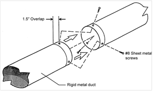
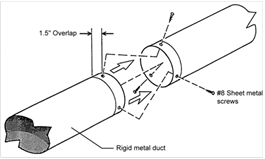
For residential round metal ducts, installers must overlap the joint by at least 1½ inch and use three sheet metal screws equally spaced around the joint (see Figure 4-10).
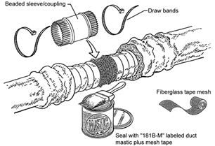
For round non-metallic flex ducts, installers must insert the core over the metal collar or fitting by at least 1 in. This connection may be completed with either mesh, mastic and a clamp, or two wraps of tape and a clamp.
For a mesh and mastic connection, the installer must first tighten the clamp over the overlapping section of the core, apply a coat of mastic covering both the metal collar and the core by at least 1 in., and then firmly press the fiber mesh into the mastic and cover with a second coat of mastic over the fiber mesh (see Figure 4-11).
For the tape connection first apply at least two wraps of approved tape covering both the core and the metal collar by at least 1 inch, then tighten the clamp over the overlapping section of the core (see Figure 4-12).
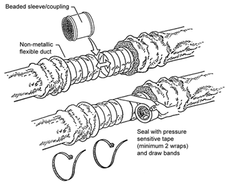
Source: Richard Heath & Associates/Pacific Gas & Electric
C. All Joints Must Be Made Airtight (§150(m)
Seal all joints with either mastic, tape, aerosol sealant, or other duct-closure system which meets the applicable requirements of UL 181, UL 181A, UL 181B, or UL 723. Duct systems shall not use cloth-back, rubber-adhesive duct tape regardless of UL designation, unless it is installed in combination with mastic and clamps. The Energy Commission has approved three cloth-back duct tapes with special butyl synthetic adhesives rather than rubber adhesive to seal flex duct to fittings. These tapes are:
1. Polyken 558CA, Nashua 558CA, manufactured by Berry Plastics Tapes and Coatings Division and
2. Shurtape PC 858CA, manufactured by Shurtape Technologies, Inc.
These tapes passed Lawrence
Berkeley Laboratory tests comparable to those that cloth-back rubber-adhesive
duct tapes failed (the LBNL test procedure has been adopted by the American
Society of Testing and Materials as ASTM
E2342-03). These tapes are allowed to be used to
seal flex duct to fittings without being in combination with mastic. These tapes
cannot be used to seal other duct system joints, such as the attachment of fittings to
plenums and junction boxes. These tapes have on their backing a drawing of a
fitting to plenum joint in a red circle with a slash through it (the
international symbol of prohibition) to illustrate where they are not allowed to
be used, and installation instructions in their packing boxes that explain how
to install them on duct core to fittings and a statement that the tapes cannot
be used to seal fitting to plenum and junction box joints.
Mastic and mesh should be used where round or oval ducts join flat or round plenums (see Figure 4-13).

All ducts must be adequately supported.
Both rigid duct and flex duct may be supported on rigid building materials between ceiling joists or on ceiling joists.
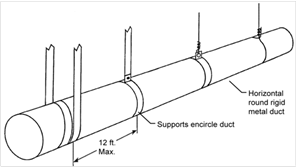
For rigid round metal ducts that are suspended from above, hangers must occur 12 ft apart or less (see Figure 4-14).
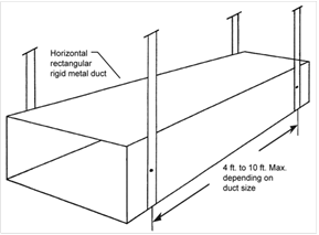
For rectangular metal ducts that are suspended from above, hangers must occur at a minimum of 4 ft to 10 ft depending on the size of the ducts (see Table 6-2-A in Appendix A of the 2007 California Mechanical Code). Refer to Figure 4-15.
For flex ducts that are suspended from above, hangers must occur at 4 ft apart or less and all fittings and accessories must be supported separately by hangers (see Figure 4-16).
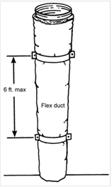
For vertical runs of flex duct, support must occur at 6 ft intervals or less (see Figure 4-17)
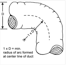
The routing and length of all duct systems can have significant impacts on system performance due to possible increased airflow resistance. The Energy Commission recommends using the minimum length of duct to make connections and the minimum possible number of turns.
For flexible duct, the Energy Commission recommends fully extending the duct by pulling the duct tight and cutting off any excess duct and avoiding bending ducts across sharp corners or compressing them to fit between framing members (see Figure 4-18). Also avoid incidental contact with metal fixtures, pipes, or conduits or installation of the duct near hot equipment such as furnaces, boilers, or steam pipes that are above the recommended flexible duct use temperature.
All joints between two sections of duct must be mechanically fastened and substantially airtight. For flex duct this must consist of a metal sleeve no less than 4 inch in length between the two sections of flex duct.
All joints must be properly insulated. For flex ducts this must consist of pulling the insulation and jacket back over the joint and using a clamp or two wraps of tape.
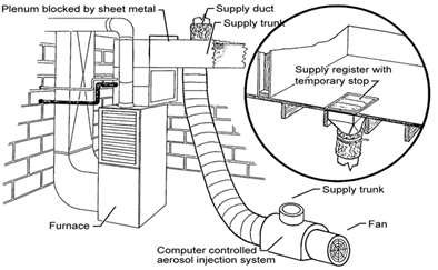
Aerosol sealant injection systems are an alternative that typically combines duct testing and duct sealing in one process. Figure 4-19 shows the computer-controlled injection fan temporarily connected to the supply duct. The plenum is blocked off by sheet metal to prevent sealant from entering the furnace. Supply air registers are also blocked temporarily to keep the sealant out of the house. Note that ducts must still be mechanically fastened even if an aerosol sealant system is used.