Construction Inspection
Reference supporting documentation as needed. It will be necessary to reference NRCC-MCH-03-E or the mechanical equipment schedules to determine the total required outdoor airflow for the system.
Indicate method and equipment used to measure airflow during the functional test (e.g. hot-wire anemometer) on the Acceptance Form. Note calibration date; calibration date must be within one year.
Check the system type (VAV or CAV) on the Acceptance Form. The following instructions apply to CAV systems.
Check that system is designed to provide a fixed minimum OSA when the unit is on, and has a means of maintaining a minimum outdoor air damper position. Minimum position is marked on the outdoor air damper. The intent is that if the damper position is moved for any reason, it can be returned to the proper position to maintain design minimum outdoor air flow requirements.
Packaged HVAC systems without an economizer will most likely have a fixed outdoor air damper that can be adjusted manually.
Small packaged HVAC systems (< 20 tons) with an economizer will most likely have a controller/actuator that will control the outside and return air dampers (for example, a Honeywell W7459A economizer control package). The economizer control package is responsible for maintaining a minimum ventilation damper position as necessary and will most likely receive operation signals from either a thermostat or through a connection to a central DDC system.
Large packaged HVAC systems (> 20 tons) will most likely have either a stand-alone economizer controller/actuator package (for example, a Honeywell W7459A) or a control package similar to a built-up system (i.e. outside and return air dampers controlled by a DDC signal). The stand-alone economizer package may receive operation signals from a thermostat, an internal DDC controller, or a central DDC system. The “built-up” style economizer will most likely be controlled by an internal DDC controller or a central DDC system. Some large package systems may also have a dedicated outdoor air damper/actuator, independent of the economizer control strategy.
Built-up HVAC system can control the outside and return dampers through a single actuator and damper linkages or through independent actuators and control signals. The control signals will most likely come from a central DDC system. Some built-up systems may also have a dedicated outdoor air damper/actuator, independent of the economizer control strategy.
Indicate the method being used to deliver outside air to the unit (e.g. duct, return air plenum). For systems where return air plenum is used to distribute outside air to a zonal heating or cooling unit, confirm that outside air supply is connected either:
•Within five ft. of the unit
•Within 15 ft. of the unit, with the air directed substantially toward the unit, and with a discharge velocity of at least 500 ft. per minute.
Confirm that pre-occupancy purge has been programmed into the system for the 1-hour period immediately before the building is normally occupied per the Standards §120.1(c)2. This is most easily accomplished by scheduling the unit to start one hour prior to actual occupancy. The purge amount must be the lesser of the minimum outdoor air rate or three complete building air changes (ACH).
Functional Testing
Follow the best practice guidelines below in order to increase accuracy of outdoor air flow measurements:
•Traverse measurements taken in supply, return or outdoor air ducts should be located in an area of steady, laminar flow. If possible, take measurements at least six to eight duct diameters away from turbulence, air intakes, bends, or restrictions.
•If using face velocity measurements to calculate outdoor air flow, care should be taken to accurately measure free area dimensions of intake.
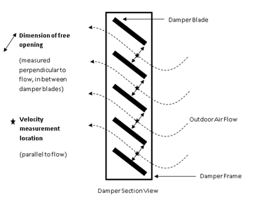
•If velocity measurements are taken at the plane of the intake between damper blades where flow is restricted (i.e. to achieve faster flows), free area should be measured as the actual open space between dampers and should not include frames or damper blades. See diagram below for illustration of free opening measurements.
•Hot wire anemometers are more appropriate than velocity pressure probes for measuring low speed flows (i.e. less than 250 feet per minute). When measuring flow with a hot wire anemometer, make sure to position the measurement device such that it is perpendicular to direction of flow.
•Take multiple measurements and average results in order to minimize effects of fluctuations in system operation and environmental conditions (i.e. wind).
Your body can serve as an obstruction to air flow and effect measurements. To increase measurement accuracy, position your body away from the intake and flow of air.
|
Step 2: Disable the air economizer if applicable and test at full supply airflow
If the system has an outdoor air economizer, force the economizer to the minimum position and stop outside air damper modulation.
For systems with an air economizer, disabling the economizer will prevent the outdoor air damper from modulating during the test due to atmospheric conditions rather than supply airflow variations. Disabling the economizer is necessary only if the system is in cooling mode and outdoor air temperature is below the economizer high limit setpoint. The economizer can be disabled in a number of ways depending on the control strategy used to modulate the outdoor air dampers:
•Use the high-limit switch by reducing the setpoint (return air value or outdoor air value if a comparative or changeover strategy, respectively, is used) below the current OSA dry-bulb or enthalpy measurement
•Disable the economizer damper control loop through software if it is a DDC system.
Verify and Document
Document the measured outdoor air reading. Document the required outdoor airflow rate found on Mechanical Plan Check document NRCC-MCH-03-E Column M, or mechanical equipment schedules. In “Testing Calculation and Results” section of the Acceptance Form, confirm that measured outdoor air flow is within 10 percent of design outdoor air flow
Outdoor air flow can be measured directly, or indirectly, in a variety of ways. Acceptable methods for measuring outdoor air flow include, but are not limited to the following techniques:
•Read the outdoor air flow value measured by an air flow monitoring station if one is installed.
•Traverse across the outdoor air duct to measure duct velocity, measure duct size, and calculate flow.
•Measure face velocity at various points across outdoor air intake, measure intake damper size, and calculate flow.
•Traverse across the supply and return ducts to calculate flow (outdoor airflow can be estimated as the difference between the supply and return airflow rates).
Step 3: Return system back to normal operating condition.
Ensure all schedules, setpoints, operating conditions, and control parameters are placed back at their initial conditions. Release any overrides on the economizer or demand ventilation controls.