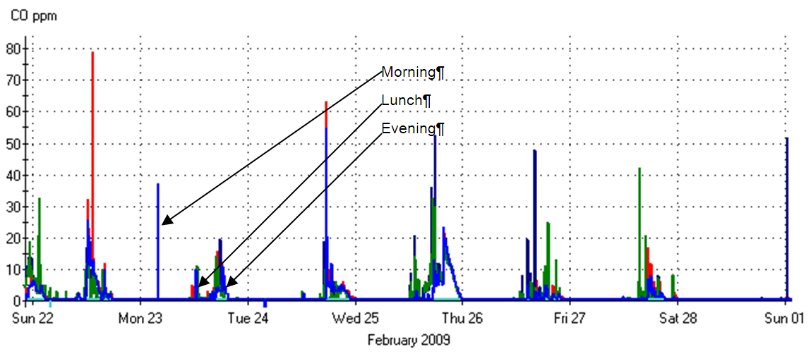
Garages exhaust systems are sized to dilute the auto exhaust at peak conditions to an acceptable concentration for human health and safety. Energy Management Control System (EMCS) of garage carbon monoxide (CO) concentrations show that in a typical enclosed garage, there are three short periods of concern: in the morning when cars enter the garage; during the lunch break when cars leave and at the end of the day, when cars leave. This mandatory measure requires modulating ventilation airflow in large enclosed parking garages based on pollutant concentrations. By modulating airflow based on need rather than running constant volume, the system will save energy and maintain a safe environment.
For garage exhaust systems with a total design exhaust rate ≥10,000 cfm, §120.6(c) requires automatic controls to modulate airflow to ≤50% of design based on measurements of the contaminant concentrations. This includes:
•Minimum fan power reduction of the exhaust fan energy to ≤ 30% of design wattage at 50% of design flow. A two speed or variable speed motor can be used to meet this requirement.
•CO concentration shall be measured with at least on sensor per 5,000 ft2 with each sensor located where the highest concentrations of CO are expected.
•CO concentration of ≤25 ppm or less as control set point at all times.
•A minimum ventilation of ≥0.15 cfm/ft2 whenever the garage is "occupied".
•The system must maintain the garage at a neutral or negative pressure with respect to adjacent occupiable areas when the garage is scheduled to be occupied.
•CO sensors shall be certified to the minimum performance requirements listed under section §120.6(c) of the Energy Standards
•Acceptance testing of the ventilation system per NA7.12.
10.2.2.1 Minimum Fan Power Reduction
Where required, the fan control must be designed to provide ≤30% of the design fan wattage at 50% of the fan flow. This can be achieved by either a two speed motor or a variable speed drive.
10.2.2.2 CO Sensor Number and Location
CO sensors (or sampling points) must be located so that each unique sensor serves an area no more than 5,000 ft2. Furthermore, the standard requires a minimum of two sensors per "proximity zone." A proximity zone is defined as areas that are separated by obstructions including floors or walls.
The typical design for garage exhaust is to have the exhaust pickups located on the other side of the parking areas from the source of makeup air. The ventilation air sweeps across the parking areas and towards the exhaust drops. Good practice dictates that you would locate sensors close to the exhaust registers or in dead zones where air is not between the supply and exhaust. Floors and rooms separated by walls should be treated as separate proximity zones.
10.2.2.3 CO Sensor Minimum Requirements
To comply, each sensor must meet all of the following requirements:
•Certified by the manufacturer to: be accurate to +/- 5%; have 5% or less drift per year; and require calibration no more than once per year.
•Be factory calibrated.
•The control system must monitor for sensor failure. If sensor failure is detected the control system must reset to design ventilation rates and transmit an alarm to the facility operators.
There are no prescriptive measures for enclosed garage exhaust.
There are no separate requirements for additions and alterations.