At-A-Glance
|
Automatic Daylighting Control Acceptance |
|
Use Document NRCA-LTI-03-A |
|
Purpose of the Test |
|
The purpose of this test is to ensure that spaces mandated to have automatic daylighting control (refer to §130.1(d)) are installed and functioning as required by the Energy Standards. |
|
Automatic daylighting controls in Primary Sidelit and Skylit Daylit Zones are mandatory if the zone includes more than 120 Watts of lighting equipment. The lighting must have multiple stages of control that meet the requirements of Table 130.1-A and §130.1(d)2Dii. Automatic daylighting controls in Secondary Sidelit Zones are prescriptive and §140.6(d) outlines their functions. |
|
Benefits of the Test |
|
The controls save energy only if they are functioning correctly. Controls passing the test provide adequate illuminance under all daylight conditions while reducing lighting power in response to daylight in the space to save a significant fraction of lighting energy. If the control leaves the space too dark, visual quality is compromised and ultimately the control will be over-ridden resulting in no energy savings. If the control leaves lights on at too high a level, the full savings from the control are not realized. |
|
Instrumentation |
|
To perform the test, it will be necessary to measure ambient light levels and validate overall power reduction. In most cases, the only instrumentation required is: |
|
Light meter (illuminance or foot-candle meter) |
|
For dimming ballasts, a default illuminance/power relationship can be used to estimate power consumption. |
|
Alternatively, the tester can choose to directly measure power or current or use the manufacturer’s dimming performance data. Additional instrumentation or data that may be needed: |
|
Hand-held amperage meter or power meter |
|
Logging light meter or power meter |
|
Manufacturer’s light versus power curve for continuous dimming and step dimming ballasts |
|
Test Conditions |
|
All luminaires in the Daylit Zone must be wired and powered. Controls installed according to manufacturer’s instructions |
|
Simulating a bright condition can be difficult; therefore, performing the test under natural sunny conditions is preferable. |
|
Document the initial conditions before testing. All systems must be returned to normal at the end of the test. |
|
Estimated Time to Complete |
|
Construction Inspection: 0.5 to 1 hour (depending on whether sensor calibration is necessary, familiarity with lighting control programming language, and availability of construction documentation – i.e. electrical drawings, material cut sheets, etc.) |
|
Equipment Test: 1 to 3 hours (depending on ability to manipulate ambient light levels, familiarity with lighting control programming language, and method employed for verifying required power reduction) |
|
Acceptance Criteria |
|
Lighting is correctly controlled so that general lighting fixtures in the Daylit Zone are controlled separately from lighting outside the Daylit zone. |
|
Photosensor has been located properly to minimize unauthorized tampering. [ §130.1(d)2Di] |
|
The photosensor is physically separated from the location where calibration adjustments are made, or is capable of being calibrated in a manner that the person initiating calibration is remote from the sensor during calibration to avoid influencing calibration accuracy. [§110.9(b)2] |
|
Sensor located and oriented appropriate to the control type and location of Daylit Zone. |
|
Under conditions where no daylight is sensed by the control, the control system increases the light output of each fixture to the design light output. This may be full output, but in a space with multi-level lighting requirements, this could be commissioned to meet the design illuminance requirements. |
|
The controlled fixtures reduce lighting power to no greater than 35 percent of full-load power under fully dimmed and/or stepped conditions. [§130.1(d)2Div] |
|
For the continuous and stepped dimming control systems, the lamps do not “flicker” at reduced light output. [§110.9(b)3], which cites the Title 20 requirements for dimming. Title 20, Section 1605.3(l)2(F)2 states, “Dimmer controls that can directly control lamps shall provide electrical outputs to lamps for reduced flicker operation through the dimming range…without causing premature lamp failure.” Because there is no standard for evaluating flicker, this is intended to refer to visible flicker. |
|
Automatic daylighting systems shall provide multi-level control capability following the guidance in Table 130.1-A. [§130.1(d)2Dii] Stepped dimming and stepped switching control systems have a minimum time delay of 3 minutes or greater before a decrease in electric lighting. [§110.9(b)2] |
|
For the stepped dimming and stepped switching control systems, the dead band between steps is sufficiently large to prevent cycling between steps for the same daylight illuminance. [§110.9(b)2] |
|
A “Reference Location” is defined that is served by the controlled lights and receives the least amount of daylight. Usually this is a location that is furthest away from the windows or skylights but is still served by the controlled lighting equipment. |
|
A “Reference Illuminance” is defined at the Reference Location – this is the illuminance from electric lighting when no daylight is available. |
|
For continuous dimming systems; Under partial daylight conditions, the combined daylight and electric lighting illuminance from continuously dimmable fixtures at the Reference Location is no less than the Reference Illuminance and no greater than 150 percent of the Reference Illuminance.[§130.1(d)2Diii&iv] |
|
When stepped lighting controls dim or turn off a step, the combined daylight and electric lighting illuminance from stepped dimming or stepped switching fixtures at the Reference Location is no less than the Reference Illuminance and no greater than 150 percent of the Reference Illuminance after the electric light is fully diminished. [§130.1(d)2Diii&iv] |
|
Potential Issues and Cautions |
|
Check fixture circuiting while access to wiring is relatively easy (i.e. while lift is available or before obstructions are installed). |
|
Simulating bright conditions and achieving proper luminance to perform the test can be difficult. Therefore, it is recommended that the test be performed under natural bright light conditions. |
|
For the stepped dimming and switching control systems, it is acceptable to shorten the time delay while performing the tests, but the time delay must be returned to normal operating conditions when the test is complete (at least 3 minutes). |
A. Test Application
Newly Constructed and Additions/Alterations: Applies to properly located controls, field calibrated and set to appropriate lighting levels.
Preparing for Sampling:
•All photocontrols serving more than 5,000 ft² of daylit area shall undergo functional testing.
•Photocontrols that are serving smaller spaces may be sampled as follows:
o For buildings with up to five (5) photocontrols, all photocontrols shall be tested.
o For buildings with more than five (5) photocontrols, sampling may be done on spaces with similar sensors and cardinal orientations of glazing.
- Sampling shall include a minimum of 1 photocontrol for each group of up to 5 additional photocontrols.
- If the first photocontrol in the sample group passes the functional test, the remaining building spaces in the sample group also pass.
- If the first photocontrol in the sample group fails the functional test, the rest of the photocontrols in the group shall be tested.
•If any tested photocontrol fails the functional test, it shall be repaired, replaced or adjusted until it passes the test.
Definition of the Daylit Zones
The following information on the definitions of the Daylit Zones are only needed if the designer has not documented on the plans the Daylit Zones or if the as built location of windows and skylights do not correspond to the Daylit Zones on the plans. When the plans are incorrectly documenting the Daylit Zones, it is the tester’s responsibility to identify the problem and inspect and test the system based upon the as-built configuration of the Daylit Zones. It is recommended that this is conducted in consultation with the designer.
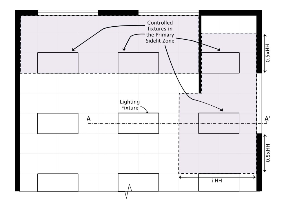
•Primary Sidlit Daylit Zone is the combined Primary Sidelit Daylit Zone for each window without double counting overlapping areas. The floor area for each Primary Sidelit Daylit Zone is directly adjacent to vertical glazing below the ceiling with an area equal to the product of the Primary Sidelit Daylit Zone width and the Primary Sidelit Daylit Zone depth.
•Primary Sidelit Daylit Zone width is the width of the window plus, on each side, the smallest of:
o 0.5 times the window head height.
o The distance to any 6 foot or higher permanent vertical obstruction.
o The distance to any Skylit Daylit Zone.
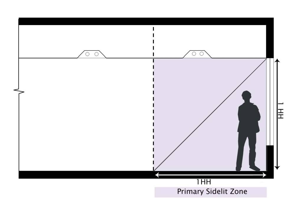
•Primary Sidelit Daylit Zone depth is the horizontal distance perpendicular to the glazing that is the smaller of:
o One window head height.
o The distance to any 6 foot or higher permanent vertical obstruction.
o The distance to any Skylit Daylit Zone.
•Secondary Sidlit Daylit Zone is the combined Secondary Sidelit Daylit Zone for each window without double counting overlapping areas. The floor area for each Secondary Sidelit Daylit Zone is directly adjacent to Primary Sidelit Daylit Zone with an area equal to the product of the Secondary Sidelit Daylit Zone width and the Secondary Sidelit Daylit Zone depth.
•The Secondary Sidelit Daylit Zone width is the width of the window plus, on each side, the smallest of:
o 0.5 times the window head height.
o The distance to any 6 foot or higher permanent vertical obstruction.
o The distance to any Skylit Daylit Zone.
•The Secondary Sidelit Daylit Zone depth is the horizontal distance perpendicular to the glazing that begins from one window head height, and ends at the smaller of:
o Two window head heights.
o The distance to any 6 foot or higher permanent vertical obstruction.
o The distance to any Skylit Daylit Zone.
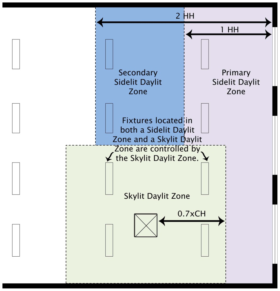
•Skylit Daylit Zone is the combined Skylit Daylit Zone under each skylight without double counting overlapping areas. The daylight area under each skylight is bounded by the rough opening of the skylight, plus horizontally in each direction the smallest of:
o 70 percent of the floor-to-skylight or skylight well height.
o The distance to any permanent partition or permanent rack that is taller than 50 percent of the distance from the floor to the bottom of the skylight and oriented in a direction to cause a shadow.
When the partitions fall within the floor plan rough opening of the skylight, they do not cause shadowing that reduces the overall coverage of the skylight. In these cases, the coverage area should not be limited by the partition.
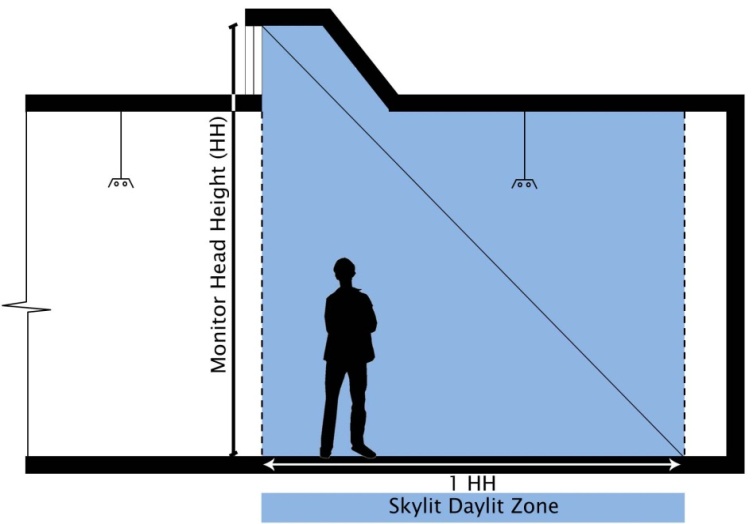
Figure 13-4: Side view of Primary and Secondary Sidelit Zones
•Clearstory or monitor windows have a different coverage pattern than the traditional skylight and are treated as windows, but the Daylit Zone is considered a Skylit Daylit Zone. The Skylit (Monitor) Zone depth under each monitor window is defined from the plane of the monitor window, extending towards the back by the smaller of:
o 100 percent of the floor-to-head height of the monitor.
o The distance to any permanent partition or permanent rack that is not directly below the monitor well, whichever is taller than fifty percent of the distance from the floor to the bottom of the ceiling, and is oriented such that it will cast a substantial shadow to the back.
•The Skylit (Monitor) Daylit Zone width is the width of the monitor window plus the smaller of:
o 50 percent of the floor-to-head height of the monitor window.
o The distance to any permanent partition or permanent rack that is not directly below the monitor well, whichever is taller than fifty percent of the distance from the floor to the bottom of the ceiling, and is oriented such that it will cast a substantial shadow to the side.
o In buildings with no partitions, the Skylit Daylit Zone under skylights is the footprint of the skylight plus in each direction 70 percent of the ceiling height or halfway to the next skylight, whichever is less. This is shown in Figure 13-5:
Figure 13-5: Elevation View of Skylit
Daylit Zone under Skylight (no interior partitions)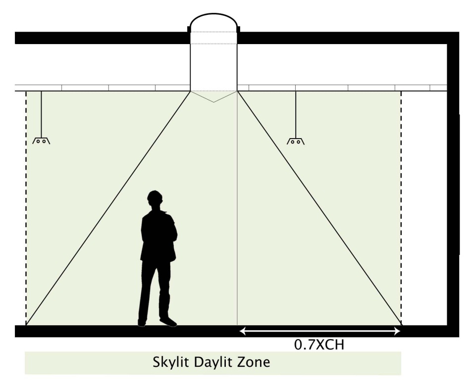
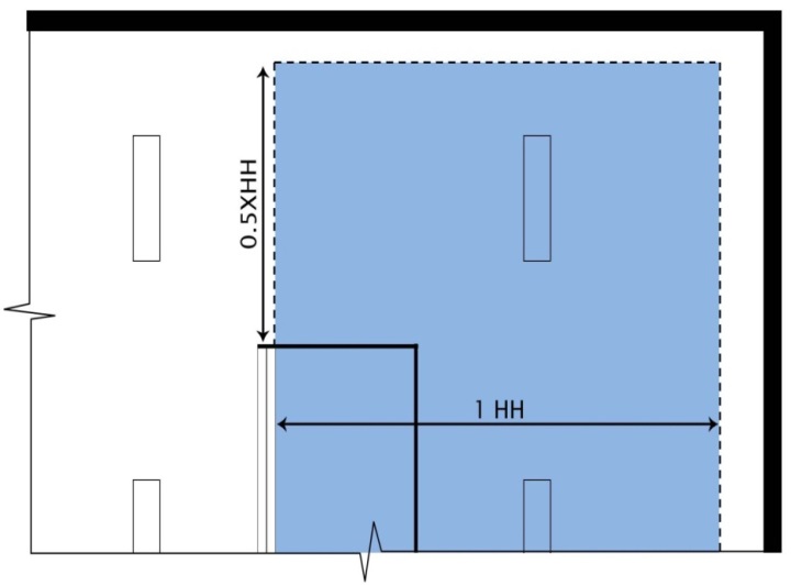
If there are permanent partitions or racks below the skylight, the partitions may block portions of the full extent of the Skylit Daylit Zone. There are two conditions that must occur for a partition to reduce the Daylit Zone. A partition must be greater than 50 percent of the distance from the floor to the bottom of the skylight (or monitor window), and is not directly below the skylight or monitor well, and the partition must be oriented so that the object creates a shadow beyond it. This is illustrated in Figure 13-7 below.
Figure 13-7: Elevation View of Skylit
Daylit Zone under Skylight (with interior partitions) 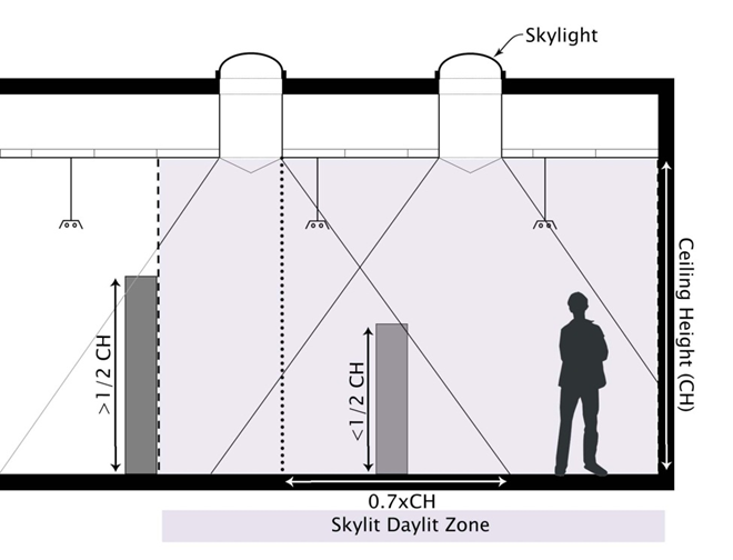
Figure 13-8: Plan View of Skylit Daylit Zone under Skylights (with interior partitions)
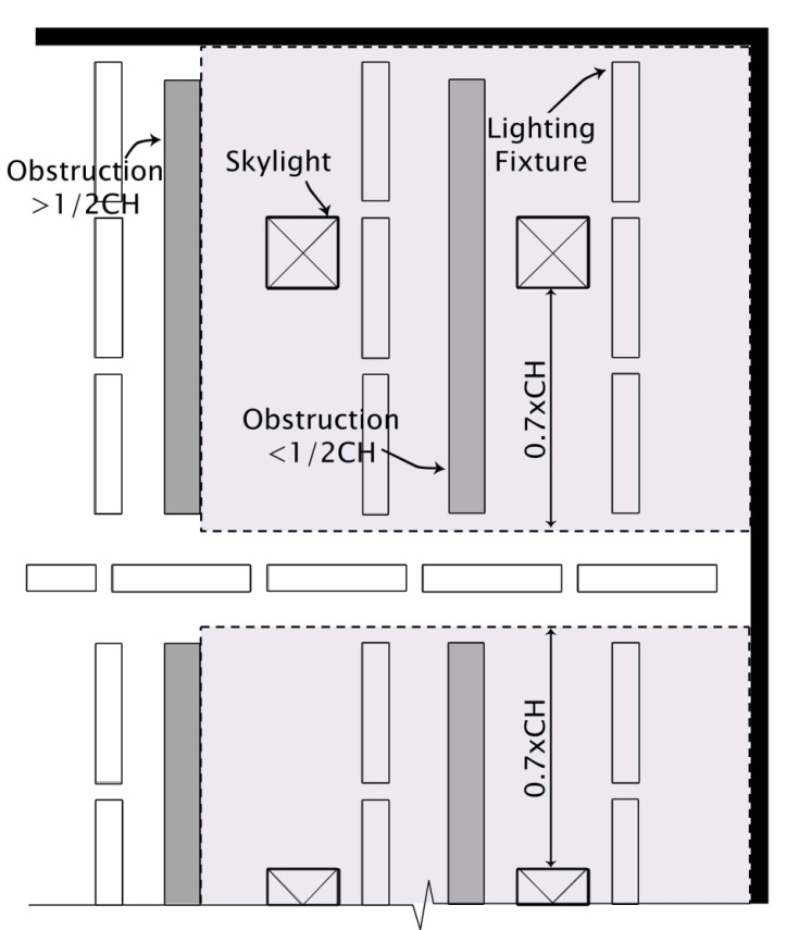
Figure 13-9: Example of Skylit Daylit Zone
under Skylight
(with interior partitions where one partition is not
considered ‘blocking’)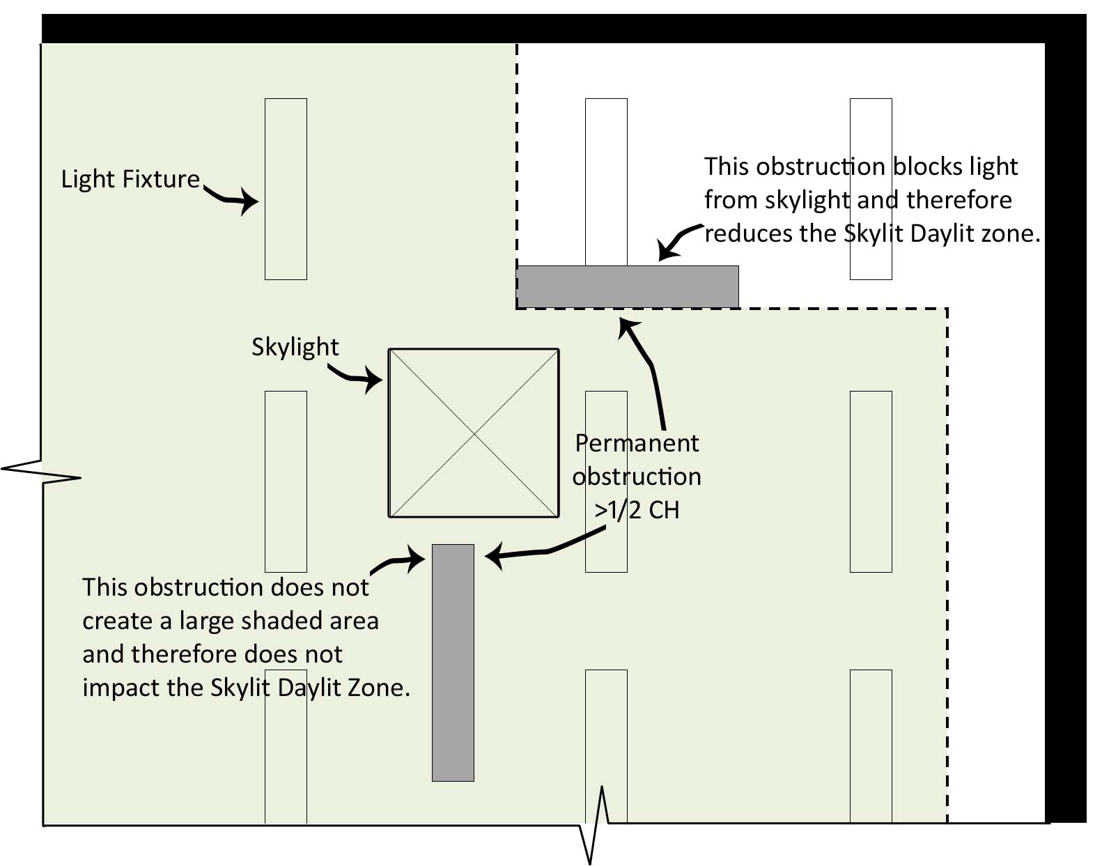
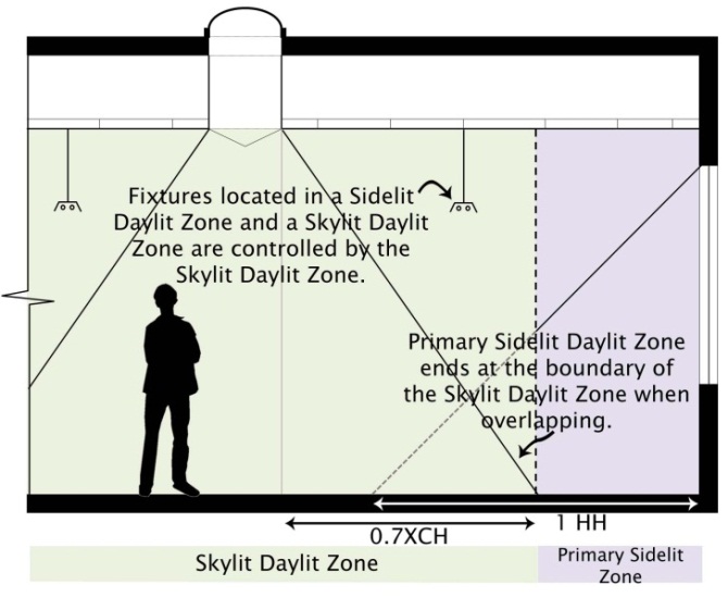
•Hierarchy of Zones. In situations where Zones overlap, there is a hierarchy of Zone assignment so that there is no condition where the lighting equipment is considered in more than a single Zone. The hierarchy is as follows:
1. Skylit (including monitor windows or clearstories).
2. Primary Sidelit.
3. Secondary Sidelit.
The lighting equipment is assigned based on which Zone it is within or touching, so a light fixture that is partially within two different Zones will be placed in the higher Zone, per the above hierarchy.
B. Construction Inspection
1. Purpose of the Test
The purpose of this construction inspection is to ensure that the daylighting controls that are installed in the space meet the location, specification and accessibility requirements per §110.9(b)2; and to ensure that control devices have been certified to the Energy Commission in accordance with the applicable provision in §110.9.
2. Criteria for Passing the Test
The system must pass all six key criteria identified in Document NRCA-LTI-03-A Part I:
•All Daylit Zones are clearly marked on plans or drawn on as-built drawings.
•All Daylit Zone type and control type is clearly identified on the Document.
•Sensors and controls are appropriate for the particular requirements of the daylighted area and intended functions, and are located in appropriate locations per §110.9(b)2 and §130.1(d).
•Sensor and control setpoints are documented by the installer.
•Daylighting controls only control those luminaires that are in the daylighted area for which they are intended and luminaires in Sidelit Daylit Zones are controlled separately from luminaires in Skylit Daylit Zones.
•Daylighting controls have been certified to the Energy Commission in accordance with §110.9(a)3.
2. How to Conduct the Test and Fill the Document
Step 1: Daylit Zones Shown on Plans
The building plans are required to have a drawing of the extents of the Daylit Zones when controls are required or controls are used to obtain lighting control credits.
If the plans do not have the Daylit Zones indicated for the spaces containing photocontrols, draw the Daylit Zones on the as-built plans and attach to the acceptance test documents. A copy should be sent to the designer and the building owner.
When there are more than one type of Daylit Zones present and thus daylighting control systems exist on site, these should be clearly marked on the plans, and also noted on the document. The user is able to specify up to three (3) systems per document.
For buildings with several daylighting controls, one may sample the controls for Acceptance Testing. When sampling, clearly note it on the documents. A separate sheet should be attached to the document with names of the other controls and systems that are being represented by the three systems on the document. At least one daylighting control shall be tested for each Daylit Zone category (Skylit, Primary Sidelit, and Secondary Sidelit).
Step 2: System Information
There are three types of Daylit Zones:
•The Skylit Daylit Zones under skylights,
•The Primary Sidelit Daylit Zones adjacent to within one window head height of the vertical glazing, and
•The Secondary Sidelit Daylit Zones, located between the corresponding Primary Sidelit Daylit Zone and two window head heights from the vertical glazing.
The window head height is the distance from the floor to top of the window. This is summarized in the Section titled “Definition of Daylit Zones.”
1. Controlled Lighting Wattage:
•Note the total wattage of luminaires that are controlled by the given control system. If there are multiple controls systems (A, B, C on the document), identify controlled wattage separately for each type of control system.
•When the Primary Sidelit Daylit Zone or Skylit Daylit Zone in a room (enclosed space) includes greater than 120 watts of lighting equipment, all general lighting in this daylighted area is required to be controlled by an automatic daylighting control.
•General lighting is defined as lighting that is “designed to provide a substantially uniform level of illumination throughout an area, exclusive of any provision for special visual tasks or decorative effect.” Linear fluorescent troffers and pendants, high and low bay luminaires and other non-directional light sources are considered general lighting.
•When automatic daylighting controls are required in Primary Sidelit Daylit Zones, these lights must be separately controlled from the Secondary Sidelit Daylit Zone.
•The photocontrol must control only those fixtures in the daylighted area. A luminaire is considered to be in the Daylit Zone if any part of the luminaire touches the defined Daylit Zone. With long pendant fixtures that cross into Daylit Zone, the lamps that touch the Daylit Zone must be controlled separately from those not in the Daylit Zone.
•Luminaires and lamps that touch more than one Daylit Zone follow this hierarchy for assignment; 1. Skylit, 2. Primary Sidelit, 3. Secondary Sidelit.
•Controls for Sidelit Daylit Zones are required to be separate from controls for Skylit Daylit Zones.
Note: Identifying whether fixtures are controlled by a given sensor or control may be difficult without operating the system. For this reason, it may be better to conduct this portion of the construction inspection in conjunction with the functional performance test.
The controlled fixtures are readily identified by noting which fixtures are turned on and off or are dimming in response to the no daylight and full daylight functional performance tests.
2. Control Type:
•Identify the type of luminaire control used in each of the control systems identified in the document. There are three types of controls identified on the document:
•Continuous dimming controls are controls that alter the output of lamps in at least 10 steps.
•Step dimming controls alter the output of lamps in less than 10 steps (typically up to four steps between on and off).
•Step switching controls turns lamps or groups of lamps on and off without any steps between on and off.
•Stepped switching controls are able to provide multi-level lighting by having more than one group of lamps being controlled. Partial light output (and partial power consumption) of the stepped switching lighting system is provided by turning some of the lamps on.
3. Design Footcandles:
Note the design footcandles for general illumination in the Daylit Zone served by each of the control systems identified in the document. If the design light level is not known for a given control system, clearly identify that it is unknown.
Step 3: Sensors and Controls
•Loop Type and Sensor Location: Verify that all photosensors have been properly located. Per §130.1(d)2D, an individual photosensor must be located so that it is not readily accessible. This placement is intended to make it difficult to tamper with the photosensor. Photocontrols that are part of a wallbox occupant sensor do not comply and shall not be considered an acceptable photocontrol device.
•The photosensor must be located so that can readily sense daylight entering into the daylit area.
•Closed loop sensors – sensors that measure both daylight and the controlled electric light shall be located within the area served by the controlled lighting.
•Open loop sensors – sensors that mostly measure the daylight source shall be outdoors or near a skylight or window and typically oriented toward the window or skylight.
Control Adjustment Location: Adjustments to the controls must be “readily accessible” to authorized personnel or are in ceilings that are 11 ft. or less.
•Readily accessible means that one can walk up to the control adjustment interface and access it without climbing ladders, moving boxes etc. The control can be in a locked cabinet to prevent unauthorized access. Controls that can be adjusted via a wireless handheld device would also qualify as being readily accessible.
•Controls that are mounted in ceiling cavities must be within 2 ft. of the ceiling access and the ceiling access must be no more than 11 ft. above the floor.
Step 4: Control System Documentation
Verify that the setpoints, settings and programming on each of the control system device has been documented and provided by the installer.
Step 5: Daylit Zone Circuiting
Verify that the luminaires in the Daylit Zone are controlled separately from those outside the Daylit Zone. Further, verify that the luminaires in daylit areas near windows are circuited separately from the luminaires in daylit areas under skylights. Verify the correct Daylit Zone category for luminaires following the spacing requirements stated in the above sections. The Skylit Daylit Zone takes top priority in situations where Daylit Zones overlap, then Primary Sidelit, and finally, Secondary Sidelit. Finally, nte that separate circuiting is not a requirement and not necessary with digital systems.
Step 6: Daylighting Control Device Certification
Verify that installed daylighting controls have been certified to the Energy Commission in accordance with the applicable provisions of §110.9:
•Automatic Daylighting Control Devices
•Interior Photosensors
Verify that model numbers of all daylighting controls are listed on the Energy Commission database as “Certified Appliances & Control Devices” by visiting:
http://www.energy.ca.gov/appliances/database
C. Functional Testing
There are two separate functional performance tests that are specific to the type of control being tested. The first test is suitable for continuous dimming systems and the second test is for step dimming or step switching controls (both described in detail below).
•Continuous dimming controls are controls that alter the output of lamps in at least 10 steps.
•Step dimming controls alter the output of lamps in less than 10 steps (typically up to four steps between on and off).
•Step switching controls turns lamps or groups of lamps on and off without any steps between on and off.
•Stepped switching controls are able to provide multi-level lighting by having more than one group of lamps being controlled. Partial light output (and partial power consumption) of the stepped switching lighting system is provided by turning some of the lamps on.
The tests for stepped switching and stepped dimming controls are combined as the discrete steps of light output render them sufficiently similar for functional testing.
Note: Many of the steps in these acceptance tests can be conducted while setting up the controls according to manufacturer’s instructions. Read these tests prior to conducting equipment set-up and bring the documents along while conducting set-up. This way you can conduct the equipment set-up and perform the acceptance test at the same time.
1. Sampled functional performance testing of systems smaller than 5,000 ft²
All photocontrols serving a Daylit Zone more than 5,000 ft² shall undergo functional testing. Photocontrols that are serving Daylit Zones less than 5,000 ft² are allowed to be tested on a sampled basis. The sampling rules are as follows:
•For buildings with up to five (5) photocontrols, all photocontrols shall be tested.
•For buildings with more than five (5) photocontrols, sampling may be done within spaces with similar sensor types, cardinal orientations of glazing, and Daylit Zone categories (Skylit, Primary Sidelit, and Secondary Sidelit).
•If the first photocontrol in the sample group passes the functional test, the remaining building spaces in the sample group also pass, with the provision that the basic function of the rest are observed to appear to be functional.
•If any photocontrol in the sample group fails, it shall be repaired or replaced as required until it passes the test and all photocontrols in the sample group must be tested.
•This process shall repeat until all photocontrols have passed the test or the photocontrol tested passes on the first testing.
2. Zone Illuminated by Controlled Luminaires
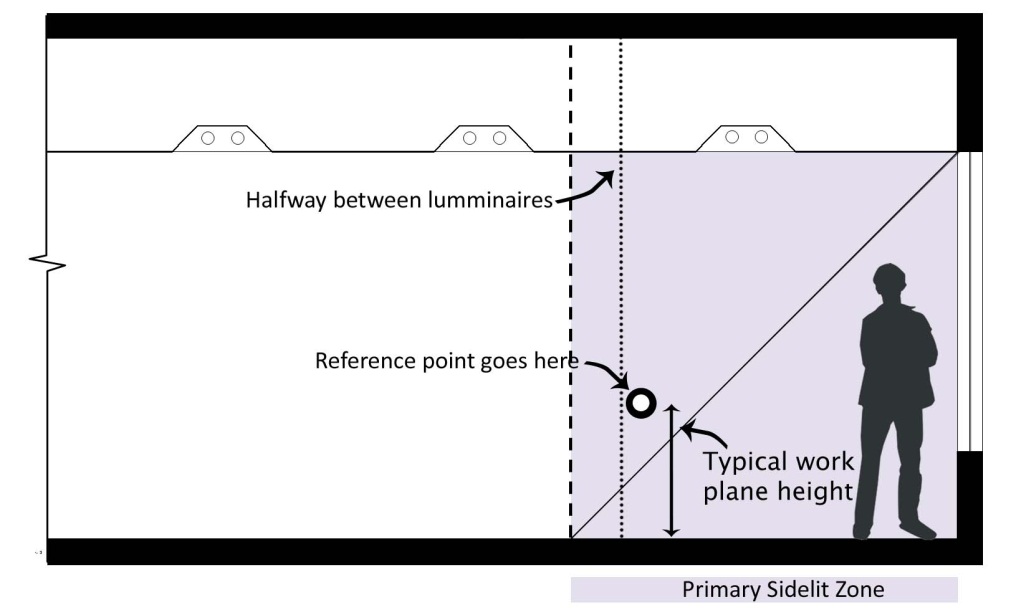
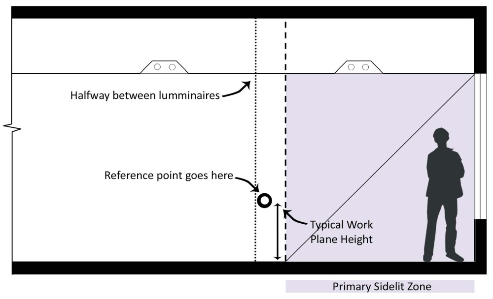
The functional performance requirements for both continuous dimming and step (dimming or switching) controls call for “all areas being served by controlled lighting” being between 100 and 150 percent of the night time electric lighting illuminance. Without checking all points in the zone served by controlled lighting, verifying that the requirements are met at a worst case location somewhat removed from windows or skylights is sufficient. This location is called the “Reference Location” and is described in the functional performance tests in the next section.
Also note that the “zone illuminated by the controlled lighting” is not the same as the Primary Sidelit, Secondary Sidelit or Skylit Daylit Zones. The Sidelit and Skylit Daylit Zones define which luminaires must be controlled. Luminaires in the Sidelit or Skylit Daylit Zones must be controlled by automatic daylighting controls, and luminaires outside of these areas must not be controlled by the same automatic daylighting control.
The edge of the zone illuminated by the controlled lighting is halfway between the controlled lighting and the uncontrolled lighting. The only situation this is not so, is when the edge of the daylit zone is defined by a partition. The zone illuminated by the controlled luminaires can be smaller than the daylit area when the uncontrolled luminaires are near the edge of the daylit area [see example (a) of Figure 13-11]. Alternatively the zone illuminated by the controlled luminaires can be larger than the daylit area when the controlled luminaires are near the edge of the daylit area [see example (b) of Figure 13-11].
Continuous Dimming Control Systems – Functional Performance Test
1. Purpose of the Test:
This test is for continuous dimming systems with more than 10 steps of light output from the controlled lighting. For instructions on acceptance testing of other systems with less than 10 steps of control, skip this section and proceed to the next section Stepped Switching or Stepped Dimming Control Systems Functional Performance Test.
2. Criteria for Passing the Test
Key criteria for passing the functional performance test are:
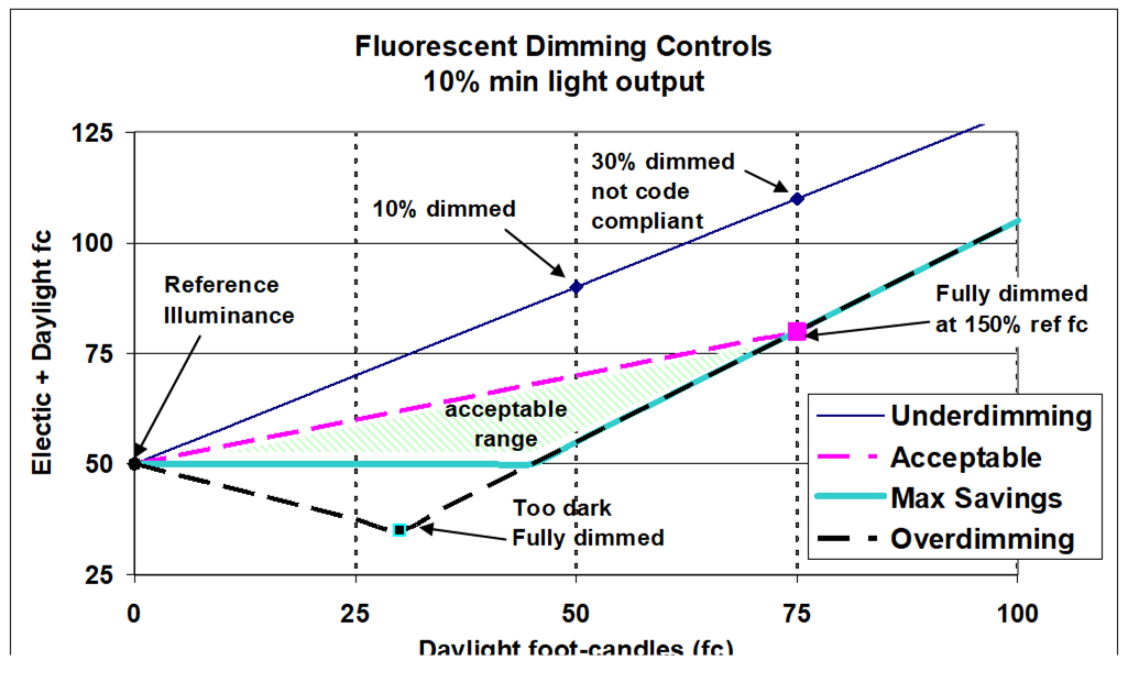
•When there is NO daylight in the space, all controlled luminaires are within a reasonable distance from design output or full rated output and power consumption.
•Where there is full daylight in the space (daylight alone provides adequate illumination in space), luminaires in the daylit zone use less than 35 percent of full rated power. Accommodation is made for a task tuned lighting system in this process.
•When there is partial daylight (between 60 and 95 percent of the design illuminance) in the space, the luminaires in the daylit zone are dimmed so that the illuminance at the reference location is between the design illuminance and 150 percent of the design illuminance.
•The shaded triangle labeled “acceptable range” in Figure 13-12, illustrates the range of total illumination levels that will comply with this requirement.
3. How to Conduct the Test and Fill the Document
Step 1: Identify Reference Location
The Reference Location is the location in zone served by the controlled lighting that is receiving the least amount of daylight.
The Reference Location will be used for light level (illuminance in foot-candles) measurements in subsequent tests. The Reference Location is used in testing the daylighting controls so that it can be assured that all occupants in the zone served by the controlled lighting always have sufficient light.
The Reference Location can be identified using either the illuminance method or the distance method. The illuminance method is preferred.
Illuminance Method:
•Turn OFF controlled lighting and measure daylight illuminances within zone illuminated by controlled luminaires. Note that the zone illuminated by the controlled luminaires is not necessarily the same as the daylit area. See the Section above with the heading “Zone Illuminated by Controlled Luminaires.”
•Identify the Reference Location; this is the location with lowest daylight illuminance in the zone illuminated by controlled luminaires. Note that zone illuminated by controlled luminaires is not necessarily the same as the Daylit Zone. See the note above with the heading “Zone Illuminated by Controlled Luminaires”
•Turn controlled lights back ON.
Distance Method:
Identify the Reference Location; this is the location within the zone illuminated by controlled luminaires that is furthest way from daylight sources. Note that zone illuminated by controlled luminaires is not necessarily the same as the Daylit Zone. See the note above with the heading “Zone Illuminated by Controlled Luminaires”. Note that this method is not likely to produce the most consistent result and should be avoided in preference to the illuminance method above.
Step 2: “No Daylight” Test
The purpose of the “no daylight” test is to provide a baseline light level, the Reference Illuminance, against which the test professional will be comparing the performance of the system during daylit conditions. This test is also verifying that the control is providing adequate light at night.
When conducting this test, the other lights in the space should be turned off. Simulate or provide conditions without daylight. This condition can be provided by any of the applicable methods:
Conducting this part of the test at night, or
Leave a logging light meter at the Reference Location(s) overnight. The logger should be collecting data on an interval no longer than 1 minute per reading, taking reading on even shorter intervals is recommended. You must disable any occupant sensor or time clock to use this approach.
Closing blinds or covering fenestration so that very little daylight enters the test zone. Very little daylight is less than 1 fc for warehouses and less than 5 fc for all other occupancies. For open loop systems only, one may cover the photosensor to simulate no daylight conditions. Covering the sensor is not allowed for closed loop controls to assure that the control will work correctly at night as well during the day.
When daylight from the space is not possible to exclude during this test, the Reference Illuminance can be calculated by subtracting the daylight illuminance from the combined illuminance (footcandles) of the electric lighting and daylight. The daylight illuminance is measured by turning off the controlled lights.
Reference Illuminance (Preferred Method):
Document the Reference Illuminance (fc) – the horizontal electric lighting illuminance (footcandles) at the Reference Location identified in Step 1.
This measurement is taken by an illuminance sensor (light meter) 30 inches above floor level. The sensor should be facing upwards. Mounting the light meter on a tripod is recommended so that consistent measurements are taken. Try not to shade the meter with your body while taking measurements.
Power Measurement (Optional):
If a current or power measurement is going to be used in Step 3 to show power reduction under fully dimmed conditions, collect full load current or power. To best do this, ensure that the lighting system does not have any task tuning or lumen maintenance adjustments in the control system.
This is not normally necessary for systems with dimming fluorescent ballasts. It is easier just to compare electric lighting illuminance. For more details see Step 3 “Full Daylight Test.”
Full load rating or measurement:
The full load rating can be obtained a number of ways:
One may also choose to manipulate the calibration adjustments (remember to write down the setting first before changing them) to obtain full light output from the controlled lighting. This might require turning the setpoint very low and turning the high limit very high. It may also require that the control system does not have active task tuning or lumen maintenance adjustments incorporated into the control system. Discuss your approach with the control manufacturer with their recommendations to get full light output. If the photosensor is accessible, covering the photosensor is a way to assure full light output.
If you cannot eliminate all daylight from the area or other electric light from other luminaires: Turn the controlled lighting on and off. The difference in light level will be the contribution of the controlled lighting.
If one is measuring power or amps, the rated amps can be directly measured under this condition. Verify that only the controlled lights in the daylit area are being measured. You may want to disconnect and re-energize this circuit to assure you are measuring what you intend.
The rated amps or power from the manufacturer’s cut-sheet is also sufficient.
Step 3: Full daylight test.
Simulate or provide bright conditions so that the illuminance (fc) from daylight only at the Reference Location identified in Step 1 is greater than 150 percent of the Reference Illuminance (fc) measured at this location during the ‘no daylight’ test documented in Step 2.
Simulating a bright condition can be accomplished by opening all shading devices to allow natural daylight into the space.
If natural conditions are not adequate at the time of the test, shine a bright flashlight or other light source onto the photosensor.
Temporarily change the setpoint to a very low value for the duration of this test. Then return the setpoint to its normal setting.
Verify and document
Lighting power reduction is at least 65 percent under fully dimmed conditions. Lighting power reduction can be determined as follows:
Dimming fluorescent lighting is deemed to reduce power by 65 percent when the controlled electric light output is reduced by 75 percent or greater from rated output. With a task tuned lighting system, the dimming fluorescent lighting is deemed to reduce power by 65 percent when the controlled electric light output is reduced by 69 percent or greater.
Dimming metal halide is deemed to have reduced power by 44 percent when light output is reduced by 75 percent.
One method of attaining the 65 percent power reduction with dimming metal halide systems is to turn off half of the luminaires and dim the other half.
The power reduction in higher performing dimming ballasts can be estimated from lighting output reductions if it is accompanied with a manufacturer’s ballast cut sheets containing a ballast input power vs. percent light output curve or table.
Power reduction can be directly measured using either a power meter or an ammeter. The percent reduction in current will be a sufficient representation of the percent reduction in power. Dimming fluorescent lighting is deemed to reduce power by 65 percent when the controlled electric load is reduced by 65 percent or greater from full connected load. With a task tuned lighting system, the dimming fluorescent lighting is deemed to reduce power by 65 percent when the controlled electric load is reduced by 56 percent or greater.
The system lighting power reduction is given by the following relations:
Reduction = Fraction of lights turned off + Fraction of lights dimmed x power reduction of the dimmed lamps
Where,
The power reduction of dimmed lamps =
(Rated power – dimmed power) / rated power
Example: When a metal halide dimming system dims half of the lamps and the other half of the lamps are automatically switched off. The System Power Reduction, SPR is:
SPR = 0.5 + (0.5 x 0.44) = 0.72 or 72 percent
This is above the 65 percent threshold.
•Verify that only luminaires in appropriate Daylit Zone are affected by daylight control.
1 Primary Sidelit Daylit Zones have to be separately controlled from Secondary Sidelit Daylit Zones, and vice versa. They may use a single sensor for implementation, but the control response formulas must be distinct.
2 Sidelit Daylit Zones have to be separately controlled from Skylit Daylit Zones.
The daylighting control assigned to a specific Daylit Zone shall not control fixtures beyond the Zone, with the exception of Primary and Secondary Sidelit Daylit Zones in which both share a boundary.
•Verify that light output is stable with no discernible flicker.
The intent of this requirement is to ensure the lights do not flicker because occupants may override the system if light flicker is an annoyance. Flicker refers to a rapid fluctuation in light output that can be detected by the human eye.
Step 4: Partial daylight test.
Simulate or provide bright conditions where illuminance (fc) from daylight only at the Reference Location is between 60 and 95 percent of Reference Illuminance (fc) documented in Step 2. These partial daylight illuminance conditions can be achieved by:
•Scheduling the test so that daylight conditions are within this fairly broad range of illuminances.
Verify and document
1 Measured combined illuminance of daylight and controlled electric lighting (fc) at the Reference Location
2 Verify this measured illuminance is no less than the Reference Illuminance documented in Step 2, and
3 Verify this measured illuminance is no greater than 150 percent of the Reference Illuminance (fc) documented in Step 2
This test assures that the control does not over-dim and leave people with insufficient light in the Reference Location of the Zone served by the controlled lights. This also makes sure that the control does not under-dim thus misses energy savings opportunities. By setting the upper bound of illuminance to 150 percent of the Reference Illuminance, this leaves plenty of room for non-optimal configurations, adaptation compensation, and variations in the sensor field of view.
Note: Adaptation compensation is a control strategy that accounts for people needing less light at night. When someone walks into a store late at night from a parking lot with light levels at 1 fc they may not need or want light at 50 fc. Thus a store may decide to have higher light levels during the day than at night. This protocol would allow daytime light levels that are 50 percent higher than the night time light levels.
Stepped Switching or Stepped Dimming Control Systems Functional Performance Test
1. Purpose of the Test:
This functional performance test is for systems that have no more than 10 discrete steps of control of light output. For instructions on how to test systems with more than 10 steps of control including those systems where the dimming appears to be continuous proceed to the previous section: Continuous Dimming Control Systems - Functional Performance Test.
If the control has three steps of control or less, conduct the following tests for all steps of control. If the control has more than three steps of control, testing three steps of control is sufficient for showing compliance.
If these tests are to be conducted manually (spot measurements) it is recommended to test the system with the time delay minimized or otherwise overridden so the test can be conducted more quickly.
These tests can also be conducted with a logging (recording) light meter. In this case, the time delay should be left on so the recorded data also shows the results of the time delay. In the logging method, one would print out a plot of the day’s illuminance at the Reference Location and annotate the plot showing where each stage of lighting had shut off and how the light level just after shutting off for each stage is between the Reference Illuminance and 150 percent of the Reference Illuminance.
2. Criteria for Passing the Test:
Key criteria for passing the functional performance test are:
•When there is NO daylight in the space, all controlled luminaires are at rated lighting output and power consumption.
•When there is full daylight in the space (daylight alone provides greater than 150 percent of the Reference Location illumination in space), luminaires in the daylit zone use less than 35 percent of rated power.
•When there is some daylight in the space, the luminaires in the daylit zone are switched or dimmed appropriately.
•If the control has three steps of control or less all steps of control are tested. If the control has more than three steps of control, testing three steps of control is sufficient for showing compliance.
•There is a time delay of at least 3 minutes between when daylight changes from little daylight to full daylight and the luminaire power consumption reduces through dimming.
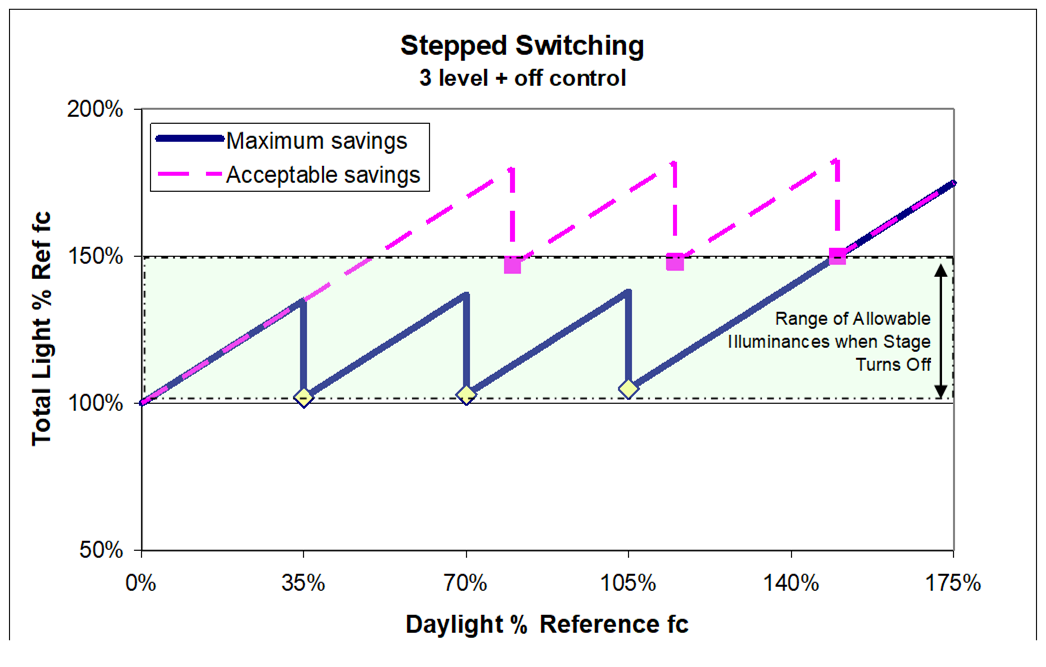
As shown in Figure 13-13, the acceptance tests will confirm that the total illuminance at the reference location is between 100 and 150 percent of the reference illuminance. The highlighted points on the plots (squares and diamonds) indicate the daylight and total light levels at the reference location just after the lights on each stage of control have turned off or dimmed.
The plot of the “Maximum savings” control illustrates how this control maximizes the possible lighting energy savings without under-lighting the space. Systems with lower control setpoints than the “Maximum savings” control would not be compliant as the control would under-light the space during certain times of the day and would likely lead to the control being disabled.
The plot of the “Acceptable savings” control shows how this control maintains light levels above the reference illuminance for all daylight hours but still saves enough energy to be minimally compliant. Systems with higher setpoints than those of the “Acceptable savings” control would not be compliant.
3. How to Conduct the Test and Fill the Document
Step 1: Identify Reference Location
The Reference Location is the location in Zone served by the controlled lighting that is receiving the least amount of daylight. The Reference Location will be used for light level (illuminance in foot-candles) measurements in subsequent tests. The Reference Location is used in testing the daylighting controls so that it can be assured that all occupants in the Zone served by the controlled lighting always have sufficient light.
If lighting controls are staged so that one stage is closer to the daylight source, identify a minimum daylighting location for each stage of control.
If lighting controls are NOT staged based on distance to the daylight source, select a single minimum daylighting location representing all stages of the control. This minimum daylighting location for each stage of control is designated as the Reference Location for that stage of control and will be used for illuminance measurements in subsequent tests.
The Reference Location can be identified using either the illuminance method or the distance method.
Illuminance Method:
•Turn OFF controlled lighting and measure daylight illuminances within zone illuminated by controlled luminaires
•Identify the Reference Location; this is the location with lowest daylight illuminance in the zone illuminated by controlled luminaires.
•Turn controlled lights back ON.
Distance Method:
•Identify the Reference Location; this is the location within the zone illuminated by controlled luminaires that is furthest way from daylight sources. Note that zone illuminated by controlled luminaires is not necessarily the same as the Daylit Zone. See the note above with the heading “Zone Illuminated by Controlled Luminaires”. Note that this method is not likely to produce the most consistent result and should be avoided in preference to the illuminance method above.
Step 2: ‘No Daylight’ Test
Simulate or provide conditions without daylight for a stepped switching or stepped dimming control system. This condition can be provided by any of the applicable methods:
•Conducting this part of the test at night.
•Leave a logging light meter at the Reference Location(s) overnight, (the logger should be collecting data on an interval no longer than 1 minute per reading, taking reading on even shorter intervals is recommended). The occupant sensor or time clock system must be overridden for this approach to work.
•Closing blinds or covering fenestration so that very little daylight enters the zone you are testing, (very little daylight is defined as less than 1 fc for warehouses and less than 5 fc for all other occupancies).
•Cover the photosensor.
If the control is manually adjusted (not self-commissioning), make note of the time delay and override time delay or set time delay to minimum setting. This condition shall be in effect through Step 4.
When conducting this test, the other lights in the space should be turned off.
Verify and document
•Automatic daylight control system turns ON all stages of controlled lights.
•Document the Reference Illuminance (fc) – the horizontal electric lighting illuminance (footcandles) at the Reference Location identified in Step 1.
•This measurement is taken by an illuminance sensor (light meter) 30 inches above floor level. The sensor should be facing upwards. Mounting the light meter on a tripod is recommended so that consistent measurements are taken. Try not to shade the meter with your body while taking measurements.
•When it is not possible to exclude daylight from the space during this test, the Reference Illuminance can be calculated by subtracting the daylight illuminance from the combined illuminance (footcandles) of the electric lighting and daylight. The daylight illuminance is measured by turning off all nearby lights including the controlled lights.
•For step dimming controls, calculate power consumption using manufacturer-provided cut-sheet information or measure the power consumption.
•(Optional) If a current or power measurement is going to be used in Step 3 to show power reduction under full daylight conditions, collect full load current or power. Note: no power measurements are needed for step switching systems.
Step 3: Full Daylight Test
Simulate or provide bright conditions so that the illuminance (fc) from daylight only at all of the Reference Location(s) identified in Step 1 is greater than 150 percent of the corresponding Reference Illuminance(s) documented in Step 2.
•Simulating a bright condition can be accomplished by opening all shading devices to allow natural daylight into the space.
•If natural conditions are not adequate at the time of the test, shine a bright flashlight or other light source onto the photosensor.
•Temporarily change the setpoint to a very low value for the duration of this test then return the setpoint to its normal settings.
Verify and document
•Lighting power reduction of controlled luminaires is at least 65 percent of rated power consumption. Methods of doing this include:
•For switching systems, at least 2/3s of the lamps are turned off.
Note: for switching systems, power measurement is unnecessary. The fraction of power reduction is easily estimated without taking power measurements. The fraction of power reduction is calculated by counting the number of lamps that are switched off versus the total number of lamps providing general lighting in the Daylit Zone.
•For stepped dimming systems, either calculate the fraction of rated power at the dimming stage from the ballast manufacturer’s cut sheet or calculate from power measurements taken during the No daylight and full daylight tests.
•If using the manufacturer’s cut-sheet, wattage at full output and dimmed amounts are given. A copy of this cut-sheet must be attached to the acceptance testing form. Count the number of dimmed fixtures and those fully turned off to calculate reduced power operation. If calculated power is 35 percent or less of the power calculated in Step 2, this meets the criteria.
•If using measured power or current draw of the controlled fixtures. If measured power or current draw is 35 percent or less the value from Step 2, the criteria is met.
•Only luminaires in Daylit Zones (Skylit Daylit Zone, Primary Sidelit Daylit Zone and Secondary Sidelit Daylit Zone) are affected by daylight control.
•Automatic daylight control system reduces the amount of light delivered to the space relatively uniformly as per §130.1(d).
•All lights are dimmed.
•Alternating lamps, alternative fixtures or alternating rows of fixtures are turned off.
Step 4: Partial daylight test
For each stage of control that is tested in this step, the control stages with lower setpoints than the stage tested are left ON and those stages of control with higher setpoints are dimmed or controlled off. This step is repeated for up to three stages of control between full on and full dimmed or full off condition.
One of the stages selected for testing should reduce power draw between 30 and 50 percent of system rated power (for switching systems a stage that turns off between a third and a half of the lamps). That test will help confirm that the system can reduce power between 30 and 50 percent.
Simulate or provide moderately bright conditions so that each control stage turns on and off or dims. Methods to do this include:
•Adjusting blinds or shades. Note that the time delay needs to be disabled to use this method. Slowly increase the daylight illuminance until a stage of lighting turns off. Make note of the total combined and electric lighting illuminance at the Reference Location just after the stage of lights turned off. Continue increasing daylight illuminance by opening blinds or shades for at least two more stages of control
•Light logging. Leave a logging light meter at the Reference Location(s) for one day with a bright afternoon. Note that the occupant sensor system must be disabled to use this method. The logger should be collecting data on an interval no longer than 1 minute per reading, taking reading on even shorter intervals is recommended.
•Open loop ratio method. If the system is open loop (the light sensor senses mainly daylight) the amount of daylight in the space is presumed proportional to the amount measured at the open loop sensor. Adjust setpoint until control turns lights off or are dimmed. Make note of daylight illuminance at the reference location and control setpoint or sensor illuminance display.
If the sensor measures 300 fc while there is 30 fc of daylight at the Reference Location, the ratio of Sensed fc to fc at Reference Location is 10 to 1. If the needed daylight illuminance is 50 fc a setpoint of 500 sensed fc is deemed to provide control at 50 fc.
Verify and document the following for each tested control stage:
The tests do not need to be performed for more than three stages of control.
•The total daylight and electric lighting illuminance level measured at its Reference Location just after the stage of control dims or shuts off the stage of lighting.
•The total measured illumination shall be no less than the Reference Illuminance measured at this location during the No Daylight test documented in Step 2.
•The total measured illumination shall be no greater than 150 percent of the Reference Illuminance.
•The control stage shall not cycle on and off or cycle between different levels while daylight illuminance remains constant.
Cycling is prevented by having a dead band that is sufficiently large. The dead band is the difference between the setpoint for turning the control stage ON and the setpoint for turning that control stage OFF. The dead band must be greater than the sensor measurement of the light level steps to prevent cycling of lamps on and off.
For manual testing, control time delay is overridden so it is quickly apparent if the dead band is set appropriately.
•If the dead band is too small, the system will cycle. This will be an annoyance and may lead to the system being disabled by irritated occupants.
•If the dead band is set too large, the system will not save as much energy as it could.
•To manually set a dead band, adjust the daylight level or the setpoint so that the setpoint matches the daylight illuminance. Reduce the dead band until the system cycles and then increase the dead band until the system stops cycling.
Step 5: Verify time delay
•Verify that time delay automatically resets to normal mode within 60 minutes of being over ridden.
•Set normal mode time delay to at least 3 minutes.
•Confirm that there is a time delay of at least 3 minutes between the time when illuminance exceeds the setpoint for a given dimming stage and when the control dims or switches off the controlled lights.
Note: One can force a change of state and by dropping the setpoint substantially and timing how long it takes for the control stage to switch off or dim.