At-A-Glance
|
NA7.5.1 Variable Air Volume Systems Outdoor Air Acceptance |
|
Use Document NRCA-MCH-02-A |
|
Purpose of the Test |
|
This test ensures the provision of adequate outdoor air ventilation through the variable air volume air handling unit at two representative operating conditions. The test consists of measuring outdoor air values at maximum flow and at or near minimum flow. The test verifies the introduction of a minimum volume of outdoor air, in accordance with §120.1(b)2, into the air handling unit and is within 10 percent of the required volume when the system is in occupied mode at these two conditions of supply airflow. Perform this test in conjunction with NA7.5.6 (NRCA-MCH-07-A) Supply Fan Variable Flow Controls Acceptance test procedures to reduce the overall system testing time as both tests use the same two conditions of airflow for their measurements. Related acceptance tests for these systems include: |
|
NA7.5.4 Air Economizer Controls. |
|
NA7.5.5 Demand Control Ventilation (DCV) Systems (if applicable). |
|
NA7.5.6 Supply Fan Variable Flow Controls |
|
Instrumentation |
|
Performance of this test will require measuring outdoor air flow. When the system includes an airflow monitoring system (AFMS) on the outdoor air, then it may be used for the measurements if it has a calibration certificate or is field-calibrated. The instrumentation needed to perform the task may include, but is not limited to: |
|
An airflow measurement probe (for example, hot-wire anemometer or velocity pressure probe), or |
|
A watch or some equivalent device to measure time in minutes |
|
Test Conditions |
|
The test needs an override of the normal control operations. The control system of the air handling unit and zone controls must be complete, including: |
|
Supply fan capacity control (typically a variable speed drive). |
|
Air economizer control. |
|
Minimum outdoor air damper control. |
|
Zone airflow control (including zone thermostats and VAV boxes). |
|
Installed systems shall be ready for system operation, including: |
|
Duct work |
|
VAV boxes. |
|
Control sensors (temperature, flow, pressure, and so forth). |
|
Electrical power to air handling unit and control system components. |
|
Completion of air handling unit start-up procedures, per manufacturer’s recommendations. |
|
Document the initial conditions before executing system overrides or manipulation of the set points and schedules. At the end of the test, return all systems to normal. Reference NRCC-MCH-03-E or the mechanical equipment schedules to determine the total required outdoor airflow for the system. |
|
Estimated Time to Complete |
|
Construction inspection: 0.5 hours to 2 hours, depending on complexity and difficulty in calibrating the “system” controlling outdoor air flow. |
|
Functional testing: 1 to 3 hours, depending on the type of zone control and the number of zones. |
|
Acceptance Criteria |
|
Field- or factory-calibrated sensor controlling outdoor air flow with documentation attached. |
|
Measured outdoor airflow reading is within 10 percent of the total value found on the Energy Standards Mechanical Plan Check document NRCC-MCH-03-E, under the following conditions: |
|
Minimum system airflow or 30 percent of total design flow |
|
Design supply airflow |
|
Potential Issues and Cautions |
|
Use caution when performing test during winter months in cold climates. Since outdoor airflow must remain constant as supply fan flow is reduced, total supply flow can approach 100 percent outdoor air. Be sure that all freeze protection and heating coil controls are functioning before performing test. |
|
Coordinate test procedures with the controls contractor who may assist with manipulation of the BAS to achieve the desired operating conditions. |
|
Ensure disabling of economizer and demand controlled ventilation controls before performing the test. |
A. Test Application
•Newly constructed and additions/alterations: Applies only to new variable air volume (VAV) systems
•Constant air volume systems outdoor air acceptance
•Newly constructed and additions/alterations: Applies only to new constant air volume (CAV) systems
B. Construction Inspection
1. Refer
2. ence the supporting documentation as needed. Reference NRCC-MCH-03-E or the mechanical equipment schedules to determine the total required outdoor airflow for the system.
3. Indicate method and equipment used to measure airflow during the functional test (for example, hot-wire anemometer) on the acceptance document. Note calibration date; calibration date must be within one year.
4. Check the system type (VAV or CAV) on the acceptance document. (The following instructions apply only to VAV systems.)
5. Check that the sensors used to control outside air (OSA) flow is either factory- or field-calibrated. Attach the calibration certificate or field calibration results to the acceptance test document NRCA-MCH-02-A.
6. Check that a fixed minimum damper set point is not controlling OSA. The field technician shall review the operation sequences to ensure the system performs dynamic control of minimum outdoor air and reviews the installation to confirm all of the devices of that sequence are present.
7. Indicate the dynamic control method used to control OSA in the system. There are several means to dynamically control minimum OSA for VAV systems, and many ways for the designer to specify an active ventilation air control “system” intended to maintain a constant outdoor air flow rate as supply fan flow rate decreases.
For example, an installed flow station measures outdoor air flow rate and modulates the outdoor air dampers accordingly. Or perhaps dampers are modulated to maintain a constant differential pressure across a dedicated outdoor air damper assembly. The sensors, equipment, and control strategy necessary to achieve the desired control shall be calibrated as a “system,” regardless of the control method of the outdoor airflow.
8. Indicate the method used to deliver outside air to the unit (for example, duct, return air plenum). For systems using return air plenums to distribute outside air to a zonal heating or cooling unit, confirm that outside air supply connects either:
•
•Within 5 feet of the unit.
•Within 15 feet of the unit, with the air directed substantially toward the unit, and with a discharge velocity of at least 500 feet per minute.
9. Confirm the system program includes a preoccupancy purge for the 1-hour period immediately before normal occupancy of the building per §120.1(c)2. This confirmation is most easily accomplished by scheduling the unit to start one hour before actual occupancy. The purge amount must be the lesser of the minimum outdoor air rate or three complete building air changes (ACH).
C. Functional Testing
Air handling systems with a dedicated fan providing ventilation air to the unit are exempt from measuring ventilation airflow at minimum and maximum supply airflow conditions. An independent ventilation air fan will deliver a constant minimum outdoor air volume to the air handling unit regardless of the speed of the supply fan. Therefore, the only verification needed for this system type would be to measure the actual CFM delivered by the dedicated ventilation air fan.
Follow the best practice guidelines below to increase accuracy of outdoor air flow measurements:
•Traverse measurements taken in supply, return or outdoor air ducts shall be located in an area of steady, laminar flow. If possible, take measurements at least six to eight duct diameters away from turbulence, air intakes, bends, or restrictions.
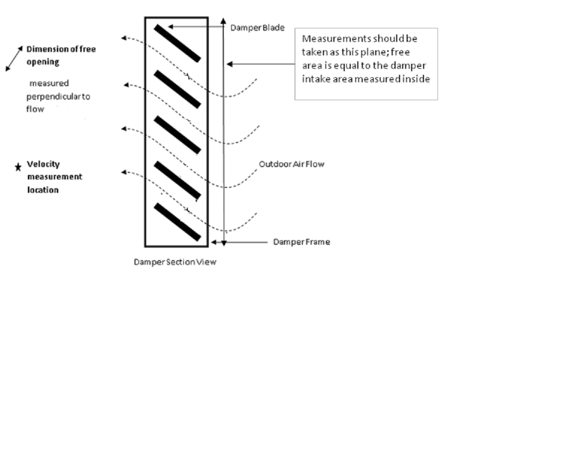
•When using face velocity measurements to calculate outdoor air flow, take particular care to accurately measure free area intake dimensions.
•When taking velocity measurements at the plane of the intake between damper blades where flow is restricted (that is, to achieve faster flows), free area shall be measured as the actual open space between dampers and should not include frames or damper blades. See Figure 13-2 below for illustration of free opening measurements.
 |
•Hot wire anemometers are more appropriate than velocity pressure probes for measuring low-speed flows (that is, less than 250 feet per minute). When measuring flow with a hot wire anemometer, make sure to position the measurement device perpendicular to the flow direction.
•Take multiple measurements and average results to minimize effects of fluctuations in system operation and environmental conditions (such as wind).
Your body can obstruct air flow and affect measurements. To increase measurement accuracy, position your body away from the intake and airflow.
Step 1: Disable demand control ventilation, if applicable.
Step 2: Verify unit is not in economizer mode. Disable the air economizer, if applicable.
For systems with an air economizer, disabling the economizer will prevent the outdoor air damper from modulating during the test due to atmospheric conditions rather than supply airflow variations. Disabling the economizer is necessary only if the system is in cooling mode and outdoor air temperature is below the economizer high-limit set point. The economizer can be disabled in several ways, depending on the control strategy used to modulate the outdoor air dampers:
•Use the high-limit switch by reducing the set point (return air value or outdoor air value if a comparative or changeover strategy, respectively, is used) below the current OSA dry-bulb or enthalpy measurement.
•Disable the economizer damper control loop through software if it is a DDC system.
Step 3: Modify VAV boxes to achieve full design airflow.
The intent is to measure outdoor air flow when the system is operating at or near the design airflow condition, or maximum airflow at full cooling. This point is provided along with the minimum operating point to test the minimum OSA control at either end of the control range. There are a number of ways to achieve design airflow including:
•Override all space temperature cooling set points to a low temperature (for example, 60°F cooling) that will force the VAV boxes into full cooling (may be accomplished by a global command or it may have to be done per box).
•Command all VAV boxes to design flow position (may be accomplished by a global command or it may have to be done per box).
•Set the VAV box minimum flow set point to be the same as maximum flow set point (may be accomplished by a global command or it may have to be done per box).
Verify and Document:
•Document the supply airflow at full cooling on the acceptance document.
•Document VFD speed; VFDs should be at or near 60Hz.
•Document the measured outdoor air reading. Document the required outdoor airflow as found on mechanical plan check document NRCC-MCH-03-E Column M, or mechanical equipment schedules. In the “Testing Calculation and Results” section of the acceptance document, confirm that measured outdoor air flow is within 10 percent of design outdoor air flow rate.
•Outdoor air flow can be measured directly, or indirectly, in a variety of ways. Acceptable methods for measuring outdoor air flow include, but are not limited to the following techniques:
o Read the outdoor air flow value measured by an air flow monitoring station, if one is installed.
o Traverse across the outdoor air duct to measure duct velocity, measure duct size, and calculate flow.
o Measure face velocity at various points across outdoor air intake, measure intake damper size, and calculate flow.
o Traverse across the supply and return ducts to calculate flow (outdoor airflow can be estimated as the difference between the supply and return airflow rates).
•Document time for OSA damper to stabilize after the VAV boxes open on the acceptance document. Confirm that dampers stabilize within 5 minutes. The intent is to ensure the proportional-integral-derivitative (PID) control loops are tuned properly.
Step 4: Drive all VAV boxes to either the minimum airflow, full heating airflow, or 30 percent of total design airflow.
The intent is to measure outdoor air flow when the system is operating at or near a minimum flow condition (for example, full heating). This point is provided along with the design point to test the minimum OSA control at either end of the control range. If the system has an airflow monitoring station (AFMS), it will test the accuracy of that AFMS at the lowest velocity, namely the least accurate point.
There are several ways to force the VAV boxes to a minimum position depending on the building automation system capabilities and control strategies used, for example:
Override all space temperature set points to a wide range (e.g. 60°F heating and 90°F cooling) that will force the VAV boxes into the dead band (may be accomplished by a global command or it may have to be done per box).
Command all VAV boxes to minimum flow position (may be accomplished by a global command or it may have to be done per box).
Set maximum flow set point to be the same as minimum flow set point (may be accomplished by a global command or it may have to be done per box).
An alternative method is to manually adjust the VFD until the system airflow is at the desired condition. If the VAV boxes are in control they will open up as you are doing this, so you need to provide some time (about 5 minutes) to allow the system to settle. Although this is acceptable for testing OSA, this would not meet the requirements of NA7.5.6 Supply Fan Variable Flow Controls for testing the stability of the pressure control loop. These two tests should be done concurrently to minimize cost.
Verify and Document:
•Document the supply airflow on the acceptance document.
•Document VFD speed.
•Document the measured outdoor air reading. In the “Testing Calculation and Results” section of the acceptance document, confirm that measured outdoor air flow is within 10 percent of design outdoor air flow rate found on mechanical plan check document NRCC-MCH-03-E Column M, or mechanical equipment schedules. The methods provided earlier for conducting field airflow measurements also apply here.
•Document time for OSA damper to stabilize after the VAV boxes open on the acceptance document. Confirm that dampers stabilize within 5 minutes. The intent is to ensure the PID control loops are tuned properly.
Step 5: Return system back to normal operating condition.
Ensure all schedules, set points, operating conditions, and control parameters are placed back at the initial conditions. Release any overrides on the economizer or demand ventilation controls.