5.6 HVAC Zone Level Systems

This group of building descriptors relate to HVAC systems at the zone level. There is not a one-to-one relationship between HVAC components in the proposed design and the standard design since the standard design system is determined from building type, size, and heating source. The applicability of each building descriptor for each of the 11 standard design systems is indicated in tables under the building descriptor standard design rules. Additions and alterations should follow the same requirements stated for new construction proposed designs and new construction standard designs; unless otherwise noted in the descriptor.

5.6.1    Space Temperature Control

Space Thermostat Throttling Range

Applicability

All thermal zones

Definition

The number of degrees that the room temperature must change to cause the HVAC system to go from no heating or cooling (i.e., space temperatures floating) to full heating or cooling

Units

Degrees Fahrenheit (°F)

Input Restrictions

The prescribed value is 2°F. (This is equivalent to a +/- 1°F temperature tolerance around the heating and cooling setpoint.) No input is needed and the prescribed value may not be overridden.

Standard Design

Same as the proposed design

Standard Design:

Existing Buildings


Space Temperature Schedule

Applicability

All thermal zones

Definition

An hourly space thermostat schedule

Units

Data structure: temperature schedule

Input Restrictions

Prescribed

The schedule group is specified for the given space type in Appendix 5.4A, and the schedule values are specified in Appendix 5.4B.

Standard Design

Schedules in the standard design shall be identical to the proposed design, unless operable windows are present in the thermal zone. If operable windows are present, the heating schedule shall be overridden to 50°F and the cooling schedule shall be overridden to 90°F whenever the operable window schedule for that hour indicates that the window(s) are open.

Standard Design:

Existing Buildings


5.6.2    Terminal Device Data

Terminal Type

Applicability

All thermal zones

Definition

A terminal unit includes any device serving a zone (or group of zones collected in a thermal zone) that has the ability to re-heat or re-cool in response to the zone thermostat. This includes:

     None (the case for single zone units)

     VAV box

     Series fan-powered VAV box

     Parallel fan-powered VAV box

     Dual-duct mixing box (constant volume and VAV)

     Reheat coil (constant volume systems)

Units

List (see above)

Input Restrictions

As designed

Standard Design

Table 16 specifies the HVAC terminal device for each of the standard design systems. See Section 5.1.2 for a summary of the HVAC mapping.

Standard Design:

Existing Buildings


Table 13: Standard Design HVAC Terminal Devices

Standard Design System

Terminal Type

System 1 – PTAC

None

System 2 – FPFC

None

System 3 – PSZ-AC

None

System 5 – Packaged VAV with Reheat

VAV Box

System 6 – VAV with Reheat

VAV Box

System 7 – SZVAV

None

System 9 – Heating and Ventilation

None

System 10 – CRAH

None

System 11 – CRAC

None

System 12 – LAB

None

System 13 – Kitchen

None

5.6.3    Terminal Heating

This group of building descriptors applies to proposed design systems that have reheat coils at the zone level. The building descriptors are applicable for standard design systems 5 and 6.


Terminal Heat Type

Applicability

Systems that have reheat coils at the zone level

Definition

The heating source for the terminal unit. This includes:

     Electric resistance

     Gas furnace

     Oil furnace

     Hot water

     Steam

Units

List (see above)

Input Restrictions

As designed

Standard Design

Table 17 shows the terminal heat type for each standard design system.

Standard Design:

Existing Buildings


Table 14: Baseline Building Terminal Heat Type

Baseline building System

Terminal Heat Type

System 1 – PTAC

None

System 2 – PTHP

None

System 3 – PSZ-AC

None

System 4 – PSZ-HP

None

System 5 – Packaged VAV with Reheat

Hot Water

System 6– VAV with Reheat

Hot Water

System 7 – SZVAV

None

System 8 – SZVAV HP

None

System 9 – Heating and Ventilation

None

System 10 – CRAH Unit

None

System 11 – CRAC Unit

None

System 12 – LAB

None

System 13 – Kitchen

None


Terminal Heat Capacity

Applicability

Systems that have reheat coils at the zone level

Definition

The heating capacity of the terminal heating source

Units

Btu/h

Input Restrictions

As designed

If the unmet load hours exceed 150, the energy analyst and design team may have to increase the size of the equipment so that the unmet load hours are less than 150.

Standard Design

The software shall automatically size the terminal heating capacity to be 25 percent greater than the design loads.

Standard Design:

Existing Buildings


Reheat Delta T ()

Applicability

Systems that have reheat coils at the zone level

Definition

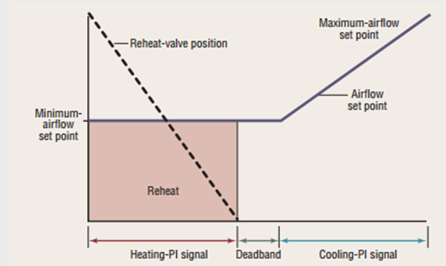
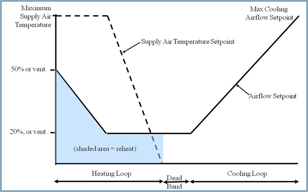
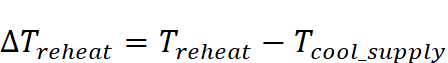
This is an alternate method to enter the terminal heat capacity, which can be calculated as follows:
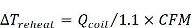
Where:

Heat rise across the terminal unit heating coil F)

Heating air temperature at design (F)

Supply air temperature at the heating coil (F)

Heating coil load (Btu/h)

Airflow (ft3/min)


Units

Degrees Fahrenheit (°F)

Input Restrictions

As designed but may need to be increased if zone unmet load hours are greater than 150

Standard Design

Method not used for standard design. The temperature difference shall be no more than 40°F. See heat capacity.

Standard Design:

Existing Buildings


5.6.4    Baseboard Heat

Note that a furnace zone system can be specified as a variation of baseboard heating.


Baseboard Capacity

Applicability

All thermal zones

Definition

Total heating capacity of the baseboard unit(s)

Units

Btu/h

Input Restrictions

As designed

Standard Design

Not applicable

Standard Design:

Existing Buildings


Baseboard Heat Control

Applicability

All thermal zones

Definition

Defines the control scheme of base board heating as controlled by a space thermostat

Units

List (see above)

Input Restrictions

Controlled by space thermostat is the only type allowed if baseboard heating is used.

Standard Design

Not applicable

Standard Design:

Existing Buildings


Baseboard Heat Source

Applicability

All thermal zones with furnaces or baseboard heating at the zone

Definition

Heating source

Units

List

     Electric heat

     Gas furnace

     Hot water

Input Restrictions


Standard Design

Not applicable

Standard Design:

Existing Buildings


5.6.5    Zone Level Air Flow

5.6.5.1  VAV Air Flow

This group of building descriptors applies to proposed design systems that vary the volume of air at the zone level. The building descriptors are applicable for standard design systems 5 and 6.


Design Airflow

Applicability

Systems that vary the volume of air at the zone level

Definition

The air delivery rate at design conditions

Units

Cfm

Input Restrictions

As designed

If the unmet load hours in the proposed design are greater than 150, the user may have to modify the design airflow value manually.

Standard Design

For systems 5 and 6, the software shall automatically size the system airflow to meet both:

a) the standard design peak cooling load based on a supply-air-to-room-air temperature difference of 20°F for exterior zones or 15°F for interior zones, the required ventilation air from Table 120.1-A of the standards, or makeup air, whichever is greater; and

b) the standard design peak heating load based on 50 percent zone flow and 95°F supply air temperature.

An exterior zone is defined as a type of thermal zone that has any exterior walls, and that has a non-zero amount of vertical fenestration (windows). Any zone that does not meet the definition of an exterior zone is an interior zone.

For kitchen MAU systems, the design airflow is the greater of the airflow required to meet the design cooling loads and the total exhaust cfm.

Standard Design:

Existing Buildings


Terminal Minimum Stop

Applicability

Systems that vary the volume of air at the zone level

Definition

The minimum airflow that will be delivered by a terminal unit before reheating occurs

Units

Unitless fraction of airflow (cfm) or specific airflow (cfm/ft²)

Input Restrictions

Input must be greater than or equal to the outside air ventilation rate

Standard Design

For systems 5 and 6, set the minimum airflow to be the greater of 20 percent of the peak supply air volume to the zone or the minimum outside air ventilation rate.

For laboratories, the minimum airflow fraction shall be fixed at a value equivalent to 6 ACH.

Standard Design:

Existing Buildings


Terminal Heating Control Type

Applicability

VAV boxes with reheat

/Definition

The control strategy for the heating mode.

Single Maximum:

In the single maximum control mode, the airflow is set to a minimum constant value in both the deadband and heating mode. This airflow can vary but is typically 30 to 50 percent of maximum. This control mode typically has a higher minimum airflow than the minimum used in the dual maximum below, resulting in more frequent reheat.

Figure 9: Single Maximum VAV Box Control

Source: Taylor Engineering

Dual Maximum:

Raises the supply air temperature (SAT) as the first stage of heating, and increases the airflow to the zone as the second stage of heating.

1.   The first stage of heating consists of modulating the zone supply air temperature setpoint up to a maximum setpoint no larger than 95°F while the airflow is maintained at the dead band flow rate.

2.   The second stage of heating consists of modulating the airflow rate from the dead band flow rate up to the heating maximum flow rate (50 percent of design flow rate).


Figure 10: Dual Maximum Control Sequence


Units

List:

     Single maximum

     Dual maximum

Input Restrictions

Fixed at single maximum if control system type is not direct digital control (DDC) control to the zone level

Standard Design

Dual maximum

Standard Design:

Existing Buildings


5.6.5.2  Fan Powered Boxes

Fan Powered Box Type

Applicability

Thermal zones that have fan powered boxes

Definition

Defines the type of fan-powered induction box

Units

List :

     series

     parallel

Input Restrictions

As designed

Standard Design

Not applicable

Standard Design:

Existing Buildings


Fan Power

Applicability

Thermal zones that have fan powered boxes

Definition

Rated power input of the fan in a fan-powered box

Units

W or W/cfm

Input Restrictions

As designed

Standard Design

Not applicable

Standard Design:

Existing Buildings


Fan Powered Box Induced Air Zone

Applicability

Thermal zones that have fan powered boxes

Definition

Zone from which a series or parallel fan-powered box draws its air

Units

List (of zones)

Input Restrictions

As designed

Standard Design

Not applicable

Standard Design:

Existing Buildings


Parallel PIU Induction Ratio

Applicability

Thermal zones that have fan-powered boxes

Definition

Ratio of induction-side airflow of a fan-powered box at design heating conditions to the primary airflow

Units

Ratio

Input Restrictions

As designed

Standard Design

Not applicable

Standard Design:

Existing Buildings


Parallel Fan Box Thermostat Setpoint

Applicability

Thermal zones that have fan powered boxes

Definition

Temperature difference above the heating setpoint at which the parallel fan is turned on

Units

Degrees Fahrenheit (°F)

Input Restrictions

2°F above the heating setpoint schedule

Standard Design

Not applicable

Standard Design:

Existing Buildings


5.6.5.3  Zone Exhaust

This group of building descriptors describes the rate of exhaust and the schedule or control for this exhaust. An exhaust system can serve one thermal zone or multiple thermal zones. Energy is summed for the exhaust system level, not the thermal zone level.

This section also contains unique inputs for kitchen exhaust systems that must meet requirements of section 140.9 of the standards.


Kitchen Exhaust Hood Length

Applicability

Exhaust fans in spaces of type kitchen, commercial food preparation

Definition

The exhaust hood length

Units

ft 

Input Restrictions

As designed

Standard Design

Same as the proposed design

Standard Design:

Existing Buildings


Kitchen Exhaust Hood Style

Applicability

Exhaust fans in spaces of type kitchen, commercial food preparation

Definition

The hood style as defined in Table 140.9-A of the standards

Units

List: 

     Wall-mounted canopy

     Single island

     Double island

     Eyebrow

     Backshelf/passover

Input Restrictions

As designed

Standard Design

Same as the proposed design

Standard Design:

Existing Buildings


Kitchen Exhaust Hood Cooking Duty

Applicability

Exhaust fans in spaces of type kitchen, commercial food preparation

Definition

The hood cooking duty as defined in Table140.9-A of the standards

Units

List: 

     Light-duty

     Medium-duty

     Heavy-duty

     Extra heavy-duty

Input Restrictions

As designed

Standard Design

Same as the proposed design

Standard Design:

Existing Buildings


Exhaust Fan Name

Applicability

All thermal zones

Definition

A reference to an exhaust fan system that serves the thermal zone

Units

Text or other unique reference to an exhaust fan system defined in the secondary systems section

Input Restrictions

As designed

Standard Design

Same as the proposed design

Standard Design:

Existing Buildings


Laboratory Exhaust Rate Type

Applicability

All zones comprised of laboratory, scientific or laboratory, equipment room space

Definition

The type of load that dictates lab exhaust rate requirements

Units

List:

     Hood-dominated

     Load-dominated

Input Restrictions

As designed

Standard Design

Same as the proposed design

Standard Design:

Existing Buildings


Exhaust Air Flow Rate

Applicability

All thermal zones

Definition

Rate of exhaust from a thermal zone

Units

cfm

Input Restrictions

As designed for non-process zones

As designed for kitchen exhaust systems

For laboratory zones, the exhaust air flow rate is defaulted to:

     15 ACH for hood dominated spaces, or

     6 ACH for load dominated spaces

The design exhaust air flow rate may be specified by the user, but a warning shall be posted if less than 6 ACH.

Standard Design

Same as the proposed design but not above the maximum standard design ventilation rates listed in Appendix 5.4A for spaces that do not include covered processes. Exception for buildings with over 5,000 cfm of kitchen exhaust; the baseline is a function of the kitchen exhaust hood length, kitchen exhaust hood style, and kitchen exhaust hood cooking duty, and is determined by Title 24 standards, Table 140.9-A -A.

For lab exhaust systems, the standard design is the same as the proposed.

Standard Design:

Existing Buildings


Exhaust Minimum Air Flow Rate

Applicability

All laboratory zones

Definition

Rate of exhaust from a zone

Units

cfm

Input Restrictions

As designed for non-process zones

For laboratory zones, the exhaust air flow rate is the maximum of the hood scheduled exhaust air flow rate and the minimum ventilation rate. A warning is posted if the design exhaust rate is 2 ACH or less.

Standard Design

For laboratory systems with constant flow exhaust fan control, the exhaust minimum air flow rate is 6 ACH. For laboratory systems with variable flow or variable speed drive exhaust fan control, the exhaust minimum air flow rate is 4 ACH.

Standard Design:

Existing Buildings


Exhaust Fan Schedule

Applicability

All thermal zones

Definition

Schedule indicating the pattern of use for exhaust air from the thermal zone

Units

Data structure: schedule, fraction

Input Restrictions

As designed for non-covered process spaces

Exhaust schedules for kitchen exhaust hoods in the building with total flow greater than or less than 5,000 cfm are prescribed and specified in Appendix 5.4B.

For laboratory spaces, if the exhaust is constant flow, the schedule shall be fixed at 0.90 for all hours of the year (24/7).

For laboratory spaces, if the exhaust is variable flow, all the schedule shall be prescribed at the values in Appendix 5.4B.

Standard Design

Same as the proposed design for non-covered process spaces

Exhaust schedules for kitchen exhaust hoods for flow less than 5,000 cfm and for flow greater than 5,000 cfm are prescribed and specified in Appendix 5.4B.

For laboratory spaces, if the proposed design exhaust air flow rate is greater than or equal to 10 ACH, the schedule shall be prescribed at 0.90 for all hours of the year (24/7).

For laboratory spaces, if the proposed design exhaust air flow rate is 10 ACH or less, the exhaust fan schedule shall be prescribed at the values defined in Appendix 5.4B for variable flow.

Standard Design:

Existing Buildings


5.6.5.4  Outdoor Air Ventilation

Ventilation Source

Applicability

All thermal zones

Definition

The source of ventilation for an HVAC system. The choices are:

     Natural (by operable openings)

     Mixed-mode (primary ventilation by HVAC fan, supplemented by natural ventilation when operable windows are open)

     Forced (by fan)

Units

List natural or forced

Input Restrictions

For residential units and hotel/motel guest rooms, as designed.

For all other occupancies, forced or mixed mode.

Standard Design

For residential units, the same modeling method as forced ventilation. Ventilation shall be provided by exhaust fans in each zone.

For all other occupancies, set to forced ventilation if the window type is fixed for all windows in the zone. If operable windows are specified, set to mixed mode.

Standard Design:

Existing Buildings


Ventilation Standard Source

Applicability

Thermal zones with special ventilation requirements, such as a process space, which have no defined requirements in Title 24

Definition

Minimum ventilation rates for:

     Title 24 (default)

     Other

Units

List: See above

Input Restrictions

None

User should be prepared to show justification for not using Title 24 ventilation source.

Standard Design

Same as proposed

Standard Design:

Existing Buildings


Design Ventilation Rate

Applicability

All thermal zones

Definition

The quantity of ventilation air that is provided to the space for the specified thermal zone at maximum occupancy.

This is adjusted by the occupancy fraction to determine the design ventilation rate for the space.

Units

cfm

Input Restrictions

To accommodate transfer air requirements for makeup air for exhaust from other zones, the design ventilation rate may be up to 120 percent of the proposed design exhaust rate for all spaces and thermal zones on a building story without penalty.

The minimum required ventilation rate for each space shall be the larger of 15 cfm times the design occupancy from Appendix 5.4A or the conditioned floor area times the applicable ventilation rate from Appendix 5.4A.

If the ventilation source is natural for residential dwelling spaces, then the proposed design design ventilation rate for compliance model purposes shall be zero.

Standard Design

If the total exhaust airflow requirement on the building floor does not exceed the total ventilation requirement, then the standard design outside air ventilation rate shall be the same as the proposed. If the proposed ventilation rate exceeds the default minimum, the standard design ventilation rate for each space shall be the proposed rate uniformly reduced such that the total ventilation air delivered to the building story is equal to the total minimum ventilation air rate:

Design Ventilation Ratestd = Design Ventilation Rateprop x ( BFVentstd / BFVentprop )

Where:

BFVentmin is the building floor design minimum required ventilation flow, as specified by the standards, and

BFVentprop is the building floor design ventilation flow for the proposed design.

If the total exhaust airflow requirement on the building floor exceeds the minimum required ventilation flow requirements:

The standard design outside air ventilation rate shall be the same as the proposed up to 120 percent of the design exhaust air flow. If the proposed ventilation rate exceeds 120 percent of the design exhaust flow, the standard design ventilation rate for each space shall be the proposed rate uniformly reduced such that the total ventilation air delivered to the building story is equal to 120 percent of the design exhaust flow rate:

Design Ventilation Ratestd = Design Ventilation Rateprop x ( BFExhprop x 1.2/BFVentprop )

Where:

BFExhprop is the building floor design exhaust flow, and

BFVentprop is the building floor design ventilation flow for the proposed design

If the ventilation source is “natural” for residential dwelling spaces, then the standard design (baseline) design ventilation rate for compliance model purposes shall be zero.

Standard Design:

Existing Buildings


Occupancy Fraction

Applicability

All thermal zones

Definition

The space design requirements for ventilation at design occupancy that are compliant with space egress requirements and design ventilation requirements.

The occupancy fraction also affects hot water use requirements for the space.

Units

Unitless fraction

Input Restrictions

Default of 0.5 as designed with a minimum value of 0.5 and a maximum value of 5

Standard Design

0.5

Standard Design:

Existing Buildings


Building Floor Ventilation Requirement

Applicability

Internal variable, calculated for each building story (floor)

Definition

The total outside air ventilation airflow requirement for all spaces on a building story or floor.

This is calculated by summing the ventilation levels for each space, and comparing it to the minimum required ventilation rate and the design exhaust air flow requirements.

Units

cfm (ft3/min)

Input Restrictions

Not a user input; derived by summing the ventilation and exhaust air flows from all spaces on the building floor

Standard Design

This is calculated by the following procedure:

1.   Calculate the proposed ventilation for the building story as the sum of design ventilation flow for each space included on a building story, including all spaces except space designated as lab space.

2.   Calculate the proposed exhaust for the building story as the sum of design exhaust flow for each space on the building story, including all spaces except spaces designated as lab space.

3.   Calculate the code minimum ventilation requirement as the sum of all minimum required ventilation airflows, as defined by Appendix 5.4A, for all spaces in the building story.

4.   If the proposed exhaust is greater than the code minimum ventilation rate, then:

a.   Total standard design building story ventilation requirement shall be:

Standard ventilation = Min (proposed ventilation, proposed exhaust  x 1.2)

Otherwise:

Standard ventilation = Min (code minimum ventilation, proposed ventilation)

Standard Design:

Existing Buildings


Minimum Ventilation Rate

Applicability

All thermal zones, excluding unconditioned spaces

Definition

The minimum quantity of ventilation air that must be provided to the space when it is occupied

Units

cfm (ft3/min)

Input Restrictions

As designed but not lower than code minimum (default value)

The default value shall be the larger of 15 cfm times the design occupancy times the occupancy fraction or the conditioned floor area times the applicable ventilation rate from Appendix 5.4A.

For spaces where demand control ventilation is installed, the minimum ventilation rate is specified by the greater of the rate in Table 120.1-A or 15 cfm times the scheduled occupancy for that hour.

For residential spaces where the proposed design ventilation source is natural ventilation, the minimum ventilation rate shall be zero.

Standard Design

For spaces where demand control ventilation is required, the minimum ventilation rate is specified by the greater of the rate in Appendix 5.4A or 15 cfm times the scheduled occupancy for that hour.

For systems serving laboratories, the airflow minimum for each lab space shall be 6 ACH for constant flow systems, or 4 ACH for variable flow systems.

For residential spaces where the proposed design ventilation source is natural ventilation, the standard design minimum ventilation rate shall be zero.

Standard Design:

Existing Buildings


Ventilation Control Method

Applicability

All thermal zones

Definition

The method used to determine outside air ventilation needed for each hour in the simulation.

This information is reported to the system serving the zone. The method of controlling outside air at the system level in response to this information is discussed under secondary systems. Options at the zone level are:

     Occupant sensors: When the space is occupied according to the prescribed occupancy schedule, the outside air requirement is equal to the design ventilation rate. Otherwise, the outside air requirement is either 25 percent of the minimum ventilation rate or scheduled off (0).

     CO2 sensors in the space: The outside air is varied to maintain a maximum CO2 concentration in the space. This shall be approximated by multiplying the ventilation rate per occupant times the number of occupants for that hour. (When turnstile counts are used to automatically adjust ventilation levels based on occupancy, this method may also be used.)

     Fixed ventilation rate: Outside air is delivered to the zone at a constant rate and is equal to the design ventilation rate (see above).

Units

List (see above)

Input Restrictions

As designed

If the space (other than a classroom space, which is exempted) includes a design occupant density greater than or equal to 25 persons per 1,000 ft2, and the system includes an airside economizer, the input is restricted to CO2 sensors in the space (a mandatory requirement).

Note: a classroom space greater than 750 ft2must have an occupancy sensor for ventilation control and setback to meet the mandatory Title 24 Standards requirements of 120.2(e)3. This requirement should be indicated on the appropriate compliance form submittal.

Standard Design

For the federal tax credit Title 24 compliance, if the default occupancy from Appendix 5.4B is greater than or equal to 25 persons per 1,000 ft² and the system includes and airside economizer and the space is not a classroom space, set control method to CO2 sensors in the space. Otherwise, set to fixed ventilation rate.

Standard Design:

Existing Buildings