|
|
| ||||||||||
|
Truss Spacing |
R-value of Attic Insulation |
|
Rated R-value of Continuous Insulation1 | ||||||||
|
|
None |
R-2 |
R-4 |
R-6 |
R-7 |
R-8 |
R-10 |
R-14 | |||
|
|
A |
B |
C |
D |
E |
F |
G |
H | |||
|
16 in. OC |
None |
1 |
0.300 |
0.187 |
0.136 |
0.107 |
0.097 |
0.088 |
0.075 |
0.058 | |
|
R-11 |
2 |
0.079 |
0.068 |
0.060 |
0.053 |
0.051 |
0.048 |
0.044 |
0.037 | ||
|
R-13 |
3 |
0.071 |
0.062 |
0.055 |
0.050 |
0.047 |
0.045 |
0.041 |
0.036 | ||
|
R-19 |
4 |
0.049 |
0.045 |
0.041 |
0.038 |
0.037 |
0.035 |
0.033 |
0.029 | ||
|
R-21 |
5 |
0.042 |
0.039 |
0.036 |
0.034 |
0.032 |
0.031 |
0.030 |
0.026 | ||
|
R-22 |
6 |
0.043 |
0.039 |
0.037 |
0.034 |
0.033 |
0.032 |
0.030 |
0.027 | ||
|
R-25 |
7 |
0.038 |
0.035 |
0.033 |
0.031 |
0.030 |
0.029 |
0.028 |
0.025 | ||
|
R-30 |
8 |
0.032 |
0.030 |
0.028 |
0.027 |
0.026 |
0.025 |
0.024 |
0.022 | ||
|
R-38 |
9 |
0.026 |
0.024 |
0.023 |
0.022 |
0.022 |
0.021 |
0.020 |
0.019 | ||
|
R-44 |
10 |
0.021 |
0.020 |
0.019 |
0.019 |
0.018 |
0.018 |
0.017 |
0.016 | ||
|
R-49 |
11 |
0.020 |
0.019 |
0.019 |
0.018 |
0.018 |
0.017 |
0.017 |
0.016 | ||
|
R-60 |
12 |
0.017 |
0.016 |
0.016 |
0.015 |
0.015 |
0.015 |
0.014 |
0.013 | ||
|
24 in. OC |
None |
13 |
0.305 |
0.189 |
0.137 |
0.108 |
0.097 |
0.089 |
0.075 |
0.058 | |
|
R-11 |
14 |
0.076 |
0.066 |
0.058 |
0.052 |
0.050 |
0.047 |
0.043 |
0.037 | ||
|
R-13 |
15 |
0.068 |
0.060 |
0.054 |
0.048 |
0.046 |
0.044 |
0.041 |
0.035 | ||
|
R-19 |
16 |
0.048 |
0.043 |
0.040 |
0.037 |
0.036 |
0.034 |
0.032 |
0.029 | ||
|
R-21 |
17 |
0.043 |
0.040 |
0.037 |
0.034 |
0.033 |
0.032 |
0.030 |
0.027 | ||
|
R-22 |
18 |
0.041 |
0.038 |
0.036 |
0.033 |
0.032 |
0.031 |
0.029 |
0.026 | ||
|
R-25 |
19 |
0.037 |
0.034 |
0.032 |
0.030 |
0.029 |
0.028 |
0.027 |
0.024 | ||
|
R-30 |
20 |
0.031 |
0.029 |
0.028 |
0.026 |
0.025 |
0.025 |
0.024 |
0.022 | ||
|
R-38 |
21 |
0.025 |
0.024 |
0.023 |
0.022 |
0.021 |
0.021 |
0.020 |
0.018 | ||
|
R-44 |
22 |
0.021 |
0.020 |
0.019 |
0.019 |
0.018 |
0.018 |
0.017 |
0.016 | ||
|
R-49 |
23 |
0.019 |
0.019 |
0.018 |
0.017 |
0.017 |
0.017 |
0.016 |
0.015 | ||
|
R-60 |
24 |
0.016 |
0.016 |
0.015 |
0.015 |
0.014 |
0.014 |
0.014 |
0.013 | ||
|
Notes: 1. Continuous insulation shall be located at the ceiling, below the bottom chord of the truss and be uninterrupted by framing. 2. In climate zones 1 and 16 the insulating R-value of continuous insulation materials installed above the roofs waterproof membrane shall be multiplied by 0.8 before choosing the table column for determining assembly U-factor. | |||||||||||
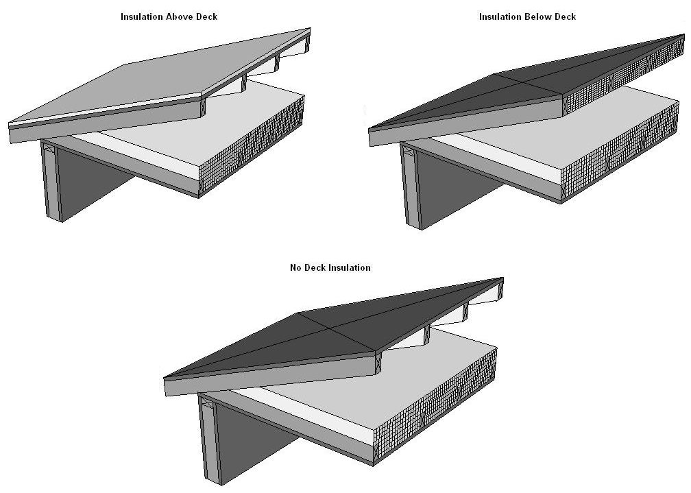
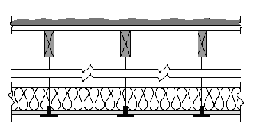
This table contains thermal performance data (U-factors) for wood framed attics where the ceiling provides the air barrier and the attic is ventilated. Wood trusses are the most common construction for low-rise residential buildings and for Type V nonresidential buildings. While the sketch shows a truss system with a flat ceiling, the data in this table may be used for scissor trusses and other non-flat trusses. If the bottom chord is not flat, then the slope should not exceed 4:12 for nonadhesive binder blown insulation. This table may also be used with composite trusses that have a wood top and bottom chord and metal struts connecting them.
For the majority of cases, values will be selected from column A of this table. Column A shall be used for the common situation where either batt or blown insulation is placed directly over the ceiling (and tapered at the edges). Builders or designers may increase thermal performance by adding a continuous insulation layer at the ceiling. The continuous insulation is typically a rigid polystyrene or polyisocyanurate foam insulation. Continuous insulation does not include the blown or batt insulation that is over the bottom chord of the truss (this is already accounted for in the U-factors published in Column A).
When this table is used manually, the R-value of continuous insulation shall be equal to or greater than the R-value published in the continuous insulation columns. For instance if the insulation is R-3, the R-2 column shall be used. No interpolation is permitted when data from the table is selected manually. CEC approved compliance software, including those used for prescriptive compliance, may accurately account for any amount of continuous insulation or for unusual construction assemblies using Equation 4-1 and Equation 4-2.
This table shall not be used for cases where insulation is located at the roof of the attic. There are several situations in which this may be done. For example, in a sealed attic, foamed plastic may be sprayed onto the top chord of the trusses and onto the bottom of the upper structural deck (roof). The foam expands and cures with the intent of providing an airtight barrier and continuous insulation. Another case is where a plastic membrane or netting is installed above the ceiling (hanging below the roof deck) either in a ventilated or sealed (not ventilated) attic, and then either batt or blown insulation is installed over the netting. Since there are a number of issues related to these insulation techniques, special CEC approval is required.
Assumptions: This data is calculated using the parallel path method documented in the 2009 ASHRAE Handbook of Fundamentals. These calculations assume an exterior air film of R-0.17, asphalt shingles of R-0.44 (AR02), building paper of R-0.06 (BP01), ½ inch of wood based sheathing (Custom), an attic air space (greater than 3.5 inch) with a R-0.80, the insulation / framing layer, continuous insulation (if any) 1/2 inch gypsum board (GP01) of R-0.45, and an interior air film (heat flow up) of R-0.61. Wood 2x4 framing is assumed at the ceiling level. R-13 of attic insulation is assumed between the framing members; above that level, attic insulation is uninterrupted by framing. The framing percentage is assumed to be 10 percent for 16 inch on center and 7 percent for 24 inch on center. 7.25 percent of the attic insulation above the framing members is assumed to be at half depth, due to decreased depth of insulation at the eaves.
|
Rafter |
R-value of |
Nominal Framing |
|
Rated R-value of Continuous Insulation5 | |||||||
|
|
None |
R-2 |
R-4 |
R-6 |
R-7 |
R-8 |
R-10 |
R-14 | |||
|
|
A |
B |
C |
D |
E |
F |
G |
H | |||
|
16 in. OC |
None |
Any |
1 |
0.297 |
0.186 |
0.136 |
0.107 |
0.096 |
0.088 |
0.075 |
0.058 |
|
|
R-112 |
2x4 |
2 |
0.084 |
0.072 |
0.063 |
0.056 |
0.053 |
0.050 |
0.046 |
0.039 |
|
|
R-132 |
2x4 |
3 |
0.075 |
0.065 |
0.058 |
0.052 |
0.049 |
0.047 |
0.043 |
0.037 |
|
|
R-152 |
2x4 |
4 |
0.068 |
0.060 |
0.053 |
0.048 |
0.046 |
0.044 |
0.040 |
0.035 |
|
|
R-192 |
2x4 |
5 |
0.075 |
0.065 |
0.058 |
0.052 |
0.049 |
0.047 |
0.043 |
0.037 |
|
|
R-192,3 |
2x4 |
6 |
0.062 |
0.055 |
0.050 |
0.045 |
0.043 |
0.041 |
0.038 |
0.033 |
|
|
R-11 |
2x6 |
7 |
0.076 |
0.066 |
0.058 |
0.052 |
0.050 |
0.047 |
0.043 |
0.037 |
|
|
R-13 |
2x6 |
8 |
0.069 |
0.061 |
0.054 |
0.049 |
0.047 |
0.044 |
0.041 |
0.035 |
|
|
R-15 |
2x6 |
9 |
0.062 |
0.055 |
0.050 |
0.045 |
0.043 |
0.041 |
0.038 |
0.033 |
|
|
R-192 |
2x6 |
10 |
0.056 |
0.050 |
0.046 |
0.042 |
0.040 |
0.039 |
0.036 |
0.031 |
|
|
R-212 |
2x6 |
11 |
0.052 |
0.047 |
0.043 |
0.040 |
0.038 |
0.037 |
0.034 |
0.030 |
|
|
R-192 |
2x8 |
12 |
0.051 |
0.046 |
0.042 |
0.039 |
0.038 |
0.036 |
0.034 |
0.030 |
|
|
R-21 |
2x8 |
13 |
0.048 |
0.044 |
0.040 |
0.037 |
0.036 |
0.035 |
0.032 |
0.029 |
|
|
R-22 |
2x10 |
14 |
0.044 |
0.040 |
0.037 |
0.035 |
0.034 |
0.033 |
0.031 |
0.027 |
|
|
R-25 |
2x10 |
15 |
0.041 |
0.038 |
0.035 |
0.033 |
0.032 |
0.031 |
0.029 |
0.026 |
|
|
R-304 |
2x10 |
16 |
0.036 |
0.034 |
0.031 |
0.030 |
0.029 |
0.028 |
0.026 |
0.024 |
|
|
R-30 |
2x12 |
17 |
0.035 |
0.033 |
0.031 |
0.029 |
0.028 |
0.027 |
0.026 |
0.023 |
|
|
R-384 |
2x12 |
18 |
0.029 |
0.027 |
0.026 |
0.025 |
0.024 |
0.024 |
0.022 |
0.021 |
|
|
R-384 |
2x14 |
19 |
0.028 |
0.027 |
0.025 |
0.024 |
0.023 |
0.023 |
0.022 |
0.020 |
|
24 in. OC |
None |
Any |
25 |
0.237 |
0.161 |
0.122 |
0.098 |
0.089 |
0.082 |
0.070 |
0.055 |
|
|
R-112 |
2x4 |
26 |
0.081 |
0.070 |
0.061 |
0.055 |
0.052 |
0.049 |
0.045 |
0.038 |
|
|
R-132 |
2x4 |
27 |
0.072 |
0.063 |
0.056 |
0.050 |
0.048 |
0.046 |
0.042 |
0.036 |
|
|
R-152 |
2x4 |
28 |
0.065 |
0.058 |
0.052 |
0.047 |
0.045 |
0.043 |
0.039 |
0.034 |
|
|
R-192 |
2x4 |
29 |
0.072 |
0.063 |
0.056 |
0.050 |
0.048 |
0.046 |
0.042 |
0.036 |
|
|
R-192,3 |
2x4 |
30 |
0.059 |
0.053 |
0.048 |
0.044 |
0.042 |
0.040 |
0.037 |
0.032 |
|
|
R-11 |
2x6 |
31 |
0.075 |
0.065 |
0.058 |
0.052 |
0.049 |
0.047 |
0.043 |
0.037 |
|
|
R-13 |
2x6 |
32 |
0.067 |
0.059 |
0.053 |
0.048 |
0.046 |
0.044 |
0.040 |
0.035 |
|
|
R-152 |
2x6 |
33 |
0.060 |
0.054 |
0.048 |
0.044 |
0.042 |
0.041 |
0.038 |
0.033 |
|
|
R-192 |
2x6 |
34 |
0.054 |
0.049 |
0.044 |
0.041 |
0.039 |
0.038 |
0.035 |
0.031 |
|
|
R-212 |
2x6 |
35 |
0.049 |
0.045 |
0.041 |
0.038 |
0.036 |
0.035 |
0.033 |
0.029 |
|
|
R-192 |
2x8 |
36 |
0.049 |
0.045 |
0.041 |
0.038 |
0.036 |
0.035 |
0.033 |
0.029 |
|
|
R-21 |
2x8 |
37 |
0.046 |
0.042 |
0.039 |
0.036 |
0.035 |
0.034 |
0.032 |
0.028 |
|
|
R-22 |
2x10 |
38 |
0.043 |
0.040 |
0.037 |
0.034 |
0.033 |
0.032 |
0.030 |
0.027 |
|
|
R-25 |
2x10 |
39 |
0.039 |
0.036 |
0.034 |
0.032 |
0.031 |
0.030 |
0.028 |
0.025 |
|
|
R-304 |
2x10 |
40 |
0.034 |
0.032 |
0.030 |
0.028 |
0.027 |
0.027 |
0.025 |
0.023 |
|
|
R-30 |
2x12 |
41 |
0.033 |
0.031 |
0.029 |
0.028 |
0.027 |
0.026 |
0.025 |
0.023 |
|
|
R-38 4 |
2x12 |
42 |
0.028 |
0.027 |
0.025 |
0.024 |
0.023 |
0.023 |
0.022 |
0.020 |
|
|
R-384 |
2x14 |
43 |
0.027 |
0.026 |
0.024 |
0.023 |
0.023 |
0.022 |
0.021 |
0.020 |
|
Notes: 1. Rigid foam board used for cavity insulation must fill the entire cavity between the rafters and be sealed properly to prevent air gaps, and must be secured properly to prevent any future discrepancies in the construction assembly. 2. This assembly is only allowed where ventilation is provided between the bottom of the roof deck and the top of the insulation meeting CBC requirements or with enforcement agency official’s approval of rafter attic assemblies with no ventilation air spaces. 3. This assembly requires insulation with an R-value per inch 5.6 or larger (k-factor 1.8 or less). This is board type insulation, mostly Isocyanurate. Medium density spray polyurethane foam may also be used to meet this requirement if the quality installation procedures and documentation in Reference Joint Appendix JA7 are followed, Documentation from Directory of Certified insulation materials must be provided to show compliance with this assembly. 4. Higher density fiberglass batt is needed to achieve the indicated U-factor. R-30 must be achieved with less than 8.25 inch full thickness. R-38 must be achieved with less than 10.25 inch thickness (R-30c, R-38c). 5. Continuous insulation shall be located at the ceiling or at the roof and be uninterrupted by framing. In climate zones 1 and 16 the insulating R-value of continuous insulation materials installed above the roofs waterproof membrane shall be multiplied by 0.8 before choosing the table column for determining assembly U-factor. | |||||||||||
This table contains thermal performance data (U-factors) for wood framed rafter roofs. This is a common construction in low-rise residential buildings and in Type V nonresidential buildings. The rafters may be either flat or in a sloped application. Insulation is typically installed between the rafters. With this construction, the insulation is in contact with the ceiling and there is typically a one-inch air gap above the insulation so that moisture can be vented. Whether there is an air space above the insulation depends on local climate conditions and may not be required in some building permit jurisdictions. Filling the entire cavity of framed rafter assemblies with loose-fill mineral fiber and wool, cellulose, or ocSPF requires prior approval by the local building official.
For the majority of cases, U-factors will be selected from Column A of this table; this case covers insulation placed only in the cavity. When continuous insulation is installed either at the ceiling or at the roof, then U-factors from other columns may be selected. The continuous insulation is typically a rigid polystyrene or polyisocyanurate foam insulation, but can also include mineral wool or other suitable materials.

When this table is used manually, the R-value of continuous insulation shall be equal to or greater than the R-value published in the continuous insulation columns. For instance if the continuous insulation is R-3, the R-2 column shall be used. No interpolation is permitted when data from the table is used manually. CEC approved software, however, may determine the U-factor for any amount of continuous insulation and/or for layers using Equation 4-1 and Equation 4-2.
Assumptions: These data are calculated using the parallel path method documented in the 2009 ASHRAE Handbook of Fundamentals. These calculations assume an exterior air film of R-0.17, asphalt shingles of R-0.44 (AR02), building paper of R-0.06 (BP01), ½ inch of wood based sheathing (Custom), continuous insulation (optional), the insulation / framing layer with an air space of R-0.76 or R-0.80 (except for loose-fill mineral fiber and wool, cellulose, ccSPF, and ocSPF), 1/2 inch gypsum of R-0.45 (GP01), and an interior air film (heat flow up diagonally) of R-0.62. The continuous insulation may also be located at the ceiling, between the drywall and the framing. The framing percentage is assumed to be 10 percent for 16 inch OC and 7 percent for 24 inch. OC. The thickness of framing members is assumed to be the actual size of 3.50, 5.50, 7.25, 9.25, and 11.25 inches for 2x4, 2x6, 2x8, 2x10, and 2x12 nominal sizes. High-density batt insulation is assumed to be 8.5 inch thick for R-30 and 10.5 inch thick for R-38. The R-value of sprayed foam and cellulose insulation is assumed to be R-3.6 per inch.
|
Wood Framing Connection Type (spline) |
Insulation Core R-value1 |
Typical Panel Thickness |
|
Rated R-value of Continuous Insulation 4,5 |
|
| |||
|
|
None |
R-2 |
R-4 |
R-5 |
R-7 |
R-8 | |||
|
|
A |
B |
C |
D |
E |
F | |||
|
OSB |
R-22 |
6.5 in |
1 |
0.041 |
0.038 |
0.035 |
0.034 |
0.032 |
0.031 |
|
Single 2x |
R-22 |
6.5 in |
2 |
0.044 |
0.040 |
0.037 |
0.036 |
0.033 |
0.032 |
|
Double 2x |
R-22 |
6.5 in |
3 |
0.046 |
0.042 |
0.038 |
0.037 |
0.034 |
0.033 |
|
I-joist |
R-22 |
6.5 in |
4 |
0.043 |
0.039 |
0.036 |
0.035 |
0.033 |
0.032 |
|
OSB |
R-28 |
8.25 in |
5 |
0.033 |
0.031 |
0.029 |
0.028 |
0.027 |
0.026 |
|
Single 2x |
R-28 |
8.25 in |
6 |
0.034 |
0.032 |
0.030 |
0.029 |
0.027 |
0.027 |
|
Double 2x |
R-28 |
8.25 in |
7 |
0.037 |
0.034 |
0.031 |
0.030 |
0.028 |
0.028 |
|
I-joist |
R-28 |
8.25 in |
8 |
0.033 |
0.310 |
0.029 |
0.028 |
0.027 |
0.026 |
|
OSB |
R-332 |
6.5 in |
9 |
0.030 |
0.027 |
0.026 |
0.025 |
0.024 |
0.023 |
|
Single 2x |
R-332 |
6.5 in |
10 |
0.031 |
0.029 |
0.027 |
0.026 |
0.025 |
0.024 |
|
Double 2x |
R-332 |
6.5 in |
11 |
0.034 |
0.031 |
0.029 |
0.028 |
0.026 |
0.025 |
|
I-joist |
R-332 |
6.5 in |
12 |
0.031 |
0.028 |
0.027 |
0.026 |
0.025 |
0.024 |
|
OSB |
R-36 |
10.25 in |
13 |
0.026 |
0.025 |
0.024 |
0.023 |
0.022 |
0.022 |
|
Single 2x |
R-36 |
10.25 in |
14 |
0.028 |
0.026 |
0.025 |
0.024 |
0.023 |
0.022 |
|
Double 2x |
R-36 |
10.25 in |
15 |
0.029 |
0.028 |
0.026 |
0.025 |
0.024 |
0.023 |
|
I-joist |
R-36 |
10.25 in |
16 |
0.027 |
0.025 |
0.024 |
0.023 |
0.022 |
0.022 |
|
OSB |
R-44 |
12.25 in |
17 |
0.021 |
0.020 |
0.019 |
0.019 |
0.018 |
0.018 |
|
Single 2x |
R-44 |
12.25 in |
18 |
0.023 |
0.022 |
0.021 |
0.021 |
0.020 |
0.019 |
|
Double 2x |
R-44 |
12.25 in |
19 |
0.025 |
0.023 |
0.022 |
0.022 |
0.021 |
0.020 |
|
I-joist |
R-44 |
12.25 in |
20 |
0.022 |
0.021 |
0.020 |
0.020 |
0.019 |
0.019 |
|
OSB |
R-553 |
10.25 in |
21 |
0.017 |
0.016 |
0.016 |
0.016 |
0.016 |
0.016 |
|
Single 2x |
R-553 |
10.25 in |
22 |
0.019 |
0.018 |
0.018 |
0.018 |
0.017 |
0.016 |
|
Double 2x |
R-553 |
10.25 in |
23 |
0.021 |
0.020 |
0.019 |
0.019 |
0.018 |
0.017 |
|
I-joist |
R-553 |
10.25 in |
24 |
0.018 |
0.017 |
0.017 |
0.017 |
0.016 |
0.016 |
|
Steel Framing |
R-14 |
48 in |
25 |
0.075 |
0.065 |
0.058 |
0.055 |
0.049 |
0.047 |
|
|
R-22 |
48 in |
26 |
0.057 |
0.051 |
0.046 |
0.044 |
0.041 |
0.039 |
|
|
R-28 |
48 in |
27 |
0.047 |
0.043 |
0.040 |
0.039 |
0.035 |
0.034 |
|
|
R-36 |
48 in |
28 |
0.043 |
0.040 |
0.037 |
0.036 |
0.033 |
0.032 |
|
NOTES: 1. The insulation R-value must be at least R-21.7 in order to use this table. This table assumes moulded expanded polystyrene (EPS) unless noted otherwise. Although other insulation types are used by some SIP manufacturers, such as polyurethane and extruded expanded insulation (XPS), EPS is the most common insulation used in SIP construction. 2. R-33.2 is achievable using polyurethane insulation in 6.5" panels. 3. R-55.3 is achievable using polyurethane insulation in 10.25" panels. 4. Continuous insulation shall be at least R-2 and may be installed on either the inside or the exterior of the roof/ceiling. 5. In climate zones 1 and 16 the insulating R-value of continuous insulation materials installed above the roof waterproof membrane shall be multiplied times 0.8 before choosing the table column for determining assembly U-factor. | |||||||||
Structural insulated panels (SIPs) consist of a rigid insulation core, securely bonded between two structural facings, to form a structural sandwich panel. SIPs are considered a non-framed assembly usually with little or no structural framing that penetrates the insulation layer, resulting in less thermal bridging across the insulation when compared to a conventional framed assembly.
This table gives U-factors for structurally insulated panels used in ceiling and roof constructions. Data is provided for three variations of this system. The system labeled “Wood Framing” uses wood spacers to separate the plywood or OSB boards and provide a means to connect the panels with mechanical fasteners. The system labeled “Steel Framing” uses steel framing members and mechanical fasteners at the joints. The system labeled “OSB Spline” uses splines to connect the panels so that framing members do not penetrate the insulation.
|
|
|
|
| |
Data from Column A will be used in most cases, since it is quite unusual to add continuous insulation to a panel that is basically all insulation anyway. If insulation is added, however, then the U-factor is selected from one of the other columns. If the tables are used manually, then the installed insulation shall have a thermal resistance at least as great as the column selected. When the table is used with CEC approved compliance software, then the R-value of any amount of continuous insulation may be accounted for along with the thermal resistance of special construction layers may be accounted for using Equation 4-1 and Equation 4-2.
Assumptions: The wood framing and OSB spline data are calculated using the parallel path method documented in the 2009 ASHRAE Handbook of Fundamentals. Assemblies with metal framing are calculated using the ASHRAE Zone Calculation Method which is also documented in the 2005 ASHRAE Handbook of Fundamentals. These calculations assume an exterior air film of R-0.17, asphalt shingles of R-0.44 (AR02), building paper of R-0.06 (BP01), 7/16 inch of OSB of R-0.69, the rigid insulation of R-3.85 per inch, another layer of 7/16 inch of OSB, ½ inch gypsum board of R-0.45 (GP01), an R-value of 0.99 per inch is assumed for the wood frame and an interior air film (heat flow up diagonally) of R-0.62. If an additional layer of insulation is used, this may be installed on either the interior or exterior of the SIPS panel assembly.
|
|
|
|
|
| |||||||
|
Spacing |
Nominal Framing Size |
Cavity Insulation R-Value: |
|
Rated R-value of Continuous Insulation1 | |||||||
|
|
R-0 |
R-2 |
R-4 |
R-6 |
R-7 |
R-8 |
R-10 |
R-14 | |||
|
|
A |
B |
C |
D |
E |
F |
G |
H | |||
|
16 in. OC |
Any |
None |
1 |
0.328 |
0.198 |
0.142 |
0.111 |
0.100 |
0.091 |
0.077 |
0.059 |
|
|
2 x 4 |
R-11 |
2 |
0.126 |
0.101 |
0.084 |
0.072 |
0.067 |
0.063 |
0.056 |
0.046 |
|
|
(3.65 in.) |
R-13 |
3 |
0.121 |
0.097 |
0.082 |
0.070 |
0.066 |
0.061 |
0.055 |
0.045 |
|
|
|
R-19 |
4 |
0.071 |
0.062 |
0.055 |
0.050 |
0.047 |
0.045 |
0.042 |
0.036 |
|
|
|
R-21 |
5 |
0.063 |
0.056 |
0.050 |
0046 |
0.044 |
0.042 |
0.039 |
0.033 |
|
|
|
R-22 |
6 |
0.059 |
0.053 |
0.048 |
0.044 |
0.042 |
0.040 |
0.037 |
0.032 |
|
|
|
R-25 |
7 |
0.051 |
0.046 |
0.042 |
0.039 |
0.038 |
0.036 |
0.034 |
0.030 |
|
|
|
R-30 |
8 |
0.041 |
0.038 |
0.035 |
0.033 |
0.032 |
0.031 |
0.029 |
0.026 |
|
|
|
R-38 |
9 |
0.031 |
0.029 |
0.028 |
0.026 |
0.025 |
0.025 |
0.024 |
0.022 |
|
|
|
R-44 |
10 |
0.027 |
0.026 |
0.024 |
0.023 |
0.023 |
0.022 |
0.021 |
0.020 |
|
|
|
R-49 |
11 |
0.024 |
0.023 |
0.022 |
0.021 |
0.021 |
0.020 |
0.019 |
0.018 |
|
|
|
R-60 |
12 |
0.019 |
0.018 |
0.018 |
0.017 |
0.017 |
0.016 |
0.016 |
0.015 |
|
24 in. OC |
Any |
None |
13 |
0.324 |
0.197 |
0.141 |
0.110 |
0.099 |
0.090 |
0.076 |
0.059 |
|
|
2 x 4 |
R-11 |
14 |
0.109 |
0.089 |
0.076 |
0.066 |
0.062 |
0.058 |
0.052 |
0.043 |
|
|
(3.65 in.) |
R-13 |
15 |
0.103 |
0.085 |
0.073 |
0.064 |
0.060 |
0.056 |
0.051 |
0.042 |
|
|
|
R-19 |
16 |
0.065 |
0.058 |
0.052 |
0.047 |
0.045 |
0.043 |
0.039 |
0.034 |
|
|
|
R-21 |
17 |
0.058 |
0.052 |
0.047 |
0.043 |
0.041 |
0.040 |
0.037 |
0.032 |
|
|
|
R-22 |
18 |
0.055 |
0.050 |
0.045 |
0.041 |
0.040 |
0.038 |
0.035 |
0.031 |
|
|
|
R-25 |
19 |
0.047 |
0.043 |
0.040 |
0.037 |
0.035 |
0.034 |
0.032 |
0.028 |
|
|
|
R-30 |
20 |
0.039 |
0.036 |
0.034 |
0.032 |
0.031 |
0.030 |
0.028 |
0.025 |
|
|
|
R-38 |
21 |
0.030 |
0.028 |
0.027 |
0.025 |
0.025 |
0.024 |
0.023 |
0.021 |
|
|
|
R-44 |
22 |
0.026 |
0.025 |
0.024 |
0.022 |
0.022 |
0.022 |
0.021 |
0.019 |
|
|
|
R-49 |
23 |
0.023 |
0.022 |
0.021 |
0.020 |
0.020 |
0.019 |
0.019 |
0.017 |
|
|
|
R-60 |
24 |
0.019 |
0.018 |
0.018 |
0.017 |
0.017 |
0.016 |
0.016 |
0.015 |
|
Notes: 1 Continuous insulation shall be located at the ceiling or at the roof and be uninterrupted by framing. 2. In climate zones 1 and 16 the insulating R-value of continuous insulation materials installed above the roofs waterproof membrane shall be multiplied by 0.8 before choosing the table column for determining assembly U-factor. | |||||||||||
This table contains U-factors for metal-framed attic roofs, where the ceiling is the air barrier and the attic is ventilated. This construction assembly is similar to those that are covered by Table 4.2.1, except that metal framing members are substituted for the wood-framing members. The top chord of the truss is typically sloped, while the bottom chord is typically flat. Data from this table may be used for cases where the bottom chord of the truss is sloped. If the bottom chord slopes more than 4:12, nonadhesive binder blown insulation must not be used.
For the majority of cases, values will be selected from column A of this table. Column A applies for the common situation where either batt or blown insulation is placed directly over the ceiling. Builders or designers may increase thermal performance by adding a continuous insulation layer at the ceiling. The continuous insulation is typically a rigid polystyrene or polyisocyurnate foam insulation. Continuous insulation does not include the blown or batt insulation that is over the bottom chord of the truss (this is already accounted for in the first column data).
When this table is used manually, the R-value of continuous insulation shall be equal to or greater than the R-value published in the continuous insulation columns. No interpolation is permitted when data from the table is used manually. CEC approved software, however, may determine the U-factor for any amount of continuous insulation and for unusual construction layers using Equation 4-1 and Equation 4-2.

Assumptions: These data are calculated using the zone method calculation documented in the 2009 ASHRAE Handbook of Fundamentals. These calculations assume an exterior air film of R-0.17, asphalt shingles of R-0.44 (AR02), building paper of R-0.06 (BP01), ½ inch of wood based sheathing (Custom), the attic air space (greater than 3.5 inch) of R-0.80, the insulation / framing layer, continuous insulation (if any) 1/2 inch gypsum of R-0.45 (GP01), and an interior air film (heat flow up) of R-0.61. The framing percentage is assumed to be 10 percent for 16 inch on center and 7 percent for 24 inch on center 7.25 percent of the attic insulation above the framing members is assumed to be at half depth, due to decreased depth of insulation at the eaves. Steel framing has 1.5 inch flange and is 0.0747 inch thick steel with no knockouts. U-factors calculated using EZ Frame 2.0.
|
|
| |||||||||||
|
Spacing |
R-Value of Insulation Between Framing |
Nominal Framing Size |
|
Rated R-value of Continuous Insulation | ||||||||
|
|
R-0 |
R-2 |
R-4 |
R-6 |
R-7 |
R-8 |
R-10 |
R-14 | ||||
|
|
A |
B |
C |
D |
E |
F |
G |
H | ||||
|
16 in. OC |
None |
Any |
1 |
0.325 |
0.197 |
0.141 |
0.110 |
0.099 |
0.090 |
0.076 |
0.059 | |
|
|
R-112 |
2x4 |
2 |
0.129 |
0.103 |
0.085 |
0.073 |
0.068 |
0.063 |
0.056 |
0.046 | |
|
|
R-132 |
2x4 |
3 |
0.121 |
0.097 |
0.082 |
0.070 |
0.066 |
0.061 |
0.055 |
0.045 | |
|
|
R-152 |
2x4 |
4 |
0.115 |
0.093 |
0.079 |
0.068 |
0.064 |
0.060 |
0.053 |
0.044 | |
|
|
R-192,3 |
2x4 |
5 |
0.121 |
0.097 |
0.082 |
0.070 |
0.066 |
0.061 |
0.055 |
0.045 | |
|
|
R-11 |
2x6 |
6 |
0.123 |
0.099 |
0.082 |
0.071 |
0.066 |
0.062 |
0.055 |
0.045 | |
|
|
R-13 |
2x6 |
7 |
0.115 |
0.093 |
0.079 |
0.068 |
0.064 |
0.060 |
0.053 |
0.044 | |
|
|
R-152 |
2x6 |
8 |
0.101 |
0.084 |
0.072 |
0.063 |
0.059 |
0.056 |
0.050 |
0.042 | |
|
|
R-192 |
2x6 |
9 |
0.100 |
0.083 |
0.071 |
0.063 |
0.059 |
0.056 |
0.050 |
0.042 | |
|
|
R-192 |
2x8 |
10 |
0.096 |
0.081 |
0.069 |
0.061 |
0.057 |
0.054 |
0.049 |
0.041 | |
|
|
R-21 |
2x8 |
11 |
0.093 |
0.078 |
0.068 |
0.060 |
0.056 |
0.053 |
0.048 |
0.040 | |
|
|
R-25 |
2x10 |
12 |
0.084 |
0.072 |
0.063 |
0.056 |
0.053 |
0.050 |
0.046 |
0.039 | |
|
|
R-304 |
2x10 |
13 |
0.079 |
0.068 |
0.060 |
0.054 |
0.051 |
0.048 |
0.044 |
0.038 | |
|
|
R-30 |
2x12 |
14 |
0.076 |
0.066 |
0.058 |
0.052 |
0.050 |
0.047 |
0.043 |
0.037 | |
|
|
R-38 4 |
2x12 |
15 |
0.071 |
0.062 |
0.055 |
0.050 |
0.047 |
0.045 |
0.042 |
0.036 | |
|
|
R-38 4 |
2x14 |
16 |
0.068 |
0.060 |
0.053 |
0.048 |
0.046 |
0.044 |
0.040 |
0.035 | |
|
24 in. OC |
None |
Any |
22 |
0.322 |
0.196 |
0.141 |
0.110 |
0.099 |
0.090 |
0.076 |
0.058 | |
|
|
R-112 |
2x4 |
23 |
0.111 |
0.091 |
0.077 |
0.067 |
0.062 |
0.059 |
0.053 |
0.043 | |
|
|
R-132 |
2x4 |
24 |
0.102 |
0.085 |
0.072 |
0.063 |
0.060 |
0.056 |
0.050 |
0.042 | |
|
|
R-152 |
2x4 |
25 |
0.096 |
0.081 |
0.069 |
0.061 |
0.057 |
0.054 |
0.049 |
0.041 | |
|
|
R-192,3 |
2x4 |
26 |
0.102 |
0.085 |
0.072 |
0.063 |
0.060 |
0.056 |
0.050 |
0.042 | |
|
|
R-11 |
2x6 |
27 |
0.107 |
0.088 |
0.075 |
0.065 |
0.061 |
0.058 |
0.052 |
0.043 | |
|
|
R-13 |
2x6 |
28 |
0.099 |
0.083 |
0.071 |
0.062 |
0.058 |
0.055 |
0.050 |
0.041 | |
|
|
R-152 |
2x6 |
29 |
0.086 |
0.073 |
0.064 |
0.057 |
0.054 |
0.051 |
0.046 |
0.039 | |
|
|
R-192 |
2x6 |
30 |
0.083 |
0.071 |
0.062 |
0.055 |
0.052 |
0.050 |
0.045 |
0.038 | |
|
|
R-192 |
2x8 |
31 |
0.080 |
0.0690 |
0.061 |
0.054 |
0.051 |
0.049 |
0.044 |
0.038 | |
|
|
R-21 |
2x8 |
32 |
0.076 |
0.066 |
0.058 |
0.052 |
0.050 |
0.047 |
0.043 |
0.037 | |
|
|
R-25 |
2x10 |
33 |
0.068 |
0.060 |
0.053 |
0.048 |
0.046 |
0.044 |
0.040 |
0.035 | |
|
|
R-304 |
2x10 |
34 |
0.063 |
0.056 |
0.050 |
0.046 |
0.044 |
0.042 |
0.039 |
0.033 | |
|
|
R-30 |
2x12 |
35 |
0.061 |
0.054 |
0.049 |
0.045 |
0.043 |
0.041 |
0.038 |
0.033 | |
|
|
R-384 |
2x12 |
36 |
0.055 |
0.050 |
0.045 |
0.041 |
0.040 |
0.038 |
0.035 |
0.031 | |
|
|
R-384 |
2x14 |
37 |
0.053 |
0.048 |
0.044 |
0.040 |
0.039 |
0.037 |
0.035 |
0.030 | |
|
Notes: 1. Rigid foam board used for cavity insulation must fill the entire cavity between the rafters and be sealed properly to prevent air gaps, and must be secured properly to prevent any future discrepancies in the construction assembly. 2. This assembly is only allowed where ventilation is provided between the bottom of the roof deck and the top of the insulation meeting, CBC requirements or enforcement agency officials approval of rafter attic assemblies with no ventilation air spaces. 3. This assembly requires insulation with an R-value per inch 5.6 or larger (k-factor 1.8 or less). This is board type insulation, mostly Isocyanurate. Medium density spray polyurethane foam may also be used to meet this requirement if the quality installation procedures and documentation in Joint Appendix 7 are followed. Documentation from Directory of Certified insulation materials must be provided to show compliance with this assembly. 4. Higher density fiberglass batt is needed to achieve the indicated U-factor. R-30 must be achieved with less than 8.25 inch full thickness. R-38 must be achieved with less than 10.25 inch thickness (R-30c, R-38c).
| ||||||||||||
This table contains pre-calculated U-factors for metal-framed rafter roofs where the ceiling is the air barrier. This construction assembly is similar to that covered by Table 4.2.2 except that metal framing members are substituted for the wood-framing members. The rafters may be either flat or in a sloped application. Insulation is typically installed between the rafters. With this construction, the insulation is in contact with the ceiling and there is typically a one-inch air gap above the insulation so that moisture can be vented. Whether there is an air space above the insulation depends on local climate conditions and may not be required in some building permit jurisdictions.
U-factors are selected from Column A of this table when there is no continuous insulation. When continuous insulation is installed either at the ceiling or at the roof, then U-factors from other columns may be selected. The continuous insulation is typically a rigid polystyrene or polyisocyanurate foam insulation, but can also include mineral wool or other suitable materials.

When this table is used manually, the R-value of continuous insulation shall be equal to or greater than the R-value published in the continuous insulation columns. For instance if the insulation is R-3, the R-2 column shall be used. No interpolation is permitted when data from the table is used manually. Commission approved software, however, may determine the U-factor for any amount of continuous insulation and/or for unusual construction layers using Equation 4-1 and Equation 4-2.
Assumptions: These data are calculated using the zone calculation method documented in the 2009 ASHRAE Handbook of Fundamentals. These calculations assume an exterior air film of R-0.17, asphalt shingles of R-0.44 (AR02), building paper of R-0.06 (BP01), ½ inch of wood based sheathing (Custom), the insulation / framing layer, ½ inch gypsum of R-0.45 (GP01), and an interior air film (heat flow up diagonally) of R-0.62 The continuous insulation may either be located at the ceiling or over the structural deck. The thickness of framing members is assumed to be 3.50, 5.50, 7.25, 9.25, and 11.25 inch for 2x4, 2x6, 2x8, 2x10, and 2x12 nominal sizes. High-density batt insulation is assumed to be 8.5 in. thick for R-30 and 10.5 in thick for R-38. Framing spacing is 10 percent for 16 inches on center and 7 percent for 24 inches on center. Steel framing has 1.5 inch flange and is 0.075 inch thick steel with no knockouts. U-factors calculated using EZ Frame 2.0.
|
|
|
|
| |||||||||
|
Fireproofing |
Concrete Topping Over Metal Deck |
|
R-value of Continuous Insulation | |||||||||
|
|
None |
R-4 |
R-6 |
R-8 |
R-10 |
R-12 |
R-15 |
R-20 |
R-25 |
R-30 | ||
|
|
A |
B |
C |
D |
E |
F |
G |
H |
I |
J | ||
|
Yes |
None |
1 |
0.348 |
0.145 |
0.113 |
0.092 |
0.078 |
0.067 |
0.056 |
0.044 |
0.036 |
0.030 |
|
|
2 in. |
2 |
0.324 |
0.141 |
0.110 |
0.090 |
0.076 |
0.066 |
0.055 |
0.043 |
0.036 |
0.030 |
|
|
4 in. |
3 |
0.302 |
0.137 |
0.107 |
0.088 |
0.075 |
0.065 |
0.055 |
0.043 |
0.035 |
0.030 |
|
|
6 in. |
4 |
0.283 |
0.133 |
0.105 |
0.087 |
0.074 |
0.064 |
0.054 |
0.042 |
0.035 |
0.030 |
|
No |
None |
5 |
0.503 |
0.167 |
0.125 |
0.100 |
0.083 |
0.071 |
0.059 |
0.045 |
0.037 |
0.031 |
|
|
2 in. |
6 |
0.452 |
0.161 |
0.122 |
0.098 |
0.082 |
0.070 |
0.058 |
0.045 |
0.037 |
0.031 |
|
|
4 in. |
7 |
0.412 |
0.156 |
0.119 |
0.096 |
0.080 |
0.069 |
0.057 |
0.045 |
0.036 |
0.031 |
|
|
6 in. |
8 |
0.377 |
0.150 |
0.116 |
0.094 |
0.079 |
0.068 |
0.057 |
0.044 |
0.036 |
0.031 |
|
1. In climate zones 1 and 16 the insulating R-value of continuous insulation materials installed above the roof waterproof membrane shall be multiplied by 0.8 before choosing the table column for determining assembly U-factor. | ||||||||||||
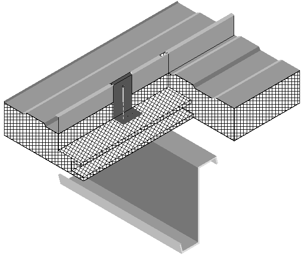
The constructions in this table are typical of Type I and Type II steel framed or concrete nonresidential buildings. The construction consists of a metal deck with or without a concrete topping. It may also be used for a metal deck or even wood deck ceiling as long as the insulation is continuous. Fireproofing may be sprayed onto the underside of the metal deck; it also covers steel structural members. Insulation is typically installed above the structural deck and below the waterproof membrane. This table may also be used for reinforced concrete roofs that do not have a metal deck. In this case, the fireproofing will typically not be installed and choices from the table should be made accordingly.
When this table is used manually, the R-value of continuous insulation shall be equal to or greater than the R-value published in the continuous insulation columns. No interpolation is permitted when data from the table is used manually. Commission approved compliance software, however, may determine the U-factor for any amount of continuous insulation and for unusual construction layers using Equation 4-1 and Equation 4-2. If the data is adjusted using Equation 4-2, the user shall take credit for a ceiling and the air space above the ceiling only if the ceiling serves as an air barrier. Suspended or T-bar ceilings do not serve as air barriers.

Assumptions: These calculations are made using the parallel path method documented in the 2009 ASHRAE Handbook of Fundamentals. The assembly is assumed to consist of an exterior air film of R-0.17, a single ply roofing membrane (R-0.15), protective board (R-1.06), continuous insulation (if any), concrete topping with a density of 120 lb/ft and an R-value of 0.11 per inch (if any), metal span deck (negligible), and fireproofing (R-0.88). While a suspended ceiling typically exists below the structure, this is not considered part of the construction assembly therefore the same U-values are used for assemblies with or without suspended ceilings. The fireproofing is assumed to be equivalent to 60 lb/ft³ concrete with a resistance of 0.44 per inch.
|
Insulation System |
R-Value of Insulation |
Overall U-Factor for Entire Base Roof Assembly |
|
Rated R-value of Continuous Insulation | ||||||||
|
|
|
R-6 |
R-9 |
R-13 |
R-15 |
R-19 |
R-22 |
R-25 |
R-32 |
R-38 | ||
|
|
A |
B |
C |
D |
E |
F |
G |
H |
I | |||
|
Screw Down Roofs (no Thermal Blocks) |
R-10 |
0.184 |
1 |
0.087 |
0.069 |
0.054 |
0.049 |
0.041 |
0.036 |
0.033 |
0.027 |
0.023 |
|
R-11 |
0.182 |
2 |
0.087 |
0.069 |
0.054 |
0.049 |
0.041 |
0.036 |
0.033 |
0.027 |
0.023 | |
|
R-13 |
0.174 |
3 |
0.085 |
0.068 |
0.053 |
0.048 |
0.040 |
0.036 |
0.033 |
0.026 |
0.023 | |
|
R-16 |
0.157 |
4 |
0.081 |
0.065 |
0.052 |
0.047 |
0.039 |
0.035 |
0.032 |
0.026 |
0.023 | |
|
R-19 |
0.151 |
5 |
0.079 |
0.064 |
0.051 |
0.046 |
0.039 |
0.035 |
0.032 |
0.026 |
0.022 | |
|
Standing Seam Roof with Single Layer of Insulation Draped over Purlins and Compressed. Thermal blocks at supports.2 |
None |
1.280 |
6 |
0.147 |
0.102 |
0.073 |
0.063 |
0.051 |
0.044 |
0.039 |
0.031 |
0.026 |
|
R-10 |
0.115 |
7 |
0.068 |
0.057 |
0.046 |
0.042 |
0.036 |
0.033 |
0.030 |
0.025 |
0.021 | |
|
R-11 |
0.107 |
8 |
0.065 |
0.055 |
0.045 |
0.041 |
0.035 |
0.032 |
0.029 |
0.024 |
0.021 | |
|
R-13 |
0.101 |
9 |
0.063 |
0.053 |
0.044 |
0.040 |
0.035 |
0.031 |
0.029 |
0.024 |
0.021 | |
|
R-16 |
0.096 |
10 |
0.061 |
0.052 |
0.043 |
0.039 |
0.034 |
0.031 |
0.028 |
0.024 |
0.021 | |
|
R-19 |
0.082 |
11 |
0.055 |
0.047 |
0.040 |
0.037 |
0.032 |
0.029 |
0.027 |
0.023 |
0.020 | |
|
Standing Seam Roof with Double Layer of Insulation.3Thermal blocks at supports.2 |
R-10 + R-10 |
0.088 |
12 |
0.058 |
0.049 |
0.041 |
0.038 |
0.033 |
0.030 |
0.028 |
0.023 |
0.020 |
|
R-10 + R-11 |
0.086 |
13 |
0.057 |
0.048 |
0.041 |
0.038 |
0.033 |
0.030 |
0.027 |
0.023 |
0.020 | |
|
R-11 + R-11 |
0.085 |
14 |
0.056 |
0.048 |
0.040 |
0.037 |
0.033 |
0.030 |
0.027 |
0.023 |
0.020 | |
|
R-10 + R-13 |
0.084 |
15 |
0.056 |
0.048 |
0.040 |
0.037 |
0.032 |
0.029 |
0.027 |
0.023 |
0.020 | |
|
R-11 + R-13 |
0.082 |
16 |
0.055 |
0.047 |
0.040 |
0.037 |
0.032 |
0.029 |
0.027 |
0.023 |
0.020 | |
|
R-13 + R-13 |
0.075 |
17 |
0.052 |
0.045 |
0.038 |
0.035 |
0.031 |
0.028 |
0.026 |
0.022 |
0.019 | |
|
R-10 + R-19 |
0.074 |
18 |
0.051 |
0.044 |
0.038 |
0.035 |
0.031 |
0.028 |
0.026 |
0.022 |
0.019 | |
|
R-11 + R-19 |
0.072 |
19 |
0.050 |
0.044 |
0.037 |
0.035 |
0.030 |
0.028 |
0.026 |
0.022 |
0.019 | |
|
R-13 + R-19 |
0.068 |
20 |
0.048 |
0.042 |
0.036 |
0.034 |
0.030 |
0.027 |
0.025 |
0.021 |
0.019 | |
|
R-16 + R-19 |
0.065 |
21 |
0.047 |
0.041 |
0.035 |
0.033 |
0.029 |
0.027 |
0.025 |
0.021 |
0.019 | |
|
R-19 + R-19 |
0.060 |
22 |
0.044 |
0.039 |
0.034 |
0.032 |
0.028 |
0.026 |
0.024 |
0.021 |
0.018 | |
|
Filled Cavity with Thermal Blocks 3,4,5 |
R10 + R-19 |
0.041 |
23 |
0.033 |
0.030 |
0.027 |
0.025 |
0.023 |
0.022 |
0.020 |
0.018 |
0.016 |
|
|
Notes: 1. A roof must have metal purlins no closer than 4 ft on center to use this table. If the roof deck is attached to the purlins more frequently than 12 in oc, 0.008 must be added to the U-factors in this table. 2. Thermal blocks are an R-3 of rigid insulation, which extends 1.5" beyond the width of the purlin on each side. 3. Multiple R-values are listed in order from outside to inside. First layer is parallel to the purlins, and supported by a system; second layer is laid on top of the purlins. 4. Thermal blocks are an R-5 of rigid insulation, which extends 1.5" beyond the width of the purlin on each side. 5. In
climate zones 1 and 16 the insulating R-value of continuous insulation
materials installed above the roof waterproof membrane shall be multiplied
times 0.8 before choosing the table column for determining assembly
U-factor. | |||||||||||
The U-factors in this table are intended for use with metal building roofs. This type of construction is typical for manufacturing and warehouse facilities, but is used for other building types as well. The typical method of insulating this type of building is to drape vinyl backed fiberglass insulation over the metal purlins before the metal deck is attached with metal screws. With this method, the insulation is compressed at the supports, reducing its effectiveness. The first part of the table contains values for this insulation technique. The second section of the table has data for the case when a thermal block is used at the support. The insulation is still compressed, but the thermal block, which generally consists of an 8 inch wide strip of foam insulation, improves the thermal performance. The third section of the table deals with systems that involve two layers of insulation.
|
Screw-Down,
|
Single
Layer, |
|
|
|
|
Double
Layer, |
Filled
Cavity, |
|
|
|
For the majority of cases, values will be selected from column A of this table. Builders or designers may increase thermal performance by adding a continuous insulation layer between the metal decking and the structural supports. The continuous insulation is typically a rigid polystyrene or polyisocyanurate foam insulation.
When this table is used manually, the R-value of continuous insulation shall be equal to or greater than the R-value published in the continuous insulation columns. No interpolation is permitted when data from the table is used manually. Commission approved compliance software, however, may determine the U-factor for any amount of continuous insulation using Equation 4-1.
Assumptions: Data in Column A of this table is taken from the ASHRAE/IESNA Standard 90.1-2004, Appendix A. The data is also published in the NAIMA Compliance for Metal Buildings, 1997.
|
|
|
U-factor |
|
R-value of Insulation Over Suspended Ceiling |
|
A |
|
None |
1 |
0.304 |
|
7 |
2 |
0.152 |
|
11 |
3 |
0.132 |
|
13 |
4 |
0.126 |
|
19 |
5 |
0.113 |
|
21 |
6 |
0.110 |
|
22 |
7 |
0.109 |
|
30 |
8 |
0.102 |
|
38 |
9 |
0.098 |
|
49 |
10 |
0.094 |
|
60 |
11 |
0.092 |
This table includes U-factors for the case of insulation placed over suspended ceilings. This situation is only permitted for a combined floor area no greater than 2,000 square feet in an otherwise unconditioned building, and when the average height of the space between the ceiling and the roof over these spaces is greater than 12 feet. The suspended ceiling does not provide an effective air barrier and leakage is accounted for in the calculations.
Assumptions: These calculations assume an exterior air film of R-0.17, a built-up roof of R-0.33 (BR01), ¾ inch wood based sheathing (Custom), a twelve foot air space of R-0.80, the insulation (for the insulated portion), removable ceiling panels with a R-0.50 and an interior air film (heat flow up) of R-0.61. 75 percent of the ceiling is assumed covered by insulation and the remainder is not insulated. The uninsulated portion includes lighting fixtures and areas where the insulation is not continuous. A correction factor of 0.005 is added to the resulting U-factor to account for infiltration through the suspended ceiling and lighting fixtures.
|
|
|
U-factor (Btu/0F-ft2) |
|
Panel Thickness |
|
A |
|
2” |
1 |
0.079 |
|
2 ½” |
2 |
0.064 |
|
3” |
3 |
0.054 |
|
4” |
4 |
0.041 |
|
5” |
5 |
0.033 |
|
6” |
6 |
0.028 |
This table contains thermal performance data (U-factors) for foamed-in-place, insulated metal panels consisting of liquid polyurethane or polyisocyanurate injected between metal skins in individual molds or on fully automated production lines. Metal building construction is the most common application for this product where the metal panel is fastened to the frame of the structure. This table can only be used for insulated panels that are factory built. This table does not apply to panels that utilize polystyrene, or to field applied products such as spray applied insulations.
Assumptions: These data are calculated using the parallel path method documented in the 2009 ASHRAE Handbook of Fundamentals. These calculations assume an exterior air film of R-0.17, light gauge metal exterior of R-0.0747, continuous insulation R-5.9 per inch, light gauge metal interior of 0.0747 inch thickness and an interior air film (heat flow up) of R-0.61. The panels are assumed to be continuous with no framing penetration. The R-value of the light gauge metal is negligible.


