
|
Spacing |
Cavity Insulation |
Nominal Framing Size |
|
|
|
|
Rated R-value of Continuous Insulation 2 |
|
| ||||||
|
|
|
|
R-0 |
R-2 |
R-4 |
R-5 |
R-6 |
R-7 |
R-8 |
R-10 |
R-12 |
R-15 | |||
|
|
A |
B |
C |
D |
E |
F |
G |
H |
I |
J | |||||
|
16 in. OC |
None |
Any |
1 |
0.356 |
0.209 |
0.146 |
0.127 |
0.113 |
0.101 |
0.092 |
0.078 |
0.067 |
0.056 | ||
|
|
R-11 |
2x4 |
2 |
0.110 |
0.088 |
0.074 |
0.068 |
0.064 |
0.060 |
0.056 |
0.050 |
0.045 |
0.040 | ||
|
|
R-13 |
2x4 |
3 |
0.102 |
0.082 |
0.069 |
0.064 |
0.060 |
0.056 |
0.053 |
0.047 |
0.043 |
0.038 | ||
|
|
R-15 1 |
2x4 |
4 |
0.095 |
0.077 |
0.065 |
0.060 |
0.056 |
0.053 |
0.050 |
0.045 |
0.041 |
0.036 | ||
|
|
R-19 |
2x6 |
5 |
0.074 |
0.063 |
0.055 |
0.051 |
0.049 |
0.046 |
0.044 |
0.040 |
0.037 |
0.033 | ||
|
|
R-211 |
2x6 |
6 |
0.069 |
0.059 |
0.051 |
0.048 |
0.046 |
0.043 |
0.041 |
0.038 |
0.035 |
0.031 | ||
|
|
R-22 |
2x6 |
7 |
0.072 |
0.062 |
0.054 |
0.051 |
0.048 |
0.045 |
0.043 |
0.037 |
0.036 |
0.033 | ||
|
|
R-23 |
2x6 |
8 |
0.067 |
0.057 |
0.049 |
0.047 |
0.044 |
0.042 |
0.040 |
0.037 |
0.034 |
0.030 | ||
|
|
R-25 |
2x6 |
9 |
0.065 |
0.055 |
0.048 |
0.045 |
0.043 |
0.040 |
0.039 |
0.035 |
0.036 |
0.032 | ||
|
|
R-19 |
2x8 |
10 |
0.065 |
0.057 |
0.051 |
0.048 |
0.045 |
0.043 |
0.041 |
0.038 |
0.035 |
0.032 | ||
|
|
R-22 |
2x8 |
11 |
0.061 |
0.053 |
0.047 |
0.045 |
0.043 |
0.041 |
0.039 |
0.036 |
0.033 |
0.030 | ||
|
|
R-25 |
2x8 |
12 |
0.057 |
0.050 |
0.044 |
0.042 |
0.040 |
0.038 |
0.037 |
0.034 |
0.032 |
0.029 | ||
|
|
R-301 |
2x8 |
13 |
0.056 |
0.049 |
0.044 |
0.041 |
0.040 |
0.038 |
0.036 |
0.033 |
0.031 |
0.028 | ||
|
24 in. OC |
None |
Any |
14 |
0.362 |
0.211 |
0.148 |
0.128 |
0.114 |
0.102 |
0.092 |
0.078 |
0.067 |
0.056 | ||
|
|
R-11 |
2x4 |
15 |
0.106 |
0.086 |
0.072 |
0.067 |
0.062 |
0.059 |
0.055 |
0.050 |
0.045 |
0.039 | ||
|
|
R-13 |
2x4 |
16 |
0.098 |
0.079 |
0.067 |
0.062 |
0.058 |
0.055 |
0.052 |
0.047 |
0.043 |
0.038 | ||
|
|
R-15 |
2x4 |
17 |
0.091 |
0.074 |
0.063 |
0.059 |
0.055 |
0.052 |
0.049 |
0.044 |
0.040 |
0.036 | ||
|
|
R-19 |
2x6 |
18 |
0.071 |
0.061 |
0.053 |
0.050 |
0.048 |
0.045 |
0.043 |
0.040 |
0.036 |
0.033 | ||
|
|
R-211 |
2x6 |
19 |
0.066 |
0.057 |
0.050 |
0.047 |
0.045 |
0.042 |
0.040 |
0.037 |
0.034 |
0.031 | ||
|
|
R-22 |
2x6 |
20 |
0.069 |
0.060 |
0.052 |
0.049 |
0.047 |
0.044 |
0.042 |
0.036 |
0.036 |
0.033 | ||
|
|
R-23 |
2x6 |
21 |
0.064 |
0.054 |
0.048 |
0.045 |
0.043 |
0.041 |
0.039 |
0.036 |
0.033 |
0.030 | ||
|
|
R-25 |
2x6 |
22 |
0.061 |
0.052 |
0.046 |
0.043 |
0.041 |
0.039 |
0.037 |
0.034 |
0.035 |
0.031 | ||
|
|
R-19 |
2x8 |
23 |
0.063 |
0.055 |
0.049 |
0.047 |
0.045 |
0.043 |
0.041 |
0.037 |
0.035 |
0.031 | ||
|
|
R-22 |
2x8 |
24 |
0.058 |
0.051 |
0.046 |
0.044 |
0.042 |
0.040 |
0.038 |
0.035 |
0.033 |
0.030 | ||
|
|
R-25 |
2x8 |
25 |
0.055 |
0.048 |
0.043 |
0.041 |
0.039 |
0.037 |
0.036 |
0.033 |
0.031 |
0.028 | ||
|
|
R-301 |
2x8 |
26 |
0.054 |
0.047 |
0.042 |
0.040 |
0.038 |
0.037 |
0.035 |
0.033 |
0.030 |
0.028 | ||
|
Notes 1. Higher density fiberglass batt is required in these cases. 2. Continuous insulation may be installed on either the inside or the exterior of the wall, or both. | |||||||||||||||
This table contains U-factors for wood framed walls, which
are typical of low-rise residential buildings and Type V nonresidential
buildings. If continuous insulation is not used, then choices are made from
Column A. In this case, the insulation is installed in the cavity between the
framing members. When continuous insulation is used, this is typically installed on the
exterior side of the wall, but can also be used on the inside. The continuous
insulation is typically a rigid polystyrene or polyisocyanurate foam
insulation.
When this table is used manually, the R-value of continuous insulation shall be equal to or greater than the R-value published in the continuous insulation columns. No interpolation is permitted when data from the table is used manually. Commission approved compliance software, however, may determine the U-factor for any amount of continuous insulation or for unusual construction assemblies using Equation 4-1 and Equation 4-2.
(See addendum at the end of this Section on page 4-75 for table 4.3.1(a) entitled “Table 4.3.1(a) – U-factors of Wood Framed Walls with 5/8 gypsum1 (Only to be used when 5/8 inch gypsum is installed)”
Assumptions: Values in this table were calculated using the parallel heat flow calculation method, documented in the 2009 ASHRAE Handbook of Fundamentals. The construction assembly assumes an exterior air film of R-0.17, a 7/8 inch layer of stucco of R-0.18 (SC01), building paper of R-0.06 (BP01), continuous insulation (if any), the cavity insulation / framing layer, ½ inch gypsum board of R-0.45 (GP01), and an interior air film 0.68. The framing factor is assumed to be 25 percent for 16 inch stud spacing and 22 percent for 24 inch spacing. Actual cavity depth is 3.5 inch for 2x4, 5.5 inch for 2x6, 7.25 inch for 2x8, 9.25 inch for 2x10, and 11.25 inch for 2x12. High density R-30 insulation is assumed to be 8.5 inch thick batt and R-38 is assumed to be 10.5 inch thick. The thickness of the stucco is assumed to be reduced to 3/8 inch when continuous insulation is applied.
|
Wood Framing Connection Type (spline) |
Insulation Core R-value1 |
Typical Panel Thickness |
|
Rated R-value of Continuous Insulation 5 |
|
| |||
|
|
None |
R-2 |
R-4 |
R-5 |
R-6 |
R-8 | |||
|
|
A |
B |
C |
D |
E |
F | |||
|
OSB |
R-14 |
4.5 in |
1 |
0.061 |
0.055 |
0.049 |
0.047 |
0.045 |
0.041 |
|
Single 2x |
R-14 |
4.5 in |
2 |
0.071 |
0.061 |
0.054 |
0.051 |
0.048 |
0.044 |
|
Double 2x |
R-14 |
4.5 in |
3 |
0.077 |
0.065 |
0.057 |
0.054 |
0.050 |
0.046 |
|
I-joist |
R-14 |
4.5 in |
4 |
0.070 |
0.060 |
0.053 |
0.051 |
0.048 |
0.044 |
|
OSB |
R-182 |
4.5 in |
5 |
0.053 |
0.045 |
0.041 |
0.039 |
0.037 |
0.034 |
|
Single 2x |
R-182 |
4.5 in |
6 |
0.061 |
0.052 |
0.047 |
0.045 |
0.042 |
0.039 |
|
Double 2x |
R-182 |
4.5 in |
7 |
0.066 |
0.056 |
0.050 |
0.048 |
0.045 |
0.041 |
|
I-joist |
R-182 |
4.5 in |
8 |
0.059 |
0.051 |
0.046 |
0.044 |
0.042 |
0.038 |
|
OSB |
R-22 |
6.5 in |
9 |
0.041 |
0.038 |
0.036 |
0.035 |
0.033 |
0.031 |
|
Single 2x |
R-22 |
6.5 in |
10 |
0.050 |
0.044 |
0.040 |
0.039 |
0.037 |
0.034 |
|
Double 2x |
R-22 |
6.5 in |
11 |
0.054 |
0.048 |
0.043 |
0.041 |
0.039 |
0.036 |
|
I-joist |
R-22 |
6.5 in |
12 |
0.048 |
0.043 |
0.039 |
0.038 |
0.036 |
0.033 |
|
OSB |
R-28 |
8.25 in |
13 |
0.032 |
0.030 |
0.029 |
0.028 |
0.027 |
0.026 |
|
Single 2x |
R-28 |
8.25 in |
14 |
0.039 |
0.036 |
0.033 |
0.032 |
0.031 |
0.029 |
|
Double 2x |
R-28 |
8.25 in |
15 |
0.043 |
0.039 |
0.035 |
0.034 |
0.033 |
0.030 |
|
I-joist |
R-28 |
8.25 in |
16 |
0.037 |
0.034 |
0.032 |
0.031 |
0.030 |
0.028 |
|
OSB |
R-333 |
6.5 in |
17 |
0.032 |
0.029 |
0.027 |
0.026 |
0.025 |
0.023 |
|
Single 2x |
R-333 |
6.5 in |
18 |
0.038 |
0.034 |
0.031 |
0.030 |
0.029 |
0.027 |
|
Double 2x |
R-333 |
6.5 in |
19 |
0.043 |
0.038 |
0.034 |
0.033 |
0.031 |
0.029 |
|
I-joist |
R-333 |
6.5 in |
20 |
0.036 |
0.033 |
0.030 |
0.029 |
0.028 |
0.026 |
|
OSB |
R-36 |
10.25 in |
21 |
0.026 |
0.024 |
0.023 |
0.023 |
0.022 |
0.021 |
|
Single 2x |
R-36 |
10.25 in |
22 |
0.032 |
0.030 |
0.028 |
0.027 |
0.026 |
0.024 |
|
Double 2x |
R-36 |
10.25 in |
23 |
0.035 |
0.032 |
0.030 |
0.029 |
0.028 |
0.026 |
|
I-joist |
R-36 |
10.25 in |
24 |
0.030 |
0.028 |
0.026 |
0.026 |
0.025 |
0.023 |
|
OSB |
R-44 |
12.25 in |
25 |
0.022 |
0.021 |
0.020 |
0.020 |
0.019 |
0.018 |
|
Single 2x |
R-44 |
12.25 in |
26 |
0.027 |
0.025 |
0.024 |
0.023 |
0.022 |
0.021 |
|
Double 2x |
R-44 |
12.25 in |
27 |
0.028 |
0.027 |
0.025 |
0.025 |
0.024 |
0.023 |
|
I-joist |
R-44 |
12.25 in |
28 |
0.025 |
0.024 |
0.022 |
0.022 |
0.021 |
0.020 |
|
OSB |
R-554 |
10.25 in |
29 |
0.020 |
0.019 |
0.017 |
0.016 |
0.016 |
0.016 |
|
Single 2x |
R-554 |
10.25 in |
30 |
0.024 |
0.022 |
0.021 |
0.021 |
0.020 |
0.019 |
|
Double 2x |
R-554 |
10.25 in |
31 |
0.028 |
0.025 |
0.023 |
0.023 |
0.022 |
0.021 |
|
I-joist |
R-554 |
10.25 in |
32 |
0.022 |
0.021 |
0.019 |
0.019 |
0.018 |
0.018 |
|
Notes: 1. The insulation R-value must be at least R-14 in order to use this table. This table assumes moulded expanded polystyrene (EPS) unless noted otherwise. Although other insulation types are used by some SIP manufacturers, such as polyurethane and extruded expanded insulation (XPS), EPS is the most common insulation used in SIP construction. 2. R-18.1 is achievable using extruded expanded polystyrene (XPS) insulation in 4.5" thick panels. 3. R-33.2 is achievable using polyurethane insulation in 6.5" panels. 4. R-55.3 is achievable using polyurethane insulation in 10.25" panels. 5. Continuous insulation shall be at least R-2 and may be installed on either the inside or the exterior of the wall. | |||||||||
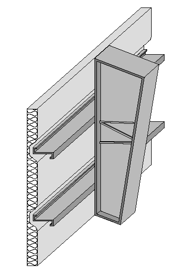
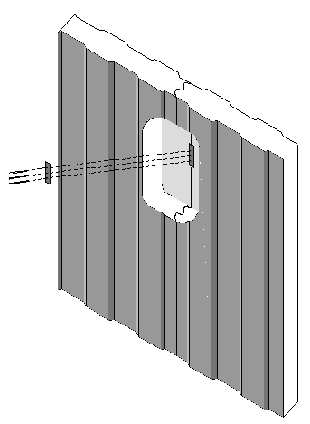
Structural insulated panels (SIPs) consist of a rigid insulation core, securely bonded between two structural facings, to form a structural sandwich panel. SIPs are considered a non-framed assembly usually with little or no structural framing that penetrates the insulation layer, resulting in less thermal bridging across the insulation when compared to a conventional framed assembly.
This table gives U-factors for structurally insulated panels used in wall construction. This is a construction system that consists of rigid foam insulation sandwiched between two layers of plywood or oriented strand board (OSB). Data is provided for four variations of connecting two panels together.
If continuous insulation is not used, then choices are made from Column A. When continuous insulation is also used, this is typically installed on the exterior side of the wall, but can also be used on the inside. The continuous insulation is typically a rigid polystyrene or polyisocyanurate foam insulation. Adding continuous insulation to a SIPS panel is highly unusual since the panel itself is mostly continuous insulation.
When this table is used manually, the R-value of continuous insulation shall be equal to or greater than the R-value published in the continuous insulation columns. No interpolation is permitted when data from the table is used manually. Commission approved software, however, may determine the U-factor for any amount of continuous insulation or for unusual construction assemblies using Equation 4-1 and Equation 4-2.
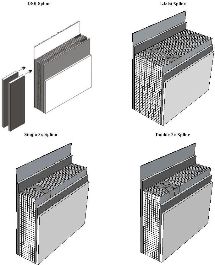
This figure shows just one way that panels are connected. Other options exist.
Assumptions: These data are calculated using the parallel path method documented in the 2009 ASHRAE Handbook of Fundamentals.
These calculations assume an exterior air film of R-0.17, a 7/8 inch layer of stucco of R-0.18, building paper of R-0.06 (BP01), 7/16 inch of OSB of R-0.44, insulation at carrying R-values (as specified), 7/16 inch of OSB of R-0.44, ½ inch gypsum board of R-0.45 (GP01), and in interior air film of R-0.68. A framing factor of 13 percent is assumed for wood spacers and 7 percent for the OSB spline system. Framing includes the sill plate, the header and framing around windows and doors.
|
Cavity Insulation R-Value: |
Nominal Framing Size |
|
|
|
Rated R-value of Continuous Insulation 2 |
|
|
|
|
|
| ||||||||
|
|
R-0 |
R-2 |
R-4 |
R-5 |
R-6 |
R-7 |
R-8 |
R-10 |
R-12 |
R-14 |
R-15 |
| |||||||
|
|
A |
B |
C |
D |
E |
F |
G |
H |
I |
J |
K |
| |||||||
|
16 in. OC |
None |
Any |
1 |
0.458 |
0.239 |
0.162 |
0.139 |
0.122 |
0.109 |
0.098 |
0.082 |
0.071 |
0.062 |
0.058 |
| ||||
|
|
R-5 |
2x4 |
2 |
0.351 |
0.206 |
0.146 |
0.127 |
0.113 |
0.102 |
0.092 |
0.078 |
0.067 |
0.059 |
0.056 |
| ||||
|
R-11 |
2x4 |
3 |
0.224 |
0.155 |
0.118 |
0.106 |
0.096 |
0.087 |
0.080 |
0.069 |
0.061 |
0.054 |
0.052 |
| |||||
|
R-13 |
2x4 |
4 |
0.217 |
0.151 |
0.116 |
0.104 |
0.094 |
0.086 |
0.079 |
0.068 |
0.060 |
0.054 |
0.051 |
| |||||
|
R-15 |
2x4 |
5 |
0.211 |
0.148 |
0.114 |
0.103 |
0.093 |
0.085 |
0.078 |
0.068 |
0.060 |
0.053 |
0.050 |
| |||||
|
R-19 |
2x6 |
6 |
0.183 |
0.134 |
0.106 |
0.096 |
0.087 |
0.080 |
0.074 |
0.065 |
0.057 |
0.051 |
0.049 |
| |||||
|
R-211 |
2x6 |
7 |
0.178 |
0.131 |
0.104 |
0.094 |
0.086 |
0.079 |
0.073 |
0.064 |
0.057 |
0.051 |
0.049 |
| |||||
|
R-19 |
2x8 |
8 |
0.164 |
0.123 |
0.099 |
0.090 |
0.083 |
0.076 |
0.071 |
0.062 |
0.055 |
0.050 |
0.047 |
| |||||
|
R-22 |
2x8 |
9 |
0.160 |
0.121 |
0.098 |
0.089 |
0.082 |
0.075 |
0.070 |
0.062 |
0.055 |
0.049 |
0.047 |
| |||||
|
R-25 |
2x8 |
10 |
0.158 |
0.120 |
0.097 |
0.088 |
0.081 |
0.075 |
0.070 |
0.061 |
0.055 |
0.049 |
0.047 |
| |||||
|
R-301 |
2x8 |
11 |
0.157 |
0.119 |
0.096 |
0.088 |
0.081 |
0.075 |
0.070 |
0.061 |
0.054 |
0.049 |
0.047 |
| |||||
|
24 in. OC |
None |
Any |
20 |
0.455 |
0.238 |
0.161 |
0.139 |
0.122 |
0.109 |
0.098 |
0.082 |
0.070 |
0.062 |
0.058 |
| ||||
|
R-5 |
2x4 |
21 |
0.333 |
0.200 |
0.143 |
0.125 |
0.111 |
0.100 |
0.091 |
0.077 |
0.067 |
0.059 |
0.056 |
| |||||
|
R-11 |
2x4 |
22 |
0.210 |
0.148 |
0.114 |
0.102 |
0.093 |
0.085 |
0.078 |
0.068 |
0.060 |
0.053 |
0.051 |
| |||||
|
R-13 |
2x4 |
23 |
0.203 |
0.144 |
0.112 |
0.101 |
0.092 |
0.084 |
0.077 |
0.067 |
0.059 |
0.053 |
0.051 |
| |||||
|
R-15 |
2x4 |
24 |
0.197 |
0.141 |
0.110 |
0.099 |
0.090 |
0.083 |
0.076 |
0.066 |
0.059 |
0.052 |
0.050 |
| |||||
|
R-19 |
2x6 |
25 |
0.164 |
0.123 |
0.099 |
0.090 |
0.083 |
0.076 |
0.071 |
0.062 |
0.055 |
0.050 |
0.047 |
| |||||
|
R-211 |
2x6 |
26 |
0.161 |
0.122 |
0.098 |
0.089 |
0.082 |
0.076 |
0.070 |
0.062 |
0.055 |
0.049 |
0.047 |
| |||||
|
R-19 |
2x8 |
27 |
0.153 |
0.117 |
0.095 |
0.087 |
0.080 |
0.074 |
0.069 |
0.060 |
0.054 |
0.049 |
0.047 |
| |||||
|
R-22 |
2x8 |
28 |
0.149 |
0.115 |
0.093 |
0.085 |
0.079 |
0.073 |
0.068 |
0.060 |
0.053 |
0.048 |
0.046 |
| |||||
|
R-25 |
2x8 |
29 |
0.147 |
0.114 |
0.093 |
0.085 |
0.078 |
0.072 |
0.068 |
0.060 |
0.053 |
0.048 |
0.046 |
| |||||
|
R-301 |
2x8 |
30 |
0.146 |
0.113 |
0.092 |
0.084 |
0.078 |
0.072 |
0.067 |
0.059 |
0.053 |
0.048 |
0.046 |
| |||||
|
|
|
Notes 1. Higher density fiberglass batt is required in these cases. 2. Continuous insulation may be installed on either the inside or the exterior of the wall, or both. | |||||||||||||||||
This table contains U-factors for steel or metal-framed
walls, which are typical of nonresidential buildings. The table may be used for
any construction assembly where the insulation is installed in the cavity of a
metal-framed wall, or where continuous insulation is installed on the exterior
or interior of the metal framing, or a combination of these two methods of
insulating a metal-framed wall.
If continuous insulation is not used, then choices are made from Column A. In this case, the insulation is installed only in the cavity between the framing members. When continuous insulation is used, it is typically installed on the exterior side of the wall, but can also be used on the inside. The continuous insulation is typically a rigid polystyrene or polyisocyanurate foam insulation.

When this table is used manually, the R-value of continuous insulation shall be equal to or greater than the R-value published in the continuous insulation columns. No interpolation is permitted when data from the table is used manually. Commission approved compliance software programs, however, may determine the U-factor for any amount of continuous insulation or for unusual construction assemblies using Equation 4-1 and Equation 4-2.
Assumptions: Values in this table were calculated using the zone calculation method. The construction assembly assumes an exterior air film of R-0.17, a 7/8 inch layer of stucco of R-0.18, building paper of R-0.06 (BP01), continuous insulation (if any), the insulation / framing layer, 1/2 inch gypsum of R-0.45 gypsum board (GP01), and an interior air film 0.68. The steel framing is assumed to be 0.0747 inch thick with a 15 percent knock out. The framing factor is assumed to be 25 percent for 16 inch stud spacing and 22 percent for 24 inch spacing. The EZFrame internal default framing percentages are 15 percent for 16 inch stud spacing and 12 percent for 24 inch spacing. To account for the increased wall framing percentage the frame spacing input to the EZ Frame program is reduced to 13.218 inches for 16 inch stud spacing and 15.231 inches for 24 inch stud spacing. Actual cavity depth is 3.5 inch for 2x4, 5.5 inch for 2x6, 7.25 inch for 2x8, 9.25 inch for 2x10, and 11.25 inch for 2x12. High density R-30 insulation is assumed to be 8.5 inch thick batt and R-38 is assumed to be 10.5 inch thick. The thickness of the stucco is assumed to be reduced to 3/8 inch when continuous insulation is applied.
Rated R-value of Continuous Insulation 2
|
Spacing |
Cavity Insulation R-Value: |
Nominal Framing Size |
|
R-0 |
R-2 |
R-4 |
R-5 |
R-6 |
R-7 |
|
|
A |
B |
C |
D |
E |
F | |||
|
16 in. OC |
None |
Any |
1 |
0.455 |
0.238 |
0.161 |
0.139 |
0.122 |
0.109 |
|
R-05 |
2x4 |
2 |
0.252 |
0.165 |
0.124 |
0.110 |
0.099 |
0.90 | |
|
R-11 |
2x4 |
3 |
0.200 |
0.137 |
0.107 |
0.097 |
0.088 |
0.081 | |
|
R-13 |
2x4 |
4 |
0.192 |
0.132 |
0.105 |
0.095 |
0.087 |
0.080 | |
|
R-15 |
2x4 |
5 |
0.186 |
0.129 |
0.102 |
0.093 |
0.085 |
0.078 | |
|
R-19 |
2x6 |
6 |
0.154 |
0.112 |
0.092 |
0.084 |
0.077 |
0.072 | |
|
R-211 |
2x6 |
7 |
0.151 |
0.110 |
0.090 |
0.083 |
0.076 |
0.071 | |
|
R-19 |
2x8 |
8 |
0.134 |
0.102 |
0.085 |
0.078 |
0.072 |
0.067 | |
|
R-22 |
2x8 |
9 |
0.129 |
0.099 |
0.082 |
0.076 |
0.071 |
0.066 | |
|
R-25 |
2x8 |
10 |
0.125 |
0.096 |
0.081 |
0.075 |
0.069 |
0.065 | |
|
R-301 |
2x8 |
11 |
0.120 |
0.093 |
0.078 |
0.073 |
0.068 |
0.063 | |
|
R-30 |
2x10 |
12 |
0.109 |
0.086 |
0.073 |
0.068 |
0.064 |
0.060 | |
|
R-381 |
2x10 |
13 |
0.104 |
0.082 |
0.071 |
0.066 |
0.062 |
0.058 | |
|
R-38 |
2 x 12 |
14 |
0.095 |
0.077 |
0.067 |
0.062 |
0.059 |
0.055 | |
|
24 in. OC |
None |
Any |
15 |
0.449 |
0.236 |
0.161 |
0.138 |
0.121 |
0.108 |
|
R-05 |
2x4 |
16 |
0.243 |
0.161 |
0.122 |
0.108 |
0.098 |
0.089 | |
|
R-11 |
2x4 |
17 |
0.189 |
0.131 |
0.104 |
0.094 |
0.086 |
0.079 | |
|
R-13 |
2x4 |
18 |
0.181 |
0.127 |
0.101 |
0.092 |
0.084 |
0.078 | |
|
R-15 |
2x4 |
19 |
0.175 |
0.123 |
0.099 |
0.090 |
0.082 |
0.076 | |
|
R-19 |
2x6 |
20 |
0.144 |
0.107 |
0.088 |
0.081 |
0.075 |
0.070 | |
|
R-211 |
2x6 |
21 |
0.141 |
0.105 |
0.086 |
0.080 |
0.074 |
0.069 | |
|
R-19 |
2x8 |
22 |
0.126 |
0.097 |
0.081 |
0.075 |
0.070 |
0.065 | |
|
R-22 |
2x8 |
23 |
0.121 |
0.094 |
0.079 |
0.073 |
0.068 |
0.064 | |
|
R-25 |
2x8 |
24 |
0.117 |
0.091 |
0.077 |
0.071 |
0.067 |
0.063 | |
|
R-301 |
2x8 |
25 |
0.112 |
0.088 |
0.075 |
0.069 |
0.065 |
0.061 | |
|
R-30 |
2x10 |
26 |
0.102 |
0.081 |
0.070 |
0.065 |
0.061 |
0.058 | |
|
R-381 |
2x10 |
27 |
0.096 |
0.077 |
0.067 |
0063 |
0.059 |
0.056 | |
|
R-38 |
2 x 12 |
28 |
0.088 |
0.072 |
0.063 |
0.059 |
0.056 |
0.053 | |
|
Notes 1. Higher density fiberglass batt is required in these cases. 2. Continuous insulation may be installed on either the inside or the exterior of the wall, or both.
| |||||||||
This table contains U-factors for steel or metal framed walls in low-rise residential buildings where the thickness of the framing members is 18 gauge or thinner. Table 4.3.3 in Reference Joint Appendix JA4 must be used for steel or metal-.framed walls in nonresidential buildings (including high-rise residential buildings and hotels and motels) and in low rise residential buildings if the thickness of the framing members are thinner than 18 gauge.
If continuous insulation is not used, then choices are made
from Column A. In this case, the insulation is installed only in the cavity
between the framing members. When continuous insulation is used, it is typically installed on the
exterior side of the wall, but can also be used on the inside. The continuous
insulation is typically a rigid polystyrene or polyisocyanurate foam
insulation.
When this table is used manually, the R-value of continuous insulation shall be equal to or greater than the R-value published in the continuous insulation columns. No interpolation is permitted when data from the table is used manually. Commission approved compliance software programs, however, may determine the U-factor for any amount of continuous insulation or for unusual construction assemblies using Equation 4-1 and Equation 4-2.
Assumptions: Values in this table were calculated using the zone calculation method. The construction assembly assumes an exterior air film of R-0.17, a 7/8 inch layer of siding or stucco averaging R-0.18, building paper of R-0.06 (BP01), continuous insulation (if any), the insulation / framing insulation layer, 1/2 inch gypsum of R-0.45 gypsum board (GP01), and an interior air film 0.68. The framing factor is assumed to be 25 percent for 16 inch stud spacing and 22 percent for 24 inch spacing. To account for the increased wall framing percentage, the frame spacing input to the EZ Frame program is reduced to 13.218 inches for 16 inch stud spacing and 15.231 inches for 24 inch stud spacing. The stud web thickness is assumed to be 0.038 inches, which is a 50/50 mix of 18 gauge and 20 gauge C-channel studs. This value was confirmed to be representative of low-rise residential construction by polling several California-based light-gauge steel structural engineers and light-gauge steel framers. Actual cavity depth is 3.5 inch for 2x4, 5.5 inch for 2x6, 8 inch for 2x8, 10 inch for 2x10, and 12 inches for 2x12. High density R-30 insulation is assumed to be 8.5 inch thick batt and R-38 is assumed to be 10.5 inches thick. The thickness of the stucco is assumed to be reduced to 3/8 inch when continuous insulation is applied.
|
Thickness |
|
|
|
|
|
|
Partly Grouted with Ungrouted Cells | |||||||
|
|
Solid Grout |
Empty |
Insulated | |||||||||||
|
|
A |
B |
C | |||||||||||
|
|
|
1 |
U-factor |
C-factor |
HC |
U-factor |
C-factor |
HC |
U-factor |
C-factor |
HC | |||
|
12" |
LW CMU |
2 |
0.51 |
0.90 |
23 |
0.43 |
0.68 |
14.8 |
0.30 |
0.40 |
14.8 | |||
|
|
MW CMU |
3 |
0.54 |
1.00 |
23.9 |
0.46 |
0.76 |
15.6 |
0.33 |
0.46 |
15.6 | |||
|
|
NW CMU |
4 |
0.57 |
1.11 |
24.8 |
0.49 |
0.84 |
16.5 |
0.36 |
0.52 |
16.5 | |||
|
10" |
LW CMU |
5 |
0.55 |
1.03 |
18.9 |
0.46 |
0.76 |
12.6 |
0.34 |
0.48 |
12.6 | |||
|
|
MW CMU |
6 |
0.59 |
1.18 |
19.7 |
0.49 |
0.84 |
13.4 |
0.37 |
0.54 |
13.4 | |||
|
|
NW CMU |
7 |
0.62 |
1.31 |
20.5 |
0.52 |
0.93 |
14.2 |
0.41 |
0.63 |
14.2 | |||
|
8" |
LW CMU |
8 |
0.62 |
1.31 |
15.1 |
0.50 |
0.87 |
9.9 |
0.37 |
0.54 |
9.9 | |||
|
|
MW CMU |
9 |
0.65 |
1.45 |
15.7 |
0.53 |
0.96 |
10.5 |
0.41 |
0.63 |
10.5 | |||
|
|
NW CMU |
10 |
0.69 |
1.67 |
16.3 |
0.56 |
1.07 |
11.1 |
0.44 |
0.70 |
11.1 | |||
|
|
Clay Unit |
11 |
0.57 |
1.11 |
15.1 |
0.47 |
0.78 |
11.4 |
0.39 |
0.58 |
11.4 | |||
|
6" |
LW CMU |
12 |
0.68 |
1.61 |
10.9 |
0.54 |
1.00 |
7.9 |
0.44 |
0.70 |
7.9 | |||
|
|
MW CMU |
13 |
0.72 |
1.86 |
11.4 |
0.58 |
1.14 |
8.4 |
0.48 |
0.81 |
8.4 | |||
|
|
NW CMU |
14 |
0.76 |
2.15 |
11.9 |
0.61 |
1.27 |
8.9 |
0.52 |
0.93 |
8.9 | |||
|
|
Clay Unit |
15 |
0.65 |
1.45 |
11.1 |
0.52 |
0.93 |
8.6 |
0.45 |
0.73 |
8.6 | |||
The walls addressed in this table are rarely used in residential construction, but are common in some types of nonresidential construction. The tables include four types of hollow masonry units: lightweight concrete masonry units (CMU), medium weight CMU, normal weight CMU, and hollow clay masonry units. ASTM C-90 defines these masonry products in more detail.
Masonry used in California must be reinforced to withstand wind loads and earthquakes. This is achieved by installing reinforcing steel and grouting the cells in both a vertical and horizontal direction. Since grouting the cells affects thermal performance, data is provided for three cases: where every cell is grouted, where the cells are partially grouted and the remaining cells are left empty, and where the cells are partially grouted and the remaining cells are filled with perlite or some other insulating material.

For each of these conditions the U-factor, C-factor and heat capacity (HC) is published. There are other properties of mass materials that may be needed in compliance calculations, but these values can be determined from the published data using the procedures in Modeling Constructions in the Nonresidential compliance software and in Section 4.6 of this document.
Assumptions: Data is taken from Energy Calculations and Data, CMACN, 1986, Berkeley Solar Group; Concrete Masonry Association of California and Nevada. The density of the CMU material (not counting the grouted or hollow cells) is 105 lb/ft³ for lightweight, 115 lb/ft³ for medium weight and 125 lb/ft³ for normal weight. The density of the clay unit material is 130 lb/ft³. For all four types of masonry units, data is provided for thicknesses of 6 in., 8 in., 10 in., and 12 in. For the partially grouted cases, vertical cells are assumed to be grouted at 32 inch on center. Reinforcing in the horizontal direction is at 48 in. on center. Wall thicknesses given in the table are nominal; actual thicknesses are 3/8 in. less. Insulating material inside unit masonry hollow is assumed to be perlite.
|
|
|
|
Wall Thickness, inches | |||||||||
|
|
|
|
3 |
4 |
5 |
6 |
7 |
8 |
9 |
10 |
11 |
12 |
|
Type |
Property |
|
A |
B |
C |
D |
E |
F |
G |
H |
I |
J |
|
LW CMU |
U-Factor |
1 |
0.79 |
0.71 |
0.65 |
0.59 |
0.54 |
0.51 |
0.47 |
0.44 |
0.42 |
0.39 |
|
|
C-Factor |
2.38 |
1.79 |
1.43 |
1.18 |
1.01 |
0.88 |
0.79 |
0.71 |
0.65 |
0.59 | |
|
|
HC |
5.3 |
7.00 |
8.80 |
10.50 |
12.30 |
14.00 |
15.80 |
17.50 |
19.30 |
21.00 | |
|
MW CMU |
U-Factor |
2 |
0.84 |
0.77 |
0.70 |
0.65 |
0.61 |
0.57 |
0.53 |
0.50 |
0.48 |
0.45 |
|
|
C-Factor |
2.94 |
2.22 |
1.75 |
1.47 |
1.25 |
1.10 |
0.98 |
0.88 |
0.80 |
0.74 | |
|
|
HC |
5.80 |
7.70 |
9.60 |
11.5 |
13.40 |
15.30 |
17.30 |
19.20 |
21.10 |
23.00 | |
|
NW CMU |
U-Factor |
3 |
0.88 |
0.82 |
0.76 |
0.71 |
0.67 |
0.63 |
0.60 |
0.56 |
0.53 |
0.51 |
|
|
C-Factor |
3.57 |
2.70 |
2.17 |
1.79 |
1.54 |
1.35 |
1.20 |
1.03 |
0.98 |
0.90 | |
|
|
HC |
6.30 |
8.30 |
10.40 |
12.50 |
14.6 |
16.70 |
18.80 |
20.80 |
22.90 |
25.00 | |
|
Clay Brick |
U-Factor |
4 |
0.80 |
0.72 |
0.66 |
na |
na |
Na |
na |
Na |
na |
na |
|
|
C-Factor |
2.50 |
1.86 |
1.50 |
na |
na |
Na |
na |
Na |
na |
na | |
|
|
HC |
6.30 |
8.40 |
10.43 |
na |
na |
Na |
na |
Na |
na |
na | |
|
Concrete |
U-Factor |
5 |
0.96 |
0.91 |
0.86 |
0.82 |
0.78 |
0.74 |
0.71 |
0.68 |
0.65 |
0.63 |
|
|
C-Factor |
5.22 |
4.02 |
3.20 |
2.71 |
2.31 |
1.99 |
1.79 |
1.61 |
1.45 |
1.36 | |
|
|
HC |
7.20 |
9.60 |
12.00 |
14.40 |
16.80 |
19.20 |
21.60 |
24.00 |
26.40 |
28.80 | |
This table provides thermal performance information for solid masonry units and solid concrete walls.
The walls addressed in this table are rarely used in residential construction, but are common in some types of nonresidential construction.
There are other properties of mass materials that may be needed in compliance calculations, but these values can be determined from the published data using the procedures in Modeling Constructions in the Nonresidential compliance software and in Section 4.6 of this document.
When insulation is added to the outside of masonry walls and/or when the inside is furred and insulated, the performance data in this table may be adjusted using Equation 4-4 and Equation 4-5 in coordination with Table 4.3.14.
|
|
|
Assumptions: Data is taken from ASHRAE/IESNA Standard 90.1-2004. The density of the CMU material is 105 lb/ft³ for lightweight, 115 lb/ft³ for medium weight and 125 lb/ft³ for normal weight. The density of the clay unit material is 130 lb/ft³ and the density of the concrete is 144 lb/ft³. For all five types of masonry walls, the U-factor, C-factor and heat capacity (HC) is provided for thicknesses of 3 inch, 4 inch, and 5 inch ASTM C-90 provides more information on the classification of masonry walls.
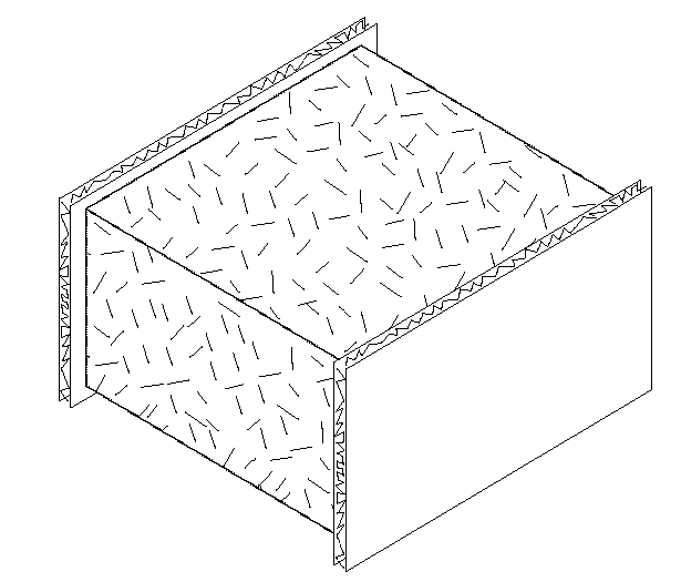
Both the percent of concrete web and the percent steel are factors in determining the thermal performance of walls. The insulation layer in this type of concrete sandwich panel generally does not extend over the entire surface of the wall. To provide structural integrity, a certain portion of the wall is solid concrete, which ties together the two concrete layers. This portion is known as the concrete web. The thermal performance of concrete sandwich panels depends on the percent of the wall that is concrete web. Data is provided for concrete webs representing 0 percent, 10 percent and 20 percent of the opaque wall surface. In some cases, the concrete layers are tied together by structural steel that penetrates the insulation layer. Data is provided for the case where this steel is present and for cases where it is not.
|
Percent Concrete Web |
Steel Penetrates Insulation |
Performance Factor |
|
Insulation Thickness (R-value) | ||||
|
|
1.5 (7.0) |
2.0 (9.3) |
3.0 (14.0) |
4.0 (18.6) |
6.0 (27.9) | |||
|
|
A |
B |
C |
D |
E | |||
|
0% |
No |
U-factor |
1 |
0.122 |
0.095 |
0.066 |
0.051 |
0.034 |
|
C-factor |
0.136 |
0.104 |
0.070 |
0.053 |
0.035 | |||
|
HC |
16.13 |
16.13 |
16.13 |
16.13 |
16.13 | |||
|
Yes |
U-factor |
2 |
0.164 |
0.128 |
0.091 |
0.070 |
0.048 | |
|
C-factor |
0.190 |
0.144 |
0.099 |
0.074 |
0.050 | |||
|
HC |
16.13 |
16.13 |
16.13 |
16.13 |
16.13 | |||
|
10% |
No |
U-factor |
3 |
0.476 |
0.435 |
0.345 |
0.286 |
0.217 |
|
C-factor |
0.800 |
0.690 |
0.488 |
0.377 |
0.267 | |||
|
HC |
16.53 |
16.66 |
16.93 |
17.20 |
17.74 | |||
|
Yes |
U-factor |
4 |
0.500 |
0.435 |
0.357 |
0.303 |
0.227 | |
|
C-factor |
0.870 |
0.690 |
0.513 |
0.408 |
0.282 | |||
|
HC |
16.53 |
16.66 |
16.93 |
17.20 |
17.74 | |||
|
20% |
No |
U-factor |
5 |
0.588 |
0.556 |
0.476 |
0.417 |
0.333 |
|
C-factor |
1.176 |
1.053 |
0.800 |
0.645 |
0.465 | |||
|
HC |
16.93 |
17.20 |
17.74 |
18.28 |
19.35 | |||
|
Yes |
U-factor |
6 |
0.588 |
0.556 |
0.476 |
0.417 |
0.333 | |
|
C-factor |
1.176 |
1.053 |
0.800 |
0.645 |
0.465 | |||
|
HC |
16.93 |
17.20 |
17.74 |
18.28 |
19.35 | |||
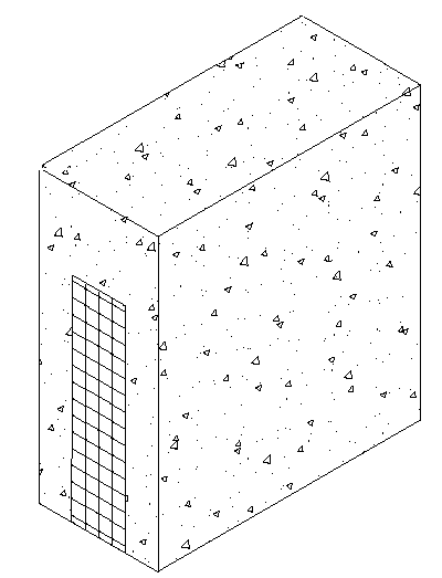
This table provides U-factors, C-factors, and heat capacity (HC) data for concrete sandwich panels. Concrete sandwich panels, as the name suggests, consist of two layers of concrete that sandwich a layer of insulation. The wall system can be constructed in the field or in a factory. One method of field construction is where the wall panels are formed in a flat position using the concrete floor slab of the building as the bottom surface. After the panel has set, it is hoisted with a crane into its final vertical position.
Both the percent of concrete web and the percent steel are factors in determining the thermal performance of walls. The insulation layer in this type of concrete sandwich panel generally does not extend over the entire surface of the wall. To provide structural integrity, a certain portion of the wall is solid concrete, which ties together the two concrete layers. This portion is known as the concrete web. The thermal performance of concrete sandwich panels depends on the percent of the wall that is concrete web. Data is provided for concrete webs representing 0 percent, 10 percent and 20 percent of the opaque wall surface. In some cases, the concrete layers are tied together by structural steel that penetrates the insulation layer. Data is provided for the case where this steel is present and for cases where it is not.
Other properties of mass materials such as density, conductivity, specific heat and wall weight may be needed in compliance calculations and these properties may be determined from the published data in Table 4.3.7 using the procedures in Modeling Constructions in the Nonresidential compliance software and in Section 4.6 of this document.
Values from this table may be combined with values from Table 4.3.14 when a furring layer is added to the inside of the wall and/or continuous insulation is added to the outside of the wall. Adjustments for additional layers shall follow the procedure of Equation 4-4 and Equation 4-5.
Assumptions: U-factors include an inside air film of 0.68 and an exterior air film of 0.17. Conductivity of the concrete is assumed to be 0.215 Btu/h-ºF-f, density is 150 lb/ft³, the thickness of each side of the sandwich panel is 0.5 ft. The data was calculated by Construction Technologies Laboratories, Inc. and published in the Thermal Mass Handbook, Concrete and Masonry Design Provisions Using ASHRAE/IESNA 90.1-1989, National Codes and Standards Council of the Concrete and Masonry Industries, 1994.
|
|
|
|
Rated R-value of Insulation between Framing Members | |||||||
|
|
|
|
None |
R-4 |
R-7 |
R-10 |
R-15 |
R-20 |
R-25 |
R-30 |
|
Frame Type |
Spandrel Panel |
|
A |
B |
C |
D |
E |
F |
G |
H |
|
Aluminum without Thermal Break |
Single glass pane, stone, or metal panel |
1 |
0.360 |
0.242 |
0.222 |
0.212 |
0.203 |
0.198 |
0.195 |
0.193 |
|
Double glass with no low-e coatings |
2 |
0.297 |
0.233 |
0.218 |
0.209 |
0.202 |
0.197 |
0.194 |
0.192 | |
|
Triple or low-e glass |
3 |
0.267 |
0.226 |
0.214 |
0.207 |
0.200 |
0.196 |
0.194 |
0.192 | |
|
Aluminum with Thermal Break |
Single glass pane, stone, or metal panel |
4 |
0.350 |
0.211 |
0.186 |
0.173 |
0.162 |
0.155 |
0.151 |
0.149 |
|
Double glass with no low-e coatings |
5 |
0.278 |
0.200 |
0.180 |
0.170 |
0.160 |
0.154 |
0.151 |
0.148 | |
|
Triple or low-e glass |
6 |
0.241 |
0.191 |
0.176 |
0.167 |
0.159 |
0.153 |
0.150 |
0.148 | |
|
Structural Glazing |
Single glass pane, stone, or metal panel |
7 |
0.354 |
0.195 |
0.163 |
0.147 |
0.132 |
0.123 |
0.118 |
0.114 |
|
Double glass with no low-e coatings |
8 |
0.274 |
0.180 |
0.156 |
0.142 |
0.129 |
0.122 |
0.117 |
0.114 | |
|
Triple or low-e glass |
9 |
0.231 |
0.169 |
0.150 |
0.138 |
0.127 |
0.121 |
0.116 |
0.113 | |
|
No framing or Insulation is Continuous |
Single glass pane, stone, or metal panel |
10 |
0.360 |
0.148 |
0.102 |
0.078 |
0.056 |
0.044 |
0.036 |
0.031 |
|
Double glass with no low-e coatings |
11 |
0.297 |
0.136 |
0.097 |
0.075 |
0.054 |
0.043 |
0.035 |
0.030 | |
|
Triple or low-e glass |
12 |
0.267 |
0.129 |
0.093 |
0.073 |
0.053 |
0.042 |
0.035 |
0.030 | |
This table has U-factors for the spandrel section of glass and other curtain wall systems. Design factors that affect performance are the type of framing, the type of spandrel panel and the R-value of insulation.
Four framing conditions are considered in the table. The first is the common case where standard aluminum mullions are used. Standard mullions provide a thermal bridge through the insulation, reducing its effectiveness. The second case is for metal framing members that have a thermal break. A thermal break frame uses a urethane or other non-metallic element to separate the metal exposed to outside conditions from the metal that is exposed to interior conditions. The third case is for structural glazing or systems where there is no exposed mullion on the interior. The fourth case is for the condition where there is no framing or the insulation is continuous and uninterrupted by framing. The columns in the table can be used for any specified level of insulation between framing members installed in framed curtain walls or spandrel panels.

There are three spandrel panel cases considered in the table. The first is for a panel that provides little or no insulating value. This includes single pane glass, stone veneer, metal panels, or pre-case concrete less than 2 inches thick. The second case is for insulating glass. Sometimes insulating glass is used so that the spandrel panel looks similar to the vision glass. The third case is for triple glass or double glass that has a low-e coating.
Insulation levels are shown in the columns of the table. When the table is used manually, the R-value of insulation shall be equal to or greater than the R-value published in the columns. No interpolation is permitted when data from the table is selected manually. California Energy Commission approved compliance software programs, including those used for prescriptive compliance, may accurately account for any amount of continuous insulation or for unusual construction assemblies using Equation 4-1 and Equation 4-2. If the curtain wall has an insulated metal-framed wall on the inside, then values from this table may be combined with values from Table 4.3.4 or Table 4.3.14 using the procedures of Equation 4-2 or Equation 4-3.
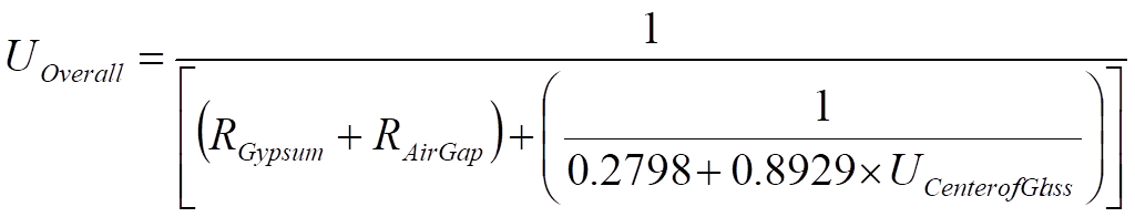
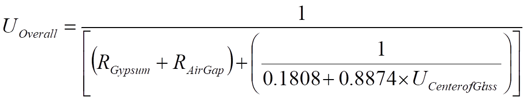
Assumptions: The U-factors in Table 4.3.8 were derived from a regression analysis of the values for “Glass Only Center of Glass” and “Curtain Wall” in the 2009 ASHRAE Handbook of Fundamentals, Chapter 15, Table 4. The U-factors in Table 4.3.8 include an exterior air film with an R-value of 0.17 and an interior air film R-value of 0.68, which are accounted for in the values from the 2009
ASHRAE Handbook of Fundamentals. The construction assembly consists of the Frame Type and Spandrel Panel combinations 'listed in Table 4.3.8, an air gap with an R-value of 1.39 (3/4 inch gap, 50 ºF mean temperature and 30 ºF temperature difference), and 5/8 inch gypsum board with an R-value of 0.56 that provides the interior finish. The gypsum board is assumed to span between the window sill and a channel at the floor.
The following equations were used when no rigid insulation is added to the assembly.
Aluminum Without Thermal Break
Equation 4-6
Aluminum With Thermal Break
Equation 4-7
Equation 4-8
Structural Glazing
The following equations were used when rigid insulation is added to the assembly.
Aluminum Without Thermal Break
Equation 4-9

Equation 4-10
Aluminum With Thermal Break
Equation 4-11
Structural Glazing
|
Insulation System |
Rated R-Value of Insulation |
Continuous Rigid Insulation |
| ||||||||
|
|
None |
R-2 |
R-4 |
R-6 |
R-7 |
R-8 |
R-10 |
R-14 | |||
|
|
A |
B |
C |
D |
E |
F |
G |
H | |||
|
Single Layer of Batt Insulation |
None |
1 |
1.18 |
0.351 |
0.206 |
0.146 |
0.127 |
0.113 |
0.092 |
0.067 | |
|
R-6 |
2 |
0.184 |
0.135 |
0.106 |
0.087 |
0.080 |
0.074 |
0.065 |
0.051 | ||
|
R-10 |
3 |
0.134 |
0.106 |
0.087 |
0.074 |
0.069 |
0.065 |
0.057 |
0.047 | ||
|
R-11 |
4 |
0.123 |
0.099 |
0.082 |
0.071 |
0.066 |
0.062 |
0.055 |
0.045 | ||
|
R-13 |
5 |
0.113 |
0.092 |
0.078 |
0.067 |
0.063 |
0.059 |
0.053 |
0.044 | ||
|
Double Layer of Batt Insulation |
R-6 + R-13 |
6 |
0.07 |
0.061 |
0.055 |
0.049 |
0.047 |
0.045 |
0.041 |
0.035 | |
|
R-10 + R-13 |
7 |
0.061 |
0.054 |
0.049 |
0.045 |
0.043 |
0.041 |
0.038 |
0.033 | ||
|
R-13 + R-13 |
8 |
0.057 |
0.051 |
0.046 |
0.042 |
0.041 |
0.039 |
0.036 |
0.032 | ||
|
R-19 + R-13 |
9 |
0.048 |
0.044 |
0.040 |
0.037 |
0.036 |
0.035 |
0.032 |
0.029 | ||
Double layer or batt insulation may not be able to have Continuous rigid insulation added.
The U-factors in this table are intended for use with metal building walls. This type of construction is typical for manufacturing and warehouse facilities, but is used for other building types as well. The typical method of insulating this type of building is to stretch vinyl backed fiberglass insulation over the metal girts before the metal siding is attached with metal screws. With this method, the insulation is compressed at each girt, reducing its effectiveness. The first part of the table contains values for this insulation technique. The second section of the table has data for systems that have two layers of insulation. In this section layers are listed from inside to outside.
For the majority of cases, values will be selected from column A of this table. Builders or designers may increase thermal performance by adding a rigid continuous insulation layer between the metal siding and the structural supports. When this table is used manually, the R-value of continuous insulation shall be equal to or greater than the R-value published in the continuous insulation columns. No interpolation is permitted when data from the table is used manually. Energy Commission approved compliance software, however, may determine the U-factor for any amount of continuous insulation using Equation 4-1.
Assumptions: Data in Column A of this table is taken from the ASHRAE/IESNA Standard 90.1-2004, Appendix A. The data in columns beyond A are calculated using Equation 4-1.
|
|
|
U-factor (Btu/0F-ft2) |
|
Panel Thickness |
|
A |
|
2” |
1 |
0.078 |
|
2 ½” |
2 |
0.063 |
|
3” |
3 |
0.053 |
|
4” |
4 |
0.041 |
|
5” |
5 |
0.033 |
|
6” |
6 |
0.027 |
This table contains thermal performance data (U-factors) for foamed-in-place, insulated metal panels consisting of liquid polyurethane or polyisocyanurate injected between metal skins in individual molds or on fully automated production lines. Metal building construction is the most common application for this product where the metal panel is fastened to the frame of the structure. This table can only be used for insulated panels that are factory built. This table does not apply to panels that utilize polystyrene, or to field applied products such as spray applied insulations.
Assumptions. These data are calculated using the parallel path method documented in the 2009 ASHRAE Handbook of Fundamentals. These calculations assume an exterior air film of R-0.17, light gauge metal exterior of 0.0747 inch thickness, continuous insulation R-5.9 per inch, light gauge metal interior of 0.0747 inch thickness, interior air film (heat flow horizontal) of R-0.68. The panels are assumed to be continuous with no framing penetration. The R-value of the metal is negligible.
|
|
|
U-factor |
Heat Capacity (HC) |
|
Log Diameter |
|
A | |
|
6” |
1 |
0.133 |
4.04 |
|
8” |
2 |
0.102 |
6.06 |
|
10” |
3 |
0.083 |
6.73 |
|
12” |
4 |
0.070 |
8.08 |
|
14” |
5 |
0.060 |
9.42 |
|
16” |
6 |
0.053 |
10.77 |
This table has U-factors and heat capacity data for log homes Data is provided for logs in six thicknesses ranging from 6 in. to 16 in. If other thermal properties are needed such as density, weight, conductivity, etc., use the procedures in Modeling Constructions in the Nonresidential compliance software and contained in Section 4.6 of this document. Energy Commission approved Compliance Software Programs may adjust the data for interior furring using data from Table 4.3.14 and the procedure from Equation 4-2.

Assumptions: Calculations are based on ASHRAE series method of calculation, 2009 ASHRAE Handbook of Fundamentals. Values assume a log R-value of R-1.25/inch, an average wall thickness of 90 percent of the log diameter, an interior air film of R-0.68 and an exterior air film of R-0.17. Values do not account for presence of windows or doors. Construction assumes no additional siding or insulation. Heat Capacity is based on a hardwood density of 26.6 lb/ft³ and a specific heat of 0.39 Btu/lb-ºF. An exterior air film of R-0.17 and an interior film of R-0.68 are assumed.
|
|
|
A |
|
R-value |
1 |
30 |
|
U-factor |
0.033 | |
|
Heat Capacity Btu/ft2*°F] |
2.24 |
This table has data that may be used for straw bale construction. This is an alternative construction technique used in some rural areas. The technique is not commonly used for production homes.
Assumptions: The construction consists of an exterior film of R-0.17, stucco and lath of R-0.18, the straw bale, interior plaster of R-0.47, and an interior air film of 0.68. Straw bale must have a minimum cross section of 22 inch by 16 inch, and shall have a thermal resistance of R-30, whether stacked so the walls are 23 inch wide or 16 inch wide. Due to the higher resistance to heat flow across the grain of the straws, a bale laid on edge with a nominal 16 inch horizontal thickness has the same R-value (R-30) as a bale laid flat. Framing is assumed to not penetrate more than 25 percent of the way through the straw bale.
Table 4.3.13 – Thermal Properties of Insulating Concrete Forms
|
Insulation Type |
Insulation Thickness Per Side (Total R-Value) |
Performance Factor |
|
Flat1 |
Waffle Grid2 |
Screen Grid2 | |||||
|
|
Concrete Core Thickness (inches) | ||||||||||
|
|
4 |
6 |
8 |
10 |
12 |
6 |
8 |
6 | |||
|
|
A |
B |
C |
D |
E |
F |
G |
H | |||
|
EPS3 |
2.0 (15.4) |
U-factor HC |
1 |
0.058 12.20 |
0.057 17.00 |
0.056 21.80 |
0.055 26.60 |
0.055 31.40 |
0.047 13.90 |
0.039 15.87 |
0.041 12.10 |
|
2.25 (18.9) |
U-factor HC |
2 |
0.052 12.22 |
0.051 17.02 |
0.051 21.82 |
0.050 26.62 |
0.050 31.42 |
0.043 13.92 |
0.036 15.89 |
0.038 12.11 | |
|
2.5 (19.25) |
U-factor HC |
3 |
0.047 12.24 |
0.047 17.04 |
0.046 21.84 |
0.046 26.64 |
0.045 31.44 |
0.040 13.94 |
0.034 15.91 |
0.036 12.13 | |
|
2.625 (20.2) |
U-factor HC |
4 |
0.045 12.25 |
0.045 17.05 |
0.044 21.85 |
0.044 26.65 |
0.043 31.45 |
0.038 13.95 |
0.033 15.92 |
0.035 12.14 | |
|
2.75 (21.2) |
U-factor HC |
5 |
0.043 12.26 |
0.043 17.06 |
0.042 21.86 |
0.042 26.66 |
0.042 31.46 |
0.037 13.96 |
0.032 15.92 |
0.0323 12.15 | |
|
3.0 (23.1) |
U-factor HC |
6 |
0.040 12.27 |
0.040 17.07 |
0.039 21.87 |
0.039 26.67 |
0.039 31.47 |
0.0334 13.98 |
0.030 15.94 |
0.031 12.17 | |
|
3.5 (27.0) |
U-factor HC |
7 |
0.035 12.31 |
0.034 17.11 |
0.034 21.91 |
0.034 26.71 |
0.034 31.51 |
0.030 14.01 |
0.027 15.98 |
0.028 12.21 | |
|
4.0 (30.8) |
U-factor HC |
8 |
0.031 12.35 |
0.030 17.15 |
0.030 21.95 |
0.030 26.75 |
0.030 31.55 |
0.027 14.05 |
0.024 16.02 |
0.025 12.24 | |
|
XPS |
2.0 (20.0) |
U-factor HC |
9 |
0.045 12.29 |
0.045 17.09 |
0.045 21.89 |
0.044 26.69 |
0.044 31.49 |
NA NA |
NA NA |
NA NA |
|
2.5 (25.0) |
U-factor HC |
10 |
0.037 12.35 |
0.037 17.15 |
0.036 21.95 |
0.036 26.75 |
0.036 31.55 |
NA NA |
NA NA |
NA NA | |
|
2.625 (26.3) |
U-factor HC |
11 |
0.035 12.36 |
0.035 17.16 |
0.035 21.96 |
0.035 26.76 |
0.034 31.56 |
NA NA |
NA NA |
NA NA | |
|
2.75 (27.5) |
U-factor HC |
12 |
0.034 12.38 |
0.034 17.18 |
0.033 21.98 |
0.033 26.78 |
0.033 31.58 |
NA NA |
NA NA |
NA NA | |
|
3.0 (30.0) |
U-factor HC |
13 |
0.031 12.41 |
0.031 17.21 |
0.031 22.01 |
0.031 26.81 |
0.030 31.61 |
NA NA |
NA NA |
NA NA | |
|
3.5 (35.0) |
U-factor HC |
14 |
0.027 12.46 |
0.027 17.26 |
0.027 22.06 |
0.027 26.86 |
0.026 31.66 |
NA NA |
NA NA |
NA NA | |
|
4.0 (40) |
U-factor HC |
15 |
0.024 12.52 |
0.024 17.32 |
0.024 22.12 |
0.023 26.92 |
0.023 31.72 |
NA NA |
NA NA |
NA NA | |
|
Polyurethane |
1.5 (9.09) |
U-factor HC |
16 |
0.050 12.23 |
0.049 17.03 |
0.049 21.83 |
0.048 26.63 |
0.048 31.43 |
NA NA |
NA NA |
NA NA |
|
2.0 (10.9) |
U-factor HC |
17 |
0.042 12.41 |
0.042 17.21 |
0.041 22.01 |
0.041 26.81 |
0.041 31.61 |
NA NA |
NA NA |
NA NA | |
|
4.5 (20.95) |
U-factor HC |
18 |
0.023 12.58 |
0.023 17.38 |
0.023 22.18 |
0.022 26.98 |
0.022 31.78 |
NA NA |
NA NA |
NA NA | |
|
Cement/EPS Compound |
2.0 (12.0) |
U-factor HC |
19 |
NA NA |
NA NA |
NA NA |
NA NA |
NA NA |
0.059 16.49 |
0.048 18.46 |
0.052 14.69 |
|
3.0 (18.0) |
U-factor HC |
20 |
NA NA |
NA NA |
NA NA |
NA NA |
NA NA |
0.043 17.50 |
0.037 19.47 |
0.040 15.69 | |
|
4.0 (24.0) |
U-factor HC |
21 |
NA NA |
NA NA |
NA NA |
NA NA |
NA NA |
0.034 18.51 |
0.031 20.47 |
0.032 16.70 | |
|
Notes: |
|
|
|
|
|
|
|
|
|
|
|
|
1 Flat Insulated Concrete Forms utilizes rigid insulation as the form and do not use cement compound as the form. | |||||||||||
|
2 Waffle and screen type Insulated Concrete Forms typically utilize either a cement/EPS compound or EPS insulation as the form. ICF's using the cement/EPS compound do not utilize rigid insulation added to the interior and exterior surfaces. 3 1.5 lb density EPS insulation at R-3.85 per inch except for the 2.25” insulation thickness which uses 2.0 lb density EPS at R-4.2 per inch. | |||||||||||
This table provides thermal performance information for insulating concrete forms.
Insulating Concrete Forms (ICFs) are concrete forming systems that use stay-in-place panels made from a variety of insulating materials for constructing cast-in-place solid concrete walls. There are three basic types of ICFs: flat wall, waffle-grid and screen-grid. A flat wall system is a wall with uniform thickness just like a conventional poured wall made with plywood or metal forms. Waffle-grid wall systems have a solid concrete wall of varying thickness and look like a breakfast waffle. Screen grid wall systems also known as , “post and beam”, have a perforated concrete wall of varying thickness similar to the waffle type wall systems but with a solid form material between the horizontal and vertical members instead of concrete. The insulating panels for all three ICF types are most commonly made from expanded polystyrene (EPS) and extruded polystyrene (XPS) rigid insulation boards. Plastic or metal cross-ties separate the insulating panels and provide structural integrity during the pour. The ICF system is modular and stackable with interlocking edges. The materials can be delivered as pre-assembled blocks or as planks that require the flanges and web to be assembled during construction.

Assumptions: Values in this table were calculated using the one dimensional calculation method documented in 2009 ASHRAE Handbook of Fundamentals. The calculations assume an exterior air film of R-0.17, a 7/8 inch layer of stucco of R-0.18, building paper of R-0.06, an exterior insulating form of varying resistance, a concrete core of varying thickness at R-0.11 per inch, an interior insulating form of varying resistance, and an interior air film of R-0.68. The R-value of the cement/EPC compound is assumed to be R-3.0 per inch, the XPS insulation assumed to be R-5.0 per inch, and the polyurethane assumed to be aged and dried in 1.5 inch, 2.0 inch, and 4.5 inch thickness.
|
Thick-ness |
Frame Type |
|
R-value of Insulation Installed in Furring Space | |||||||||||||||||||||
|
|
0 |
1 |
2 |
3 |
4 |
5 |
6 |
7 |
8 |
9 |
10 |
11 |
12 |
13 |
14 |
15 |
16 |
17 |
18 |
19 |
20 |
21 | ||
|
|
A |
B |
C |
D |
E |
F |
G |
H |
I |
J |
K |
L |
M |
N |
O |
P |
Q |
R |
S |
T |
U |
V | ||
|
Any |
None |
1 |
0.5 |
1.5 |
2.5 |
3.5 |
4.5 |
5.5 |
6.5 |
7.5 |
8.5 |
9.5 |
10.5 |
11.5 |
12.5 |
13.5 |
14.5 |
15.5 |
16.5 |
17.5 |
18.5 |
19.5 |
20.5 |
21.5 |
|
0.5" |
Wood |
2 |
1.3 |
1.3 |
1.9 |
2.4 |
2.7 |
n.a. |
n.a. |
n.a. |
n.a. |
n.a. |
n.a. |
n.a. |
n.a. |
n.a. |
n.a. |
n.a. |
n.a. |
n.a. |
n.a. |
n.a. |
n.a. |
n.a. |
|
|
Metal |
3 |
0.9 |
0.9 |
1.1 |
1.1 |
1.2 |
n.a. |
n.a. |
n.a. |
n.a. |
n.a. |
n.a. |
n.a. |
n.a. |
n.a. |
n.a. |
n.a. |
n.a. |
n.a. |
n.a. |
n.a. |
n.a. |
n.a. |
|
0.75" |
Wood |
4 |
1.4 |
1.4 |
2.1 |
2.7 |
3.1 |
3.5 |
3.8 |
n.a. |
n.a. |
n.a. |
n.a. |
n.a. |
n.a. |
n.a. |
n.a. |
n.a. |
n.a. |
n.a. |
n.a. |
n.a. |
n.a. |
n.a. |
|
|
Metal |
5 |
1.0 |
1.0 |
1.3 |
1.4 |
1.5 |
1.5 |
1.6 |
n.a. |
n.a. |
n.a. |
n.a. |
n.a. |
n.a. |
n.a. |
n.a. |
n.a. |
n.a. |
n.a. |
n.a. |
n.a. |
n.a. |
n.a. |
|
1.0" |
Wood |
6 |
1.3 |
1.5 |
2.2 |
2.9 |
3.4 |
3.9 |
4.3 |
4.6 |
4.9 |
n.a. |
n.a. |
n.a. |
n.a. |
n.a. |
n.a. |
n.a. |
n.a. |
n.a. |
n.a. |
n.a. |
n.a. |
n.a. |
|
|
Metal |
7 |
1.0 |
1.1 |
1.4 |
1.6 |
1.7 |
1.8 |
1.8 |
1.9 |
1.9 |
n.a. |
n.a. |
n.a. |
n.a. |
n.a. |
n.a. |
n.a. |
n.a. |
n.a. |
n.a. |
n.a. |
n.a. |
n.a. |
|
1.5" |
Wood |
8 |
1.3 |
1.5 |
2.4 |
3.1 |
3.8 |
4.4 |
4.9 |
5.4 |
5.8 |
6.2 |
6.5 |
6.8 |
7.1 |
n.a. |
n.a. |
n.a. |
n.a. |
n.a. |
n.a. |
n.a. |
n.a. |
n.a. |
|
|
Metal |
9 |
1.1 |
1.2 |
1.6 |
1.9 |
2.1 |
2.2 |
2.3 |
2.4 |
2.5 |
2.5 |
2.6 |
2.6 |
2.7 |
n.a. |
n.a. |
n.a. |
n.a. |
n.a. |
n.a. |
n.a. |
n.a. |
n.a. |
|
2" |
Wood |
10 |
1.4 |
1.5 |
2.5 |
3.3 |
4.0 |
4.7 |
5.3 |
5.9 |
6.4 |
6.9 |
7.3 |
7.7 |
8.1 |
8.4 |
8.7 |
9.0 |
9.3 |
n.a. |
n.a. |
n.a. |
n.a. |
n.a. |
|
|
Metal |
11 |
1.1 |
1.2 |
1.7 |
2.1 |
2.3 |
2.5 |
2.7 |
2.8 |
2.9 |
3.0 |
3.1 |
3.2 |
3.2 |
3.3 |
3.3 |
3.4 |
3.4 |
n.a. |
n.a. |
n.a. |
n.a. |
n.a. |
|
2.5" |
Wood |
12 |
1.4 |
1.5 |
2.5 |
3.4 |
4.2 |
4.9 |
5.6 |
6.3 |
6.8 |
7.4 |
7.9 |
8.4 |
8.8 |
9.2 |
9.6 |
10.0 |
10.3 |
10.6 |
10.9 |
11.2 |
11.5 |
n.a. |
|
|
Metal |
13 |
1.2 |
1.3 |
1.8 |
2.3 |
2.6 |
2.8 |
3.0 |
3.2 |
3.3 |
3.5 |
3.6 |
3.6 |
3.7 |
3.8 |
3.9 |
3.9 |
4.0 |
4.0 |
4.1 |
4.1 |
4.1 |
n.a. |
|
3" |
Wood |
14 |
1.4 |
1.5 |
2.5 |
3.5 |
4.3 |
5.1 |
5.8 |
6.5 |
7.2 |
7.8 |
8.3 |
8.9 |
9.4 |
9.9 |
10.3 |
10.7 |
11.1 |
11.5 |
11.9 |
12.2 |
12.5 |
12.9 |
|
|
Metal |
15 |
1.2 |
1.3 |
1.9 |
2.4 |
2.8 |
3.1 |
3.3 |
3.5 |
3.7 |
3.8 |
4.0 |
4.1 |
4.2 |
4.3 |
4.4 |
4.4 |
4.5 |
4.6 |
4.6 |
4.7 |
4.7 |
4.8 |
|
3.5" |
Wood |
16 |
1.4 |
1.5 |
2.6 |
3.5 |
4.4 |
5.2 |
6.0 |
6.7 |
7.4 |
8.1 |
8.7 |
9.3 |
9.8 |
10.4 |
10.9 |
11.3 |
11.8 |
12.2 |
12.6 |
13.0 |
13.4 |
13.8 |
|
|
Metal |
17 |
1.2 |
1.3 |
2.0 |
2.5 |
2.9 |
3.2 |
3.5 |
3.8 |
4.0 |
4.2 |
4.3 |
4.5 |
4.6 |
4.7 |
4.8 |
4.9 |
5.0 |
5.1 |
5.1 |
5.2 |
5.2 |
5.3 |
|
4" |
Wood |
18 |
1.4 |
1.6 |
2.6 |
3.6 |
4.5 |
5.3 |
6.1 |
6.9 |
7.6 |
8.3 |
9.0 |
9.6 |
10.2 |
10.8 |
11.3 |
11.9 |
12.4 |
12.8 |
13.3 |
13.7 |
14.2 |
14.6 |
|
|
Metal |
19 |
1.2 |
1.3 |
2.0 |
2.6 |
3.0 |
3.4 |
3.7 |
4.0 |
4.2 |
4.5 |
4.6 |
4.8 |
5.0 |
5.1 |
5.2 |
5.3 |
5.4 |
5.5 |
5.6 |
5.7 |
5.8 |
5.8 |
|
4.5" |
Wood |
20 |
1.4 |
1.6 |
2.6 |
3.6 |
4.5 |
5.4 |
6.2 |
7.1 |
7.8 |
8.5 |
9.2 |
9.9 |
10.5 |
11.2 |
11.7 |
12.3 |
12.8 |
13.3 |
13.8 |
14.3 |
14.8 |
15.2 |
|
|
Metal |
21 |
1.2 |
1.3 |
2.1 |
2.6 |
3.1 |
3.5 |
3.9 |
4.2 |
4.5 |
4.7 |
4.9 |
5.1 |
5.3 |
5.4 |
5.6 |
5.7 |
5.8 |
5.9 |
6.0 |
6.1 |
6.2 |
6.3 |
|
5" |
Wood |
22 |
1.4 |
1.6 |
2.6 |
3.6 |
4.6 |
5.5 |
6.3 |
7.2 |
8 |
8.7 |
9.4 |
10.1 |
10.8 |
11.5 |
12.1 |
12.7 |
13.2 |
13.8 |
14.3 |
14.8 |
15.3 |
15.8 |
|
|
Metal |
23 |
1.2 |
1.4 |
2.1 |
2.7 |
3.2 |
3.7 |
4.1 |
4.4 |
4.7 |
5.0 |
5.2 |
5.4 |
5.6 |
5.8 |
5.9 |
6.1 |
6.2 |
6.3 |
6.5 |
6.6 |
6.7 |
6.8 |
|
5.5" |
Wood |
24 |
1.4 |
1.6 |
2.6 |
3.6 |
4.6 |
5.5 |
6.4 |
7.3 |
8.1 |
8.9 |
9.6 |
10.3 |
11.0 |
11.7 |
12.4 |
13.0 |
13.6 |
14.2 |
14.7 |
15.3 |
15.8 |
16.3 |
|
|
Metal |
25 |
1.3 |
1.4 |
2.1 |
2.8 |
3.3 |
3.8 |
4.2 |
4.6 |
4.9 |
5.2 |
5.4 |
5.7 |
5.9 |
6.1 |
6.3 |
6.4 |
6.6 |
6.7 |
6.8 |
7.0 |
7.1 |
7.2 |
|
EIFS |
|
26 |
0.0 |
1.0 |
2.0 |
3.0 |
4.0 |
5.0 |
6.0 |
7.0 |
8.0 |
9.0 |
10.0 |
11.0 |
12.0 |
13.0 |
14.0 |
15.0 |
16.0 |
17.0 |
18.0 |
19.0 |
20.0 |
21.0 |
|
Metal Clips
|
Wood Framing
|
This table is used in combination with other tables and Equation 4-1 and Equation 4-2 to account for interior furring and continuous insulation added to other constructions.
Assumptions: Data is taken from ASHRAE/IESNA Standard 90.1-2004 All furring thickness values given are actual dimensions. All values include 0.5 inch gypsum board on the inner surface, interior surface resistances not included. The metal furring is 24 inch on center, 24 gauge, Z-type Metal Furring. The wood furring is 24 inch on center, Douglas-Fir Larch Wood Furring, density = 34.9 lb/ft³. Insulation assumed to fill the furring space.


