
Air conditioning systems shall be sized, installed, tested and modeled according to the provisions of this section.
The Compliance Software calculates the hourly cooling electricity consumption in kWh using Equation 219. In this equation, the energy for the air handler fan and the electric compressor or parasitic power for the outdoor unit of a gas absorption air conditioner are combined. The Compliance Software calculates the hourly cooling gas consumption in therms using Equation 219
Equation 219
Where:
ACkWh = Air conditioner kWh of electricity consumption for a particular hour of the simulation. This value is calculated for each hour, combined with the TDV multipliers, and summed for the year.
FanWh = Indoor fan electrical energy for a particular hour of the simulation, Wh.
CompWh = Electrical energy for all components except the indoor fan for a particular hour of the simulation, Wh. This value includes consumption for the compressor plus outdoor condenser fan and is calculated using Equation 221.
CSE calculates the energy for electrically driven cooling using the algorithms described in this section.
Primary model parameters. The following values characterize the AC unit and are constant for a given unit:
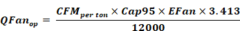
Cap95 = AHRI rated total cooling capacity at 95 °F, Btuh
CFMper ton = Air flow rate per ton of cooling capacity, cfm/ton.
EFan = Fan operating electrical power, W/cfm. Default = 0.365.
SEER = AHRI rated Seasonal Energy Efficiency Ratio, Btuh/W. EER shall be used in lieu of the SEER for equipment not required to be tested for a SEER rating.
EER = AHRI rated energy efficiency ratio at 95 °F, Btuh/W. If EER is not available, it is derived from SEER as follows:
|
If SEER |
>=16 |
>=13 & <16 |
<13 |
|
EER |
13 |
11.3 + 0.57 x (SEER-13) |
10+0.84×(SEER– 11.5) |
Fchg = Refrigerant charge factor, default = 0.9. For systems with a verified charge indicator light (Reference Residential Appendix RA3.4) or verified refrigerant charge (Reference Residential Appendix RA3), the factor shall be 0.96.
Fsize = Compressor sizing factor, default = 0.95. For systems sized according to the Maximum Cooling Capacity for compliance software Credit (see Section <TODO>), the factor shall be 1.0.
Derived model parameters. The following values are used in the formulas below and depend only on model parameters.
Tons = Nominal cooling capacity defined as Cap95 / 12000
QFanrat = Assumed fan heat included at AHRI test conditions, Btuh
|
Fan motor type |
QFanrat |
|
PSC |
500 x Cap95 / 12000 |
|
BPM |
283 x Cap95 / 12000 |
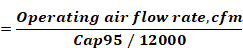
QFanop = Fan heat assumed during operation (i.e., during simulation), Btuh
Equation 220
Model inputs. The following values vary at each time step in the simulation and are used in the formulas below to determine AC unit performance under for that time step.
DBt = Dry bulb temperature of air at the condensing unit, °F (typically outdoor air temperature).
WBec = Coil entering air wet bulb temperature, °F (return air temperature adjusted for blow-through fan heat if any)
DBec = Coil entering air dry bulb temperature, °F (return air temperature adjusted for blow through fan heat if any)
Qneed = Cooling system sensible cooling output, Btuh. Qneed is calculated across the unit and thus includes both the building load and distribution losses.
Compressor energy for a particular time step of the simulation shall be calculated using Equation 221.
Equation 221

Where:
Fanwh = Fan power for this time step, Wh.
CEt = Sensible energy efficiency at current conditions, Btuh/W. This is calculated using Equation 222 below.
Equation 222
Where:
EERt = Energy efficiency ratio at current conditions, Btuh/W. EERt is calculated using Equation 226 below.
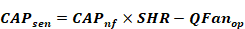
SHR = Sensible Heat Ratio (sensible capacity / total capacity), derived as follows:
SHR = minimum(1, ASHR × DBec +
BSHR × WBec +
CSHR × DBt +
DSHR × CFMper ton +
ESHR × DBec × DBt +
FSHR × DBec × CFMper ton +
GSHR × WBec × DBt +
HSHR × WBec × CFMper ton +
ISHR × DBt × CFMper ton +
JSHR × WBec2 +
KSHR / CFMper ton +
LSHR)
SHR coefficients:
|
ASHR |
0.0242020 |
|
BSHR |
-0.0592153 |
|
CSHR |
0.0012651 |
|
DSHR |
0.0016375 |
|
ESHR |
0 |
|
FSHR |
0 |
|
GSHR |
0 |
|
HSHR |
-0.0000165 |
|
ISHR |
0 |
|
JSHR |
0.0002021 |
|
KSHR |
0 |
|
LSHR |
1.5085285 |
CAPnf = Total cooling capacity across coil (that is, without fan heat) at current conditions, Btuh
Equation 223

Fcond_cap = ACAP × DBec +
BCAP × WBec +
CCAP × DBt +
DCAP × CFMper ton +
ECAP × DBec × DBt +
FCAP × DBec × CFMper ton +
GCAP × WBec × DBt +
HCAP × WBec × CFMper ton +
ICAP × DBt × CFMper ton +
JCAP × WBec2 +
KCAP / CFMper ton +
LCAP
Coefficients as follows:
|
SHR Condition |
SHR < 1 |
SHR = 1 |
|
ACAP |
0 |
0.009483100 |
|
BCAP |
0.009645900 |
0 |
|
CCAP |
0.002536900 |
-0.000600600 |
|
DCAP |
0.000171500 |
-0.000148900 |
|
ECAP |
0 |
-0.000032600 |
|
FCAP |
0 |
0.000011900 |
|
GCAP |
-0.000095900 |
0 |
|
HCAP |
0.000008180 |
0 |
|
ICAP |
-0.000007550 |
-0.000005050 |
|
JCAP |
0.000105700 |
0 |
|
KCAP |
-53.542300000 |
-52.561740000 |
|
LCAP |
0.381567150 |
0.430751600 |
CAPsen = Sensible capacity including fan heat, Btuh
Equation 224
CAPlat = Latent capacity, Btuh
Equation 225
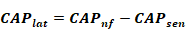
Note: The air leaving the AC unit is limited to 95% relative humidity. If that limit is invoked, CAPlat is reduced and CAPsen is increase.
EERt is calculated as follows:
Equation 226
|
When |
|
|
DBt ≤ 82 ºF |
EERt = SEERnf |
|
82 < DBt < 95 °F |
EERt = SEERnf + ((DBt - 82)*(EERnf – SEERnf) / 13) |
|
DBt ≥ 95 °F |
EERt = EERnf |
Where:
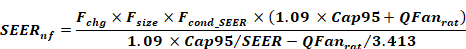
SEERnf = Seasonal energy efficiency ratio at current conditions without distribution fan consumption (“nf” = no fans). This is calculated using Equation 227.
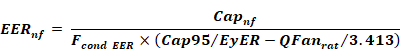
EERnf = Energy efficiency ratio at current conditions without distribution fan consumption (“nf” = no fans) and adjusted for refrigerant charge and airflow. This is calculated using Equation 228.
Equation 227
Fcond_SEER = Fcond_cap / (ASEER × DBec +
BSEER × WBec +
CSEER × DBt +
DSEER × CFMper ton +
ESEER × DBec × DBt +
FSEER × DBec × CFMper ton +
GSEER × WBec × DBt +
HSEER × WBec × CFMper ton +
ISEER × DBt × CFMper ton +
JSEER × WBec2 +
KSEER / CFMper ton +
LSEER)
Coefficients as follows:
|
SHR Condition |
SHR < 1 |
SHR = 1 |
|
ASEER |
0 |
0.0046103 |
|
BSEER |
-0.0202256 |
0 |
|
CSEER |
0.0236703 |
0.0125598 |
|
DSEER |
-0.0006638 |
-0.000512 |
|
ESEER |
0 |
-0.0000357 |
|
FSEER |
0 |
0.0000105 |
|
GSEER |
-0.0001841 |
0 |
|
HSEER |
0.0000214 |
0 |
|
ISEER |
-0.00000812 |
0 |
|
JSEER |
0.0002971 |
0 |
|
KSEER |
-27.95672 |
0 |
|
LSEER |
0.209951063 |
-0.316172311 |
Equation 228
Where:
Fcond_EER = (AEER × DBec +
BEER × WBec +
CEER × DBt +
DEER × CFMper ton +
EEER × DBec × DBt +
FEER × DBec × CFMper ton +
GEER × WBec × DBt +
HEER × WBec × CFMper ton +
IEER × DBt × CFMper ton +
JEER × WBec2 +
KEER / CFMper ton +
LEER)
Coefficients as follows:
|
SHR Condition |
SHR < 1 |
SHR = 1 |
|
AEER |
0 |
0.004610300 |
|
BEER |
-0.020225600 |
0 |
|
CEER |
0.023670300 |
0.012559800 |
|
DEER |
-0.000663800 |
-0.000512000 |
|
EEER |
0 |
-0.000035700 |
|
FEER |
0 |
0.000010500 |
|
GEER |
-0.000184100 |
0 |
|
HEER |
0.000021400 |
0 |
|
IEER |
-0.000008120 |
0 |
|
JEER |
0.000297100 |
0 |
|
KEER |
-27.956720000 |
0 |
|
LEER |
0.015003100 |
-0.475306500 |
The air source heat pump model is based on methods presented in AHRI Standard 210/240-2008.
Primary model parameters. The following values characterize the ASHP and are constant for a given unit:
Cap47 = Rated heating capacity at outdoor dry-bulb temperature = 47 °F
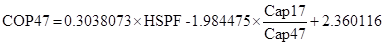
COP47 = Coefficient of performance at outdoor dry bulb = 47 °F (if available, see below)
Cap35 = Heating capacity under frosting conditions at outdoor dry-bulb temperature = 35 °F (if available, see below)
COP35 = Coefficient of performance at outdoor dry bulb = 35 °F (if available, see below)
Cap17 = Rated heating capacity at outdoor dry-bulb temperature = 17 °F
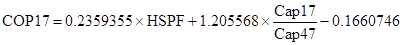
COP17 = Coefficient of performance at outdoor dry bulb = 17 °F (if available, see below)
HSPF = Rated Heating Seasonal Performance Factor, Btuh/Wh
COPbu = COP of backup heating, default = 1 (electric resistance heat)
Capbu = Available backup heating capacity, Btuh
Derived model parameters.
Inp47 = Electrical input power at 47 °F = Cap47 / COP47, Btuh (not W)
Inp17 = Electrical input power at 17 °F = Cap17 / COP17, Btuh (not W)
Estimation of unavailable model parameters.


Simulation
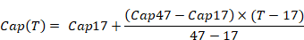
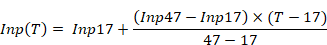
Full-load capacity and input power of the ASHP is determined each time step as a function of outdoor dry-bulb temperature T, as follows --
If (17 °F < T < 45 °F)
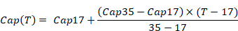
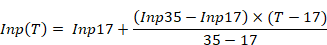
Else
Resistance heat.
Load in excess of Cap(T) is met with backup heating at COPbu.
CSE determines the capacity of HVAC equipment via an auto-sizing capability. Autosizing is conducted prior to the main annual simulation. It is done by using the hourly simulator for a set of design days and increasing capacity as needed to maintain thermostat set points. Each design day is repeated several times until the required capacity converges. The set of design days includes one cold day with no solar gain and several hot days at with clear-sky solar at different times of the year. This ensures that maximums of both heating and cooling loads will be found. Equipment characteristics other than capacity are specified on a per-unit basis (e.g. “cfm per ton”), so a full description of the system can be derived from the primary capacity.
The sizing procedure uses the equipment models in an inverse mode. For example, the sensible cooling load for a given set up conditions is back-converted to the required rated total capacity (Cap95) by using inverted forms of the model equations. The general simulation calculation sequence is used, but the logic of the HVAC models is altered during the autosizing phase.
Note that for air-source heat pumps, only the backup heating capacity is autosized. In addition, modeled duct sizes are not sized and must be specified.
The equipment sizes calculated by CSE are used for compliance analysis only and are not substitutes for load calculations used for selecting equipment or meeting other code requirements.