 = insolation
incident on window system.
= insolation
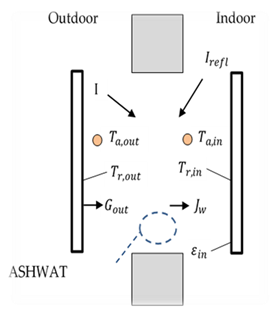
incident on window system.The ASHWAT algorithm is used to model complex windows with diatherminous layers and curtains, etc. (Wright and Kotey 2006, Wright, J.L. 2008). Given the environmental conditions on each side of the window, ASHWAT determines the long wave, short wave and convection heat transfers to the conditioned space.
For the following input and output discussion, ASHWAT is treated as a black box.
Each time step, for each window, ASHWAT is given the environmental inputs:
= insolation
incident on window system.
Irefl= insolation reflected diffusely from the other room surfaces.
Ta,out = outside dry bulb air temperature.
Ta,in = inside dry bulb air temperature.
Tr,in = the temperature of the indoor plate.
Tr,out = the temperature of the outdoor plate.
Figure 13: ASHWAT Inputs and Nomenclature
ASHWAT’s output gives heat transfer rates and circuit elements of Figure 14. The circuit of Figure 14 is part of the conditioned zone radiant network of Figure 2 and Figure 3 (with some different nomenclature).
Figure 14: Window System Representation in CSE
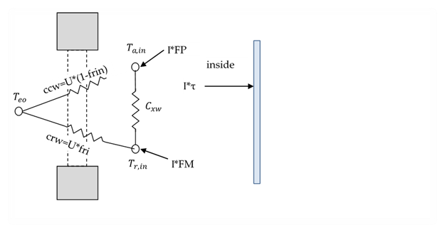
In Figure 14,
FP=fraction of the heat from Insolation absorbed in the various window layers that ends up being transferred to the inside radiant node.
FM=fraction of the heat from Insolation absorbed in the various window layers that ends up being convected to the inside air node.
frin = fraction of total non-solar heat transfer that goes to the inside radiant node; dimensionless.
frout= fraction of non-solar heat transfer to the outside that goes to the outside radiant node.
U = conductance between the inside and outside effective temperatures, Tei and Teo; Btu/(hr-sf-F) where
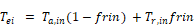

the effective outdoor temperature; F.
Cxw= the cross coupling term; Btu/(hr-sf-F).
τ = the short wave transmissivity of the window system.
Note that the solar heat gain coefficient is: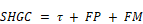
Net energy into zone via window, per unit COG area = + I(


ASHWAT models the irradiation on the outside of the window system as if it were
emitted by a black plate parallel to the window at temperature

Equation 118
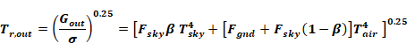
where Gout has been replaced by Equation 67.
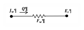
From Figure 13, the equivalent network between the radiosity of the window system, Jw and the inside plate is shown in Figure 15. The circuit parameters are in the conductance form. The “1” is the view factor between the plate and the window.
Figure15: Equivalent Network between the Radiosity of the Window System, J_w, and the Inside Plate
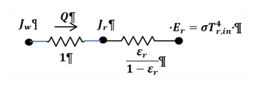
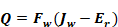
Figure 15 reduces to:
Figure 16: Reduced Figure 15
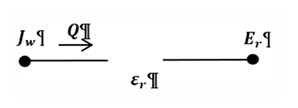
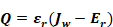
Thus the heat transfer rate per unit area, with Q positive from window to room, is:
Equation 119
From Figure 9 the network between the radiosity of a surface and the mean radiant temperature node is shown in Figure 17. This corresponds to Figure 16 for the ASHWAT algorithm:
Figure 17: Network between the Radiosity of a Surface and the Mean Radiant Temperature Node
with the corresponding heat transfer rate:
Equation 120
Comparing Equation 119 and Equation 120 shows that to obtain the heat flow consistent with the Carroll network ASHWAT must model the window by setting inside plate’s emissivity to the value of Fw
Equation 121

Fw is the Carroll MRT view factor defined in Section 2.6.1. Fw is slightly larger than 1, and serves to increase the heat transfer between Jw and Er to compensate for the fact that |Jw Er| is smaller than it would if Tr,in had not included the window temperature in its average. This MRT view factor effect cannot be simulated by a parallel plate model without the trick of artificially raising the emissivity of the inside plate to the value Fw.