This section summarizes the procedures for verifying refrigerant charge for air-conditioning systems as described in Section RA3.2 of the Reference Residential Appendix.
4.8.1.1 Overview
A split-system air conditioner undergoes the final assembly at installation. The installation must be verified to ensure proper performance. Important factors that affect performance include the amount of refrigerant in the system (the charge) and the proper functioning of the metering device. Air conditioner energy efficiency suffers if the refrigerant charge is either too low or too high and if the metering device (TXV or EXV) is not functioning properly. In addition to a loss of efficiency and capacity, errors in these areas can lead to premature compressor failure.
To help avoid these problems, the prescriptive standards require that systems be correctly installed. The prescriptive standards also require that they be field-verified in Climate Zones 2 and 8 through 15. Refrigerant charge verification is also required in any climate zone when chosen as a compliance feature using the performance approach.
The requirement to verify the refrigerant charge after installation does not apply to new packaged systems, where the installer certifies the package system came factory-charged and did not alter the system in any way that would affect the refrigerant level; however, airflow and other requirements must still be verified. The prescriptive standards regarding verification of refrigerant charge do apply to altered package systems in Climate Zones 2 and 8 through 15.
Verification of proper refrigerant charge must occur after the HVAC contractor has installed and charged the system in accordance with the manufacturer’s specifications. The procedure requires properly calibrated digital refrigerant gauges, thermocouples, and digital thermometers. When multiple systems in the same home require testing, test each system.
In a typical home cooling system, there are two important performance criteria that are relatively easy to verify that there is neither too much nor too little refrigerant in the system. In systems with a fixed-orifice device in the evaporator coil, the number to check is called the superheat. In a system with a variable-metering device, the number to check is called the subcooling.
Superheat refers to the number of degrees the refrigerant is raised after it evaporates into a gas. This occurs inside the evaporator coil (or indoor coil). The correct superheat for a system will vary depending on certain operating conditions. The target superheat for a system must be obtained from a table provided in the RA3.2 protocols or the manufacturer’s superheat table. There is an allowed range of several degrees between the measured superheat and the target superheat for a system to pass.
Subcooling refers to the number of degrees the refrigerant is lowered after it condenses into a liquid. This occurs inside the condenser coil (or outdoor coil). The manufacturer specifies the correct subcooling for a system. It may vary depending on operating conditions. Like superheat, there is an allowed range of several degrees between the measured subcooling and the target subcooling for a system to pass.
The temperature at which a refrigerant condenses or evaporates is called the saturation temperature. Above the saturation temperature, a refrigerant is always a gas. Below the saturation temperature, a refrigerant is always a liquid.
Saturation is when a refrigerant exists as both a liquid and a gas. It always occurs at the same temperature, depending on what the pressure of the refrigerant happens to be. At higher pressures, the saturation temperature goes up and vice versa. This convenient property is what makes refrigeration work.
The saturation temperature can be determined by simply measuring the pressure of a refrigerant and referring to a table, known as a pressure-temperature (PT) table, for that specific refrigerant. Saturation temperatures are well-documented for all common refrigerants.
Because variable refrigerant metering devices are prone to failure and even more so to improper installation, it is important that the operation of these devices be checked. A metering device maintains a relatively constant superheat over a wide range of operating conditions; therefore, checking the superheat, in addition to the other tests performed, will indicate if the metering device is operating correctly.
Unfortunately, checking superheat and subcooling can be done only under certain indoor and outdoor conditions. This verification procedure, called the Standard Charge Verification Method, is very weather-dependent.
There is another way to verify proper refrigerant charge that is not weather–dependent, and that is by weighing the refrigerant. Called the Weigh-in Charge Verification Method, this approach can be performed only by the installer. It can be verified by the HERS Rater either by simultaneous observation or by using the standard method when conditions permit.
4.8.1.2 Minimum System Airflow Verification for Refrigerant Charge Verification
To have a valid charge test, the system airflow must be verified to be at least 300 CFM/ton for altered systems and 350 CFM/ton for new systems. The procedures for measuring total system airflow are found in RA3.3. They include plenum pressure matching using a fan flow meter, a flow grid, a powered flow hood, and the traditional (nonpowered) flow hood. The airflow verification procedures for refrigerant charge verification no longer include the temperature split method.
If an altered system does not meet the minimum airflow requirements, remedial steps are required to increase system airflow. More airflow is generally better for systems with air conditioning. Not only does this allow proper refrigerant charge to be verified, but it improves the overall performance of the system. When able to be performed on a system, regardless of the refrigerant charge verification procedure, minimum system airflow must always be verified.
In some alterations, improving airflow may be cost-prohibitive, and there is a process for documenting this (RA3.3.3.1.5). When this option is used, verification by sample groups is not allowed. Minimum airflow is critical to proper air-conditioner operation. Reducing airflow reduces cooling capacity and efficiency. Many systems in California have oversized equipment and undersized ducts. In newly installed duct systems, the minimum airflow requirement is higher because the opportunity exists to design and install a better system. In altered systems, the installer may be required to modify the ducts system to meet the minimum airflow. The minimums of 300 and 350 CFM/ton are lower than the desired airflow for most systems, which is usually 400 CFM/ton and higher.
4.8.1.3 Standard Charge Verification Procedure (RA3.2.2)
The first step is to turn on the air-conditioning system and let it run for at least 15 minutes to stabilize temperatures and pressures. While the system is stabilizing, the HERS Rater or the installer may attach the instruments needed to take the measurements.
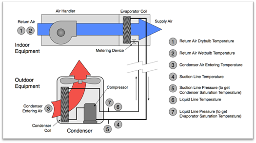
Figure 4-45: Measurements for Refrigerant Charge and Airflow Tests
Source: California Energy Commission
The following measurements shall be taken by the technician or HERS Rater, when applicable.
1. The return air wet bulb and dry bulb temperatures are measured in the return plenum before the blower at the location labeled "Title 24 – Return Plenum Measurement Access Hole." This hole must be provided by the installer, not the rater (See Points 1 and 2 in Figure 4-45. See Figure RA 3.2-1 for more information on the placement of the measurement access hole (MAH).
2. Moreover, the outdoor air dry bulb temperature is measured at the point where the air enters the outdoor condensing coil. (See Point 3 in Figure 4-45). It is important that this outdoor temperature sensor be shaded from direct sun during the verification procedure.
In addition to the air temperature measurements, four refrigerant properties need to be measured. Two of these measurements are taken near the suction line service valve before the line enters the outdoor unit and are used to check the superheat.
1. The first measurement is the temperature of the refrigerant in the suction line, which is taken by a clamp-on thermocouple or other suitable device insulated from the outdoor air. (See Point 4 in Figure 4-45.)
2. The second measurement determines the saturation temperature of the refrigerant in the evaporator coil. (See Point 5 in Figure 4-45.)The saturation temperature can be determined from the low-side (suction line) pressure and a saturation temperature table for the applicable refrigerant.
To check the subcooling, two more refrigerant properties are required and may be measured near the liquid line service valve at the point where the line exits the outdoor unit.:
1. The liquid refrigerant temperature in the liquid line is measured by a clamp-on thermocouple insulated from the outdoor air. (See Point 6 in Figure 4-45.)
2. The condenser saturation temperature can be determined from the liquid line pressure and a saturation temperature table for the applicable refrigerant. (See Point 7 in Figure 4-45.)
Determination of the condenser saturation temperature and the liquid line temperature is used only for the subcooling verification method on systems with TXV or EXV metering devices.
4.8.1.4 Superheat Charge Verification Method (RA3.2.2.6.1)
The Superheat Charge Verification Method is used on units with a fixed refrigerant metering device (not a TXV or EXV).
Airflow verification must be confirmed before starting the Superheat Verification Method.
|
|
|
Return Air Wet-Bulb Temperature (°F) (T Return, wb) | |||||||||
|
|
50 |
51 |
52 |
53 |
54 |
55 |
-- |
-- |
75 |
76 | |
|
Condenser Air Dry-Bulb Temperature (°F) (T condenser, db) |
55 |
Target Superheat = Suction Line Temperature minus Evaporator Saturation Temperature See Reference Residential Appendix Table RA3.2-2 | |||||||||
|
56 | |||||||||||
|
57 | |||||||||||
|
-- | |||||||||||
|
-- | |||||||||||
|
93 | |||||||||||
|
94 | |||||||||||
|
95 | |||||||||||
Source: California Energy Commission
The Superheat Verification Method compares the actual (measured) superheat temperature to a target value from a table. The actual superheat temperature is the measured suction line temperature (TSuction, db) minus the evaporator saturation temperature (TEvaporator, Saturation). The target superheat value is read from a table (Table RA3.2-2 of the Reference Residential Appendix or the manufacturer’s superheat table).
For illustration, the structure of Table RA3.2-2 is shown above as Table 4-20.
Only an EPA-certified technician may add or remove refrigerant. Under no circumstances may HERS Raters add or remove refrigerant on systems that they are verifying.
4.8.1.5 Subcooling Verification Method (RA3.2.2.6.2)
The Subcooling Verification Method is used on units with a variable refrigerant metering device (a TXV or EXV).
Airflow verification must be confirmed before starting the Subcooling Verification Method.
The Subcooling Verification Method compares the actual subcooling temperature to the target value supplied by the manufacturer. The actual subcooling is the condenser saturation temperature (TCondenser, Saturation) minus the liquid line temperature (TLiquid).
4.8.1.6 Weigh-In Charging Procedure (RA3.2.3)
The weigh-in charging procedure charges the system by determining the appropriate weight of refrigerant based on the size of the equipment and refrigerant lines rather than by measuring steady-state performance of the system. Systems using the weigh-in procedure to meet the refrigerant charge verification requirement may not use group sampling procedures for HERS verification compliance.
The weigh-in procedure does not relieve the installer of the responsibility to comply with the required minimum system airflow.
There are two installer options for completing the weigh-in procedure. One involves adjusting the amount of refrigerant supplied by the manufacturer in a new system,as specified by the manufacturer (weigh-in charge adjustment). The other involves evacuating the entire system and recharging it with the correct total amount of refrigerant, by weight (weigh-in total charge).
The weigh-in charge adjustment procedure may be used only when a new factory-charged outdoor unit is being installed and the manufacturer provides adjustment specifications based on evaporator coil size and refrigerant line size and length.
The weigh-in total charge may be used for any weigh-in procedure but still requires manufacturer’s adjustment specifications. Only the installer/technician may perform any kind of weigh-in procedure.
4.8.1.7 Equipment Limitations
The Energy Standards specifically require verification of refrigerant charge only for air-cooled air conditioners and air-source heat pumps. All other types of systems are not expressly exempt from the refrigerant charge requirements. Certain portions of the requirements may still apply, such as the minimum system airflow requirement. The installer would have to verify with the manufacturer and confirm with the Energy Commission. The installer must adhere strictly to the manufacturer’s specifications.
Variable refrigerant flow systems and systems such as some mini-split systems that cannot be verified using the standard charge verification procedure in RA3.2.2 must demonstrate compliance using the weigh-in method. Verification by the HERS Rater can be accomplished only by simultaneous observation of the installer’s weigh-in as specified by RA3.2.3.2, and only if use of HERS Rater observation procedure is specified by the Standards.
4.8.1.8 HERS Verification Procedures
When required by the certificate of compliance, HERS Raters must perform field verification and diagnostic testing of the refrigerant charge, including verification of minimum system airflow and verification of installation of the measurement access hole.
The verification procedures are essentially identical for the rater and the installer except that the tolerances for passing the superheat and subcooling tests are less stringent for the rater’s test. This is to allow for some variations in measurements due to instrumentation or test conditions (for example, weather).
The following conditions prohibit verification using sample groups:
1. When the weigh-in method is used
2. When the minimum airflow cannot be met despite reasonable remediation attempts. (See RA3.3.3.1.5).
As always, to be eligible for sampling, the installer must first verify and pass the system. If sampling is not being used, the rater will perform the verification only after the installer has charged the system according to manufacturer’s specifications.
4.8.1.9 Winter Setup Procedures
Reference Appendix RA1 provides for the approval of special case refrigerant charge verification procedures. These protocols may be used only if the manufacturer has approved use of the procedure for their equipment.
One such procedure is found in RA1.2 Winter Setup for the standard charge verification procedure (winter charge setup). It provides for a modification to the standard charge procedure when temperature conditions do not allow use of the RA3.2.2 standard charge verification procedure.
The winter charge setup allows both installers and HERS Raters to verify the charge when outdoor temperatures are below the manufacturer's allowed temperature, or the outdoor temperature is less than 55°F. The Weigh-in Charging Procedure specified in Section RA3.2.3 may also be used when the outdoor temperatures are below the manufacturer's allowed temperature or below 55°F, but may be used only by the installer.
The winter charge setup procedure allows the system to operate in the same range of pressure differences between the low-side pressure and the high-side pressure as occurs during warm outdoor temperatures, by restricting the airflow at the condenser fan outlet. The winter charge setup is used only for units equipped with variable metering devices, which include thermostatic expansion valves (TXV) and electronic expansion valves (EXV) for which the manufacturer specifies subcooling as the means for determining the proper charge for the unit, including units equipped with microchannel heat exchangers. Once this pressure differential is achieved, the variable metering device calculations are conducted in the same way as the variable metering device procedures described in Reference Residential Appendix RA 3.2.2.6.2. All other applicable requirements of Section RA3.2.2 remain the same and must be completed when using the winter charge setup.
Though not specifically mentioned in the FID protocols in Residential Appendix RA3.4.2, the RA1.2 winter setup method may be used if applicable. Thus for FID verification, the winter setup method may be used in place of the subcooling method.
4.8.1.10 Using Weigh-In Charging Procedure at Low Outdoor Temperatures
When a new HVAC system is installed, the HVAC installer must check the refrigerant charge, and a HERS Rater must verify the correct charge; however, an exception to §150.1(c)7A provides for an alternative third-party HERS verification if the weigh-in method is used when the outdoor temperature is less than 55 degrees F.
Typically, when the weigh-in method is used by the installing contractor, a HERS Rater must perform a charge verification in accordance with the RA3.2. standard charge procedure. However, because the RA3.2.2 procedures cannot be used when the outdoor temperatures are less than 55 degrees, the Energy Standards provide the installer with two choices:
1. Use the RA3.2.3.2 HERS Rater Observation of Weigh-In Charging Procedure to demonstrate compliance, and install an occupant-controlled smart thermostat (OCST).
2. Wait for warmer temperatures and perform the standard charge verification procedure. In this case, the installer must agree to return to correct refrigerant charge if a HERS Rater determines later, when the outside temperature is 55 degrees F or above, that correction is necessary as described in Residential Appendix RA 2.4.4. The installer must also provide written notice to the homeowner that the charge has not yet been verified. An example homeowner’s notification is shown in Figure 4-46.
Figure 4-46: Example of Notification to Homeowners of Delayed Charged Verification
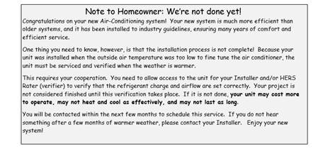
Source: California Energy Commission