This derivation is for one zone only, and the nomenclature is specific to this appendix alone.
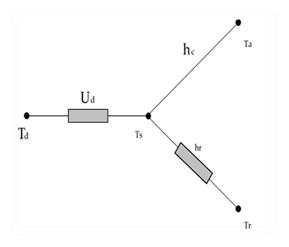
Heat transfer through the duct walls can be illustrated in the electrical analogy in Figure A-1. The first node on the left represents the temperature of the air in the duct (Td) and is connected to the temperate on the surface of the duct (Ts) by the conductance through the duct wall (Ud). The convective heat transfer coefficient (hc) connects the surface temperature to the duct zone air temperature (Ta). The radiation heat transfer coefficient (hr) connects the surface temperature to the duct zone radiant temperature (Tr).
Figure A-1: Electrical Analogy of Heat Transfer through a Duct Wall
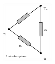
The temperatures of the duct zone are assumed to be constant; the duct surface temperature is not. The duct surface temperature can be removed from the analysis by using a Y-Δ transform. Figure A-2 shows the result of this transformation with direct connections between the duct air temperature, the duct zone radiant and air temperatures through combined coefficients defined in Equation A-1.


where
Figure A-2: Heat Transfer through a Duct Wall with Surface Temperature Removed
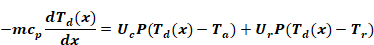
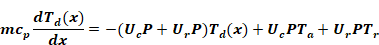
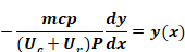
Using an energy balance, the rate of change of heat flow
along the length ( ) of duct must equal the heat flow
through the duct wall, or
) of duct must equal the heat flow
through the duct wall, or
Equation A-2
where
 = capacitance flow rate of the
air in the duct
= capacitance flow rate of the
air in the duct
 =
temperature of air in the duct
=
temperature of air in the duct
 = equivalent heat
transfer coefficient (see Equation A-1)
= equivalent heat
transfer coefficient (see Equation A-1)
 =
perimeter of duct
=
perimeter of duct
 =
temperature of air in duct zone
=
temperature of air in duct zone
 = equivalent heat
transfer coefficient (see Equation A-1
= equivalent heat
transfer coefficient (see Equation A-1
 = radiant
temperature in duct zone
= radiant
temperature in duct zone
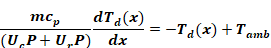
Regrouping by temperature terms
Equation A-3
and dividing through by the quantity (Uc P+Ur P) gives
Equation A-4
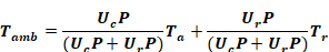
Where
Equation A-5
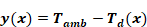
Let  be
be
Equation A-6
The derivative of which is
Equation A-7

Substituting Equation A-6 and Equation A-7 into Equation A-4 gives
Equation A-8
Rearranging
Equation A-9
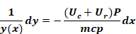
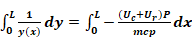
and integrating from entrance ( ) to exit (
 )
)
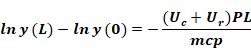
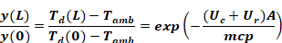
Equation A-10
Equation A-11
Recalling the definition in
Equation A-6 and replacing the product of the perimeter and length with the
surface area ( ) of the duct, and a bit of
manipulation yields the following relationships
) of the duct, and a bit of
manipulation yields the following relationships
Equation A-12
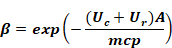
Let
Equation A-13
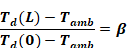
Then
Equation A-14
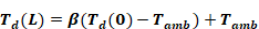
Solving for the exit temperature gives
Equation A-15
The temperature change in length L of duct is
Equation A-16

This can be rewritten as
Equation A-17
Let  be the sensible heat exchanger
effectiveness
be the sensible heat exchanger
effectiveness
Equation A-18

Then the conduction loss from the duct to the duct zone can then be written as
Equation A-19
