
This section is applicable to the DHW system type 3 and 4, as defined in B1. The distribution losses accounted for in the distribution loss multiplier (DLM), Equation 5, reflect distribution heat loss within each individual dwelling unit. Additional distribution losses occur outside dwelling units and they include losses from recirculation loop pipes and branch piping feeding individual dwelling units. The hourly values of these losses, HRDL, shall be calculated according to Equation 18. Compliance software shall provide input for specifying recirculation system designs and controls according to the following algorithms
Equation 15
where
HRDLk= Hourly central system distribution loss for kth system (Btu).
HRLLk=
Hourly
recirculation loop pipe heat loss (Btu). This component is only applicable to
system type 4, see Equation 16
HRBLk=
Hourly
recirculation branch pipe heat loss (Btu), see Equation 24
NLoopk= Number of recirculation loops in water heating system k; this component is only applicable to system type 4, see Section 4.3
A recirculation loop usually includes multiple pipe sections, not necessarily having the same diameter, that are exposed to different ambient conditions. The compliance software shall provide input entries for up to six pipe sections with three sections for supply piping and three sections for return piping for users to describe the configurations of the recirculation loop. For each of the six pipe sections, input entries shall include pipe diameter (inch), pipe length (ft), and ambient conditions. Ambient condition input shall include three options: outside air, underground, conditioned or semi-conditioned air. Modeling rules for dealing with recirculation loop designs are provided in Section 4.3.
Outside air includes crawl spaces, unconditioned garages, unconditioned equipment rooms, as well as actual outside air. Solar radiation gains are not included in the calculation because the impact of radiation gains is relatively minimal compared to other effects. Additionally, the differences in solar gains for the various conditions (e.g., extra insulation vs. minimum insulation) are even less significant.
The ground condition includes any portion of the distribution piping that is underground, including that in or under a slab. Insulation in contact with the ground must meet all the requirements of Section 150.0(j), Part 6, of Title 24.
The losses to conditioned or semi-conditioned air include losses from any distribution system piping that is in an attic space, within walls (interior, exterior or between conditioned and unconditioned spaces), within chases on the interior of the building, or within horizontal spaces between or above conditioned spaces. It does not include the pipes within the residence. The distribution piping stops at the point where it first meets the boundaries of the dwelling unit.
Hourly recirculation loop pipe heat loss (HRLLk) is the hourly heat loss from all six pipe sections. There are two pipe heat loss modes, pipe heat loss with non-zero water flow (PLWF) and pipe heat loss without hot water flow (PLCD). The latter happens when the recirculation pump is turned off by a control system and there are no hot water draw flows, such as in recirculation return pipes.
Compliance software shall provide four options of recirculation system controls listed in Table B-2 . A proposed design shall select a control type from one of the four options. The standard design shall use demand control.
Table B-2. Recirculation Loop Supply Temperature and Pump Operation Schedule
|
Hour |
No Control |
Demand Control |
Temperature Modulation |
Temperature Modulation with Continuous Monitoring | ||||
|
Tin,1 (oF) |
SCHk,m |
Tin,1 (oF) |
SCHk,m |
Tin,1 (oF) |
SCHk,m |
Tin,1 (oF) |
SCHk,m | |
|
1 |
130 |
1 |
130 |
0.2 |
120 |
1 |
115 |
1 |
|
2 |
130 |
1 |
130 |
0.2 |
120 |
1 |
115 |
1 |
|
3 |
130 |
1 |
130 |
0.2 |
120 |
1 |
115 |
1 |
|
4 |
130 |
1 |
130 |
0.2 |
120 |
1 |
115 |
1 |
|
5 |
130 |
1 |
130 |
0.2 |
120 |
1 |
115 |
1 |
|
6 |
130 |
1 |
130 |
0.2 |
125 |
1 |
120 |
1 |
|
7 |
130 |
1 |
130 |
0.2 |
130 |
1 |
125 |
1 |
|
8 |
130 |
1 |
130 |
0.2 |
130 |
1 |
125 |
1 |
|
9 |
130 |
1 |
130 |
0.2 |
130 |
1 |
125 |
1 |
|
10 |
130 |
1 |
130 |
0.2 |
130 |
1 |
125 |
1 |
|
11 |
130 |
1 |
130 |
0.2 |
130 |
1 |
125 |
1 |
|
12 |
130 |
1 |
130 |
0.2 |
130 |
1 |
125 |
1 |
|
13 |
130 |
1 |
130 |
0.2 |
130 |
1 |
125 |
1 |
|
14 |
130 |
1 |
130 |
0.2 |
130 |
1 |
125 |
1 |
|
15 |
130 |
1 |
130 |
0.2 |
130 |
1 |
125 |
1 |
|
16 |
130 |
1 |
130 |
0.2 |
130 |
1 |
125 |
1 |
|
17 |
130 |
1 |
130 |
0.2 |
130 |
1 |
125 |
1 |
|
18 |
130 |
1 |
130 |
0.2 |
130 |
1 |
125 |
1 |
|
19 |
130 |
1 |
130 |
0.2 |
130 |
1 |
125 |
1 |
|
20 |
130 |
1 |
130 |
0.2 |
130 |
1 |
125 |
1 |
|
21 |
130 |
1 |
130 |
0.2 |
130 |
1 |
125 |
1 |
|
22 |
130 |
1 |
130 |
0.2 |
130 |
1 |
125 |
1 |
|
23 |
130 |
1 |
130 |
0.2 |
130 |
1 |
125 |
1 |
|
24 |
130 |
1 |
130 |
0.2 |
125 |
1 |
120 |
1 |
Pipe heat loss modes are determined by recirculation control schedules and hot water draw schedules. For each pipe section, hourly pipe heat loss is the sum of heat loss from the two heat loss modes.
Hourly heat loss for the whole recirculation loop (HRLLk) is the heat loss from all six pipe sections, according to the following equation:
Equation 16
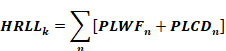
where
PLWFn= Hourly pipe heat loss with non-zero water flow (Btu/hr), see Equation 17
PLCDn= Hourly pipe heat loss without water flow (Btu/hr), see Equation 22
n= Recirculation pipe section index, 1 through 6
Equation 17

where
Flown = Flowrecirc + Flown,draw (gph), assuming
Flown,draw = Average hourly hot water draw flow (gph); for supply sections, n=1, 2, or 3, Flown,draw = GPHk/NLoopk; for return pipes, n=4, 5, and 6, Flown,draw = 0
Flowrecirc = Hourly recirculation flow (gph) is assumed to be 360 gallons based on the assumption that the recirculation flow rate is 6 gpm
fnoflow,n = Fraction of the hour for pipe section n to have zero water flow, see Equation 18
ρ = Density of water, 8.345 (lb/gal)
Cp = Specific heat of water, 1 (Btu/lb-oF)
Tn,in = Input temperature of section n (oF); for the first section (n=1), T1,in shall be determined based on Table B-2 . The control schedule of the proposed design shall be based on user input. The standard design is demand control. For other sections, input temperature is the same as the output temperature the proceeding pipe section, Tn,in = Tn-1,out
Tn,out = Output temperature of section n (oF), see Equation 19.
Equation 18
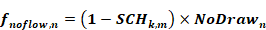
where
NoDrawn = Fraction of the hour that is assumed to have no hot water draw flow for pipe section n; NoDraw1 = 0.2, NoDraw2 = 0.4, NoDraw3 = 0.6, NoDraw4 = NoDraw5 = NoDraw6 = 1
SCHk,m = Recirculation pump operation schedule, representing the fraction of the hour that the recirculation pump is turned off, see Table B-2. SCHk,m for the proposed design shall be based on proposed recirculation system controls. Recirculation system control for the standard design is demand control.
Equation 19
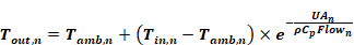
where
TAmb,n = Ambient temperature of section n (oF), which can be outside air, underground, conditioned, or semi-conditioned air. Outside air temperatures shall be the dry-bulb temperature from the weather file. Underground temperatures shall be obtained from Equation 11. Hourly conditioned air temperatures shall be the same as conditioned space temperature. For the proposed design, Tamb,n options shall be based on user input. The standard design assumes all pipes are in conditioned air.
UAn = Heat loss rate of section n (Btu/hr-°F), see Equation 20
Equation 20
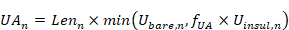
where
Lenn = Section n pipe length (ft); for the proposed design, use user input; for the standard design, see Equation 31
Ubare,n, Uinsul,n = Loss rates for bare (uninsulated) and insulated pipe (Btu/hr-ft-oF), evaluated using Equation 21 with section-specific values, as follows:
Dian = Section n pipe nominal diameter (inch); for the proposed design, use user input; for the standard design, see Equation 32
Thickn = Pipe insulation minimum thickness (inch) as defined in the Title 24 Section 120.3, TABLE 120.3-A for service hot water system
Condn = Insulation conductivity shall be assumed = 0.26 (Btu inch/h∙sf∙F)
hn = Section n combined convective/radiant surface coefficient (Btu/hr-ft2-F) assumed = 1.5
fUA = Correction factor to reflect imperfect insulation, insulation material degradation over time, and additional heat transfer through connected branch pipes that is not reflected in branch loss calculation. It is assumed to be 2.0.
Equation 21 defines general relationships used to calculate heat loss rates for both loop and branches using appropriate parameters.
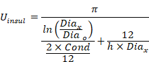
Equation 21

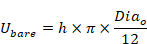

where
Dia = Pipe nominal size (in)
Diao = Pipe outside diameter (in)
Diax = Pipe + insulation outside diameter (in)
Thick = Pipe insulation thickness (in)
Cond = Insulation conductivity (Btu in/hr-ft2- oF)
h = Combined convective/radiant surface coefficient (Btu/hr-ft2- oF)
Pipe heat loss without water flow shall be calculated according to the following equations:
Equation 22

where
Voln
= Volume of section n (gal) is calculated as
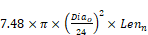
where 7.48 is the volumetric unit conversion factor from cubic feet to gallons. Note that the volume of the pipe wall is included to approximate the heat capacity of the pipe material.
Tn,start = Average pipe temperature (oF) of pipe section n at the beginning of the hour. It is the average of Tn,in and Tn,out calculated according to Equation 19 and associated procedures.
Tn,end = Average pipe temperature (oF) of pipe section n at the end of pipe cool down, see Equation 23
Equation 23
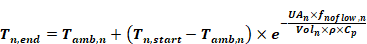
Equation 23 calculates average pipe temperature after cooling down, so the pipe heat loss calculated by Equation 22 is for pipe with zero flow for fraction fnoflow,n of an hour. Recirculation pumps are usually turned off for less than an hour and there could be hot water draw flows in the pipe. As a result, recirculation pipes usually cool down for less than an hour. The factor fnoflow, n calculated according Equation 18 is used to reflect this effect in Equation 23.
The proposed design and standard design shall use the same branch pipe heat loss assumptions. Branch pipe heat loss is made up of two components. First, pipe heat losses occur when hot water is in use (HBUL). Second, there could be losses associated with hot water waste (HBWL) when hot water was used to displace cold water in branch pipes and hot water is left in pipe to cool down after hot water draws and must be dumped down the drain.
The Total Hourly Branch Losses (HRBLk) shall include both components and be calculated as:
Equation 24

where
HBUL = Hourly pipe loss for one branch when water is in use (Btu/hr), see Equation 25
HBWL = Hourly pipe loss for one branch due to hot water waste (Btu/hr), see Equation 28
Nbranchk = Number of branches in water heating system k, see Equation 33
The hourly branch pipe loss while water is flowing is calculated in the same way as recirculation pipe heat loss with non-zero water flow (PLWF) using the following equations:
Equation 25
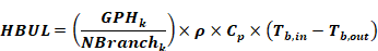
where
Tb,in = Average branch input temperature (oF). It is assumed to be equal to the output temperature of the first recirculation loop section, T1,out
Tb,out = Average branch output temperature (oF), see Equation 26
Equation 26
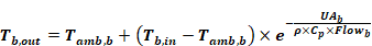
where
Tamb,b = Branch pipe ambient temperature (°F) Branch pipes are assumed to be located in the conditioned or semi-conditioned air.
UAb = Branch pipe heat loss rate (Btu/hr-°F), see Equation 27
Flowb = Branch hot water flow rate during use (gal/hr). It is assumed to be 2 gpm or 120 gal/hr.
The branch pipe heat loss rate is
Equation 27

where
Lenb = Branch pipe length (ft), see Equation 35
Uinsul,b = Loss rate for insulated pipe (Btu/hr-ft-oF), evaluated using Equation 21 with branch-specific values, as follows:
Diab = Branch pipe diameter (inch), see Equation 34
Thickb = Branch pipe insulation minimum thickness (inch) as defined in the Title 24 Section 120.3, TABLE 120.3-A for service hot water system.
Condb = Branch insulation conductivity, assumed = 0.26 Btu in/hr-ft2- oF
hb= Branch combined convective/radiant surface coefficient (Btu/hr-ft2- oF) assumed = 1.5.
The hourly pipe loss for one branch due to hot water waste is calculated as follows:
Equation 28
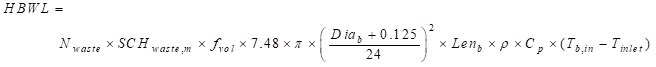
where
Nwaste = Number of times in a day for which water is dumped before use. This depends on the number of dwelling units served by a branch. Statistically, the number of times of hot water waste is wasted is inversely proportional to the number of units a branch serves, see Equation 29 .
SCHwaste,m = Hourly schedule of water waste, see Table B-3
fvol = The volume of hot water waste is more than just the volume of branch pipes, due to branch pipe heating, imperfect mixing, and user behaviors. This multiplier is applied to include these effects and is assumed to be 1.4.
Tin,b = Average branch input temperature (oF) is assumed to equal the output temperature of the first recirculation loop section, TOUT,1
Tinlet = The cold water inlet temperature (ºF) according to Section 3.3 Cold Water Inlet Temperature
Equation 29 Method WH-BRWF
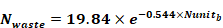
where
Nunitb= Number of dwelling units served by the branch, calculated using Equation 30 (note that Nunitb is not necessarily integral).
Equation 30

|
SCHwaste,m | |
|
1 |
0.01 |
|
2 |
0.02 |
|
3 |
0.05 |
|
4 |
0.22 |
|
5 |
0.25 |
|
6 |
0.22 |
|
7 |
0.06 |
|
8 |
0.01 |
|
9 |
0.01 |
|
10 |
0.01 |
|
11 |
0.01 |
|
12 |
0.01 |
|
13 |
0.01 |
|
14 |
0.01 |
|
15 |
0.01 |
|
16 |
0.01 |
|
17 |
0.01 |
|
18 |
0.01 |
|
19 |
0.01 |
|
20 |
0.01 |
|
21 |
0.01 |
|
22 |
0.01 |
|
23 |
0.01 |
|
24 |
0.01 |
A recirculation system can have one or multiple recirculation loops. Each recirculation loop consists of many pipe sections, which are connected in sequence to form a loop. Each pipe section could have different pipe diameter, length, and location. The compliance software shall use six pipe sections, with three supply pipe sections and three return pipe sections, to represent a recirculation loop. When multiple recirculation loops exist, all recirculation loops are assumed to be identical. The compliance software shall provide default and standard recirculation system designs based on building geometry according to the procedures described in the following sections. The default design reflects typical recirculation loop design practices. The standards design is based on one or two loops and is used to set recirculation loop heat loss budget.
The first step of establishing recirculation system designs is to determine the number of recirculation loops, Nloopk, in water heating system k. The standard design has one recirculation loop, Nloopk =1, when Nunit <= 8, or two recirculation loops, Nloopk =2 for buildings with Nunit > 8. The proposed design is allowed to specify more than one loop only if the design is verified by a HERS rater. Otherwise, the proposed design can only be specified to have one recirculation loop.
The standard and default recirculation loop designs are based on characteristics of the proposed building. There could be many possibilities of building shapes and dwelling unit configurations, which would determine recirculation loop pipe routings. Without requiring users to provide detailed dwelling unit configuration information, the compliance software shall assume the proposed buildings to have same dwelling units on each floor and each floor to have a corridor with dwelling units on both sides. Recirculation loops start from the mechanical room (located on the top floor), go vertically down to the middle floor, loop horizontally in the corridor ceiling to reach the dwelling units on both ends of the building, then go vertically up back to the mechanical room. At each dwelling unit on the middle floor, vertical branch pipes, connected to the recirculation loop supply pipe, are used to provide hot water connection to dwelling units on other floors above and below.
Both the standard and default recirculation loop designs are assumed to have equal length of supply sections and return sections. The first section is from the mechanical room to the middle floor. The second section serves first half branches connected to the loop and the third section serves the rest of the branches. The first and second sections have the same pipe diameter. Pipe size for the third section is reduced since less dwelling units are served. Return sections match with the corresponding supply pipes in pipe length and location. All return sections have the same diameter. For both the standard and default designs, mechanical room is optimally located so that only vertical piping is needed between the mechanical room and the recirculation pipes located on the middle floor. Pipe sizes are determined based on the number of dwelling units served by the loop, following the 2009 Uniform Plumbing Code (UPC) pipe sizing guidelines. The detailed recirculation loop configurations are calculated as follows:
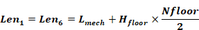
Pipe Length in the mechanical room (ft): Lmech=8
Height of each floor (ft): Hfloor=user input floor-to-floor height (ft)
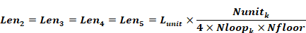
Length of each dwelling unit (ft):
 (see
Equation 7)
(see
Equation 7)
Length of recirculation pipe sections (ft):
Equation 31 Method WH-LOOPLEN
Pipe diameters for recirculation loop supply sections depend on the number of dwelling units being served and return section diameters depend only on building type, as follows:
Equation 32 Method WH-LOOPSZ
Dia1, Dia2, and Dia3: derived from Table B-4 based on Nunit1, Nunit2, and Nunit3
Dia4 = Dia5 = Dia6 = 0.75 in for low-rise multi-family building and hotel/motel less than four stories
Dia4 = Dia5 = Dia6 = 1.0 in for high-rise multi-family and hotel/motel more than three stories
where
Nunit1 = Number of dwelling units served by the loop section 1 =

Nunit2 = Nunit1
Nunit3 =

Note that Nunit values are not necessarily integers.
Branch pipe parameters include number of branches, branch length, and branch diameter. The number of branches in water heating system k is calculated as (note: not necessarily an integer):
Equation 33 Method WH-BRN

The branch pipe diameter shall be determined as follows:
Equation 34 Method WH-BRSZ
Diab: derived from Table B-4 based on Nunitb
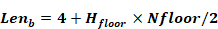
The branch length includes the vertical rise based on the number of floors in the building plus four feet of pipe to connect the branch to the recirculation loop.
Equation 35 Method WH-BRLEN
Proposed designs shall use the same branch configurations as those in the standard design. Therefore, compliance software does not need to collect branch design information.
|
Number
of dwelling
units served |
Loop pipe nominal size Dian in |
Branch
pipe nominal size Diab |
|
< 2 |
1.5 |
1 |
|
2 ≤ N < 8 |
1.5 | |
|
8 ≤ N < 21 |
2 | |
|
21 ≤ N < 42 |
2.5 | |
|
42 ≤ N < 68 |
3 | |
|
68 ≤ N < 101 |
3.5 | |
|
101 ≤ N < 145 |
4 | |
|
145 ≤ N < 198 |
5 | |
|
N >= 198 |
6 | |