
Once the hourly adjusted recovery load is determined for each water heater, the energy use for each water heater is calculated as described below and summed.
Storage water heaters are rated either by EF (energy factor) or the newer UEF (Uniform Energy Factor). The calculation algorithm for these devices derives a Load Dependent Energy Factor (LDEF) from EF. For water heaters rated with UEF, CBECC-Res calculates an equivalent EF.
The hourly energy use of storage gas water heaters is given by the following equation.
Equation 36
where
WHEUj = Hourly energy use of the water heater (Btu for fuel or kWh for electric); Equation 36 provides a value in units of Btu. For electric water heaters, the calculation result needs to be converted to the unit of kWh by dividing 3413 Btu/kWh.
HARLj = Hourly adjusted recovery load (Btu)
HPAFj = 1 for all non-heat pump water heaters
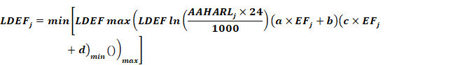
LDEFj = The hourly load dependent energy factor (LDEF) is given by Equation 37. This equation adjusts the nominal EF rating for storage water heaters for different load conditions.
Equation 37
where
a,b,c,d = Coefficients from the table below based on the water heater type
|
Coefficient |
Storage Gas |
|
a |
-0.098311 |
|
b |
0.240182 |
|
c |
1.356491 |
|
d |
-0.872446 |
|
LDEFmin |
.1 |
|
LDEFmax |
.90 |
AAHARLj
= Annual average hourly adjusted load (Btu) = j values for each
hour.
j values for each
hour.
EFj = Energy factor of the water heater (unitless). This is based on the DOE test procedure. EF for storage gas water heaters with volume less than 20 gallons must be assumed to be 0.58 unless the manufacturer has voluntarily reported an actual EF to the California Energy Commission.
CBECC-Res derives EFj from UEF for water heaters that are rated using updated DOE procedures.
UEF-rated consumer and residential-duty commercial instantaneous water heaters (gas and electric) are modeled on a minute-by-minute basis using procedures documented by Lutz (2019).
The hourly energy use for instantaneous gas or oil water heaters is given by , where the nominal rating is multiplied by 0.92 to reflect the impacts of heat exchanger cycling under real world load patterns.
Equation 38
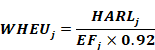
WHEUj = Hourly fuel energy use of the water heater (Btu)
HARLj = Hourly adjusted recovery load
EFj = Energy factor from the DOE test procedure (unitless) taken from manufacturers’ literature or from the CEC Appliance Database
0.92 = Efficiency adjustment factor
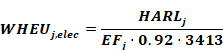
The hourly energy use for consumer instantaneous electric water heaters is given by the following equation.
Equation 39
where
WHEUj,elec = Hourly electric energy use of the water heater (kWh)
HARLj = Hourly adjusted recovery load (Btu)
EFj = Energy factor from DOE test procedure (unitless)
0.92 = Adjustment factor to adjust for overall performance
3413 = Unit conversion factor (Btu/kWh)
Mini-tank electric heaters are occasionally used with gas tankless water heaters to mitigate hot water delivery problems related to temperature fluctuations that may occur between draws. If mini-tank electric heaters are installed, the installed units must be listed in the CEC Appliance Database and their reported standby loss (in Watts) will be modeled to occur each hour of the year. (If the unit is not listed in the CEC Appliance Database, a standby power consumption of 35 W should be assumed.)
Equation 40

where
WHEUj,elec = Hourly standby electrical energy use of mini-tank electric water heaters (kWh)
MTSBLj = Mini-tank standby power (W) for tank j (if not listed in CEC Appliance
directory, assume 35 W)
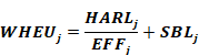
Energy use for large storage gas is determined by the following equations. Note: large storage gas water heaters are defined as any gas storage water heater with a minimum input rate of 75,000 Btu/h.
Equation 41
where
WHEUj = Hourly fuel energy use of the water heater (Btu)
HARLj = Hourly adjusted recovery load (Btu)
SBLj = Total Standby Loss (Btu/hr). Obtain from CEC Appliance Database or from AHRI certification database. This value includes tank losses and pilot energy. If standby rating is not available from either of the two databases, it shall be calculated as per Table F-2 of the 2015 Appliance Efficiency Regulations, as follows:
SBL = Q/800 + 110 (V)1/2, where Q is the input rating in Btu/hour, and V is the tank volume in gallons.
EFFj = Efficiency (fraction, not %). Obtained from CEC Appliance Database or from manufacturer’s literature. These products may be rated as a recovery efficiency, thermal efficiency or AFUE.
Energy use for these types of water heaters is given as follows:
Equation 42

where
WHEUj = Hourly fuel energy use of the water heater (Btu), adjusted for tank insulation.
HARLj =Hourly adjusted recovery load. For independent hot water storage tank(s) substitute HARLj from Section B3.
EFFj =Efficiency (fraction, not %) to be taken from CEC Appliance Database or from manufacturers literature. These products may be rated as a recovery efficiency, thermal efficiency or AFUE.
PILOTj =Pilot light energy (Btu/h) for large instantaneous. For large instantaneous water heaters, and hot water supply boilers with efficiency less than 89 percent assume the default is 750 Btu/hr if no information is provided in manufacturer’s literature or CEC Appliance Database.
0.92 =Adjustment factor used when system is not supplying a storage system.
Energy use for small electric water heaters is calculated as described in the HPWHsim Project Report (Ecotope, 2016) ) and in documents specified in Section B6 (see also study by NEEA referenced in Appendix F). The HPWH model uses a detailed, physically based, multi-node model that operates on a one-minute time step implemented using a suitable loop at the time-step level within CSE. Tank heat losses and heat pump source temperatures are linked to the CSE zone heat balance as appropriate. Thus, for example, the modeled air temperature of a garage containing a heat pump water heater will reflect the heat extracted.
HPWH can model three classes of equipment:
•Specific air-source heat pump water heaters identified by manufacturer and model. These units have been tested by Ecotope and measured parameters are built into the HPWH code.
•Generic air-source heat pump water heaters, characterized by EF and tank volume. This approach provides compliance flexibility. The performance characteristics of the generic model are tuned to use somewhat more energy than any specific unit across a realistic range of UEF values.
•Electric resistance water heaters, characterized by EF, tank volume, and resistance element power.
Another issue is that the HPWH hot water output temperature varies based on factors like control hysteresis and tank mixing. For compliance applications, it is required that all system alternatives deliver the same energy. To address this, the HPWH tank setup point is modeled at 125 °F and delivered water is tempered to ts. If the HPWH output temperature is above ts,it is assumed that inlet water is mixed with it (thus reducing Vi,t). If the output temperature is below ts, sufficient electrical resistance heating is supplied to bring the temperature up to ts (preventing under capacity from being exploited as a compliance advantage).
Several issues arise from integration of a detailed, short time step model into an hourly framework. HPWH is driven by water draw quantities, not energy requirements. Thus, to approximate central system distribution and unfired tank losses, fictitious draws are added to the scheduled water uses, as follows:
Equation 43
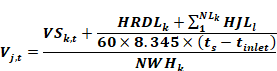
where
HRDLk = Hourly recirculation distribution loss (Btu), see Equation 15; HRDLk is non-zero only for multi-family central water heating systems
HJLl = Tank surface losses of the lth unfired tank of the kth system (Btu), see Equation 44
VSk = Hot water draw at the kth water heating system’s delivery point (gal)
Vj,t = Hot water draw (gal) on jth water heater for minute t
Another issue is that the HPWH hot water output temperature varies based on factors such as control hysteresis and tank mixing. For compliance applications, it is required that all system alternatives deliver the same energy. To address this, the HPWH tank setup point is modeled at 125 °F and delivered water is tempered to ts. If the HPWH output temperature is above ts,it is assumed that inlet water is mixed with it (thus reducing Vi,t). If the output temperature is below ts, sufficient electrical resistance heating is supplied to bring the temperature up to ts (preventing under sizing from being exploited as a compliance advantage).
The hourly jacket loss for the lth unfired tank or indirectly fired storage tank in the kth system is calculated as:
Equation 44
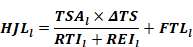
where
HJLl = The tank surface losses of the lth unfired tank of the kth system
TSAl = Tank surface area (ft2), see Equation 45
∆TS = Temperature difference between ambient surrounding tank and hot water supply temperature (ºF). Hot water supply temperature shall be 124ºF. For tanks located inside conditioned space use 75ºF for the ambient temperature. For tanks located in outside conditions use hourly dry bulb temperature ambient.
FTLl = Fitting losses; a constant 61.4 Btu/h
REIl = R-value of exterior insulating wrap; no less than R-12 is required
RTI l = R-value of insulation internal to water heater; assume 0 without documentation
Tank surface area (TSA) is used to calculate the hourly jacket loss (HJL) for unfired or indirectly fired tanks. TSA is given in the following equation as a function of the tank volume.
Equation 45
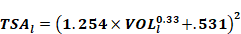
where
VOLl = Tank capacity (gal)
For single-family recirculation systems, hourly pumping energy is fixed as shown in Table B-6.
Multifamily recirculation systems typically have larger pump sizes, and therefore electrical energy use is calculated based on the installed pump size. The hourly recirculation pump electricity use (HEUP) is calculated by the hourly pumping schedule and the power of the pump motor as in the following equation.
Equation 46

where
HEUPk = Hourly electricity use for the circulation pump (kWh)
PUMPk = Pump brake horsepower (bhp)
ηk = Pump motor efficiency
SCHk,m = Operating schedule of the circulation pump, see Table B-2. The operating schedule for the proposed design shall be based on user input control method. The standard design operation schedule is demand control.
|
Hour |
Non-Demand Controlled Recirculation |
Demand-controlled Recirculation |
|
1 |
0.040 |
0.0010 |
|
2 |
0.040 |
0.0005 |
|
3 |
0.040 |
0.0006 |
|
4 |
0.040 |
0.0006 |
|
5 |
0.040 |
0.0012 |
|
6 |
0.040 |
0.0024 |
|
7 |
0.040 |
0.0045 |
|
8 |
0.040 |
0.0057 |
|
9 |
0.040 |
0.0054 |
|
10 |
0.040 |
0.0045 |
|
11 |
0.040 |
0.0037 |
|
12 |
0.040 |
0.0028 |
|
13 |
0.040 |
0.0025 |
|
14 |
0.040 |
0.0023 |
|
15 |
0.040 |
0.0021 |
|
16 |
0.040 |
0.0019 |
|
17 |
0.040 |
0.0028 |
|
18 |
0.040 |
0.0032 |
|
19 |
0.040 |
0.0033 |
|
20 |
0.040 |
0.0031 |
|
21 |
0.040 |
0.0027 |
|
22 |
0.040 |
0.0025 |
|
23 |
0.040 |
0.0023 |
|
24 |
0.040 |
0.0015 |
|
Annual Total |
350 |
23 |