Most condensers operate at a single speed and capacity and either run for longer or shorter periods of time during hotter or cooler weather, respectively. Short run times (aka, short cycling) reduce efficiency. Multi-speed condensers typically have a high and low speed. This can be accomplished by two separate compressors inside a single condenser, or by a single dual-stage compressor. During cooler weather (aka, part load times) the condenser will run in low speed for longer run periods. When needed, the condenser can run in high speed.
Variable-speed condensers are not limited to just high and low speeds. They can gradually ramp from lowest to highest speeds as needed.
There are several features that can indicate that a condenser is multi-speed. These include:
1. Product tags, labels and marketing names that indicate two-stage, dual-stage, multi-stage, etc.
2. Two compressors observed by looking down through the condenser fan.
3. High and low capacities or nominal tonnages indicated on nameplate.
The only definitive way to determine if the condenser is multi-speed or variable speed is to record the make and model number and find the manufacturer’s specifications.

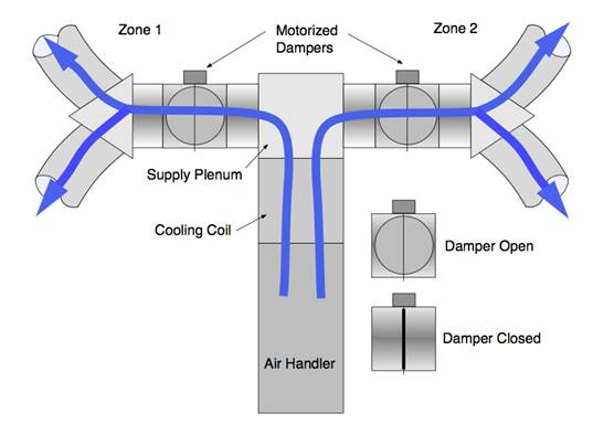
This diagram shows a common two-zone, two-damper system with both zones open (i.e., both zones are calling for cooling).
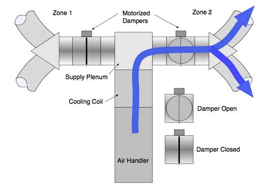
This diagram shows a common two-zone, two-damper system with zone 2 open (i.e., only zone 2 is calling for cooling).
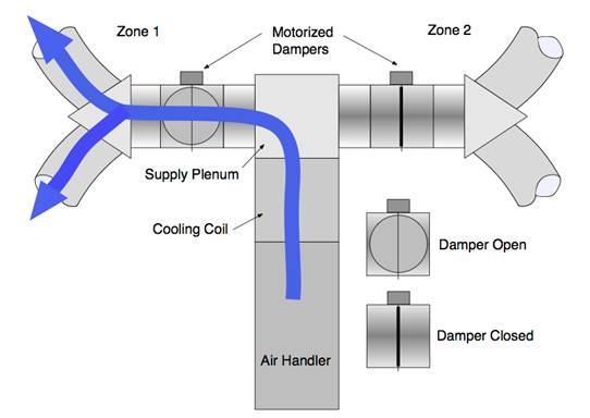
This diagram shows a common two-zone, two-damper system with zone 1 open (i.e., only zone 1 is calling for cooling).
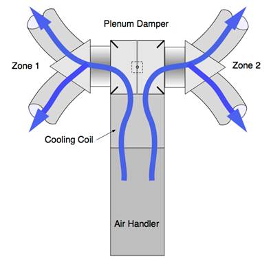
This diagram shows a common two-zone, single-damper system with both zones open (i.e., both zones are calling for cooling).
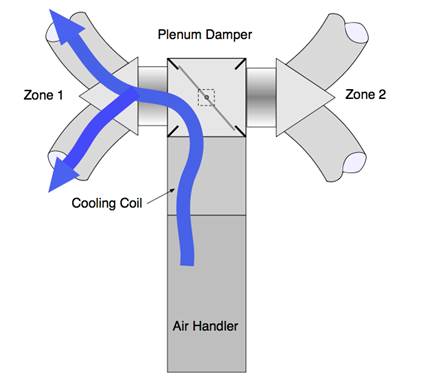
This diagram shows a common two-zone, single-damper system with zone 1 open (i.e., only zone 1 is calling for cooling).
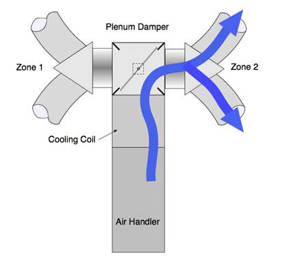
This diagram shows a common two-zone, single-damper system with zone 2 open (i.e., only zone 2 is calling for cooling).
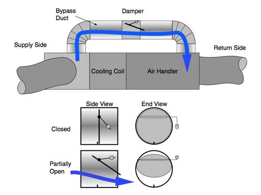
This diagram shows a common bypass duct/damper strategy. The bypass duct is sheet metal (which should always be insulated) and the damper is a barometric type. The details show how the damper opens when air pressure builds up against the adjustable weight. Sending heated or cooled air back into the space conditioning equipment can cause problems and reduce efficiency.
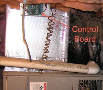
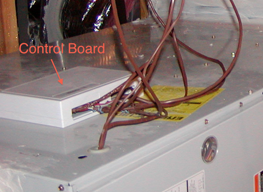
These photos show two examples of zonal control control-boards.
