The installer shall provide documentation that demonstrates the shading condition of the actual installation of the PV module is consistent with compliance with either JA11.3.1 or JA11.3.2 by one of the following methods:
a) Solar Assessment Tool. Use a solar assessment tool approved by the Executive Director to ascertain the extent of the shading conditions on the PV system from existing obstructions. At each measurement point, the tool placed on the PV array, leveled, and oriented consistent with the manufacturer’s instructions.
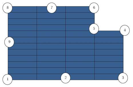
Measurements shall be made at all the major corners of the array with no adjacent measurement being more than 40 feet apart. (See example in Figure JA12-2.) The points of measurement shall be distributed evenly between two major corners if they are more than 40 feet apart such that the linear distance between any sequential points is no more than 40 feet. However, if any linear edge of the array has no obstructions that are closer than two times the height they project above the closest point on the array, then the intermediate measurements along that edge do not need to be made. Measurements made at each major corner and intermediate point shall be documented in the CF-2R Certificate of Installation.
The measurements shall be made either after the array has been installed or after the roof sheathing has been installed but prior to installation of the array. If the measurements are made prior to actual installations, the location of the array shall be marked on the roof plans and the measurement points shall be located on the roof and the measurements shall be made. The location of the array shall be marked on the roof so that the actuall installation is made consistent with the measurements. If the location of the array is changed during the construction process or new obstructions are introduced that did not exist at the time of the original measurements, the measurements will be re-determined after the actual installation.
b) Alternative Methods. Alternatively, for verification of solar access, the installer shall verify by an aerial satellite image(s), drone image(s), or other digital image(s) along with supporting documents showing the height of shading obstructions as well as the horizontal distance on the actual roof, and surrounding structures and trees, or by using an alternate method approved by the Executive Director to evaluate the solar access availability of the building location.

Figure JA12-2: Example of Points Where Measurement Shall Be Made Using a Solar Assessment Tool