The compliance software calculates energy generated by photovoltaic systems on an hourly basis using algorithms from PVWatts (ref). The routines are modified to better represent PV systems with and without sub-array power electronics (i.e., microinverters and DC power optimizers).
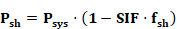
Power electronics are used to help minimize efficiency losses when the output of sub-array components (e.g., modules or cells) operate under different conditions. The largest driver of variation in conditions across a PV array is partial shading from nearby obstacles. A small fraction of shaded cells could lead to disproportionate reductions in PV power output. PVWatts, does not explicitly handle this effect. Literature (cite NREL) describes a shading impact factor (SIF) which is describes the ratio of relative power output to fraction shaded:
Where Psh is the power output of the shaded system, Psys is the power output of the unshaded system, and fsh is the fraction shaded.
A value of 1.0 implies that the power output declines proportionally to the fraction shaded. This is a theoretical minimum value of SIF in that it implies there are power electronics that are maintaining output consistent with the level of shading across the module. A value greater than 1.0 implies that shading has a disproportionate effect on system output.
How the individual cells within an array are shaded can have a significant impact on SIF. This is illustrated in a study on a PV module without power electronics:
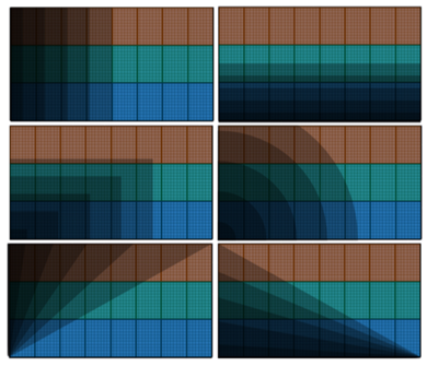
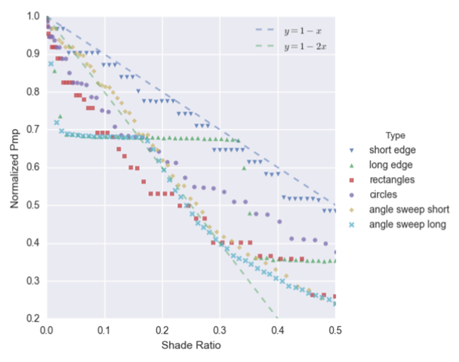
In this study the same module was shaded in different fashions (see first figure). For a given shade ratio, the actual output from the PV system can differ by 30% depending on which portions of the system are shaded (Note: the dotted lines in the first figure represent SIF values of 1.0 [y = 1 – 1.0*x] and 2.0 [y = 1 – 2.0*x] and serve as approximate bounds on the impact). Without cell-level fidelity in our shading model, it is impossible to know which specific cells are shaded at any given time. The compliance software will use a coarse approximation of SIF appropriate for panel and/or array level analysis.
SIF should also change with higher levels of irradiance as shown in this study (See figure 5). However, considering the coarseness of array-wide shading fraction (vs. cell-by-cell), accounting for this effect is not likely to provide a substantial increase in overall accuracy.
One problem with applying shading impact factors directly to the power output of the system is that there is a theoretical lower limit to PV production under shaded conditions: diffuse irradiance. Unless a cell is also blocked from diffuse solar (e.g., the shade is very close to the panel and blocking cells from the rest of the sky), all cells will receive a minimum level of incidence. To account for this, we propose introducing an alternative formulation using an “effective” plane-of-array incidence, where only the beam component is affected by shading.
Ipoa,eff = Ipoa,diff + Ipoa,beam,eff
Ipoa,beam,eff = max(Ipoa,beam*(1-SIF*fsh), 0.0)
The compliance software shall use an SIF value of 2.0 for central inverters (CEC default) and a value of 1.2 for systems with power electronics (based on a 40% shade loss recovery as defined in this paper--see Table 3).