Section 120.6(e) applies to all new compressed air systems and all additions or alterations to a compressed air system with a total installed compressor capacity ≥ 25 hp. An exception is given for medical gas compressed air systems serving healthcare facilities.
Key terms and definitions:
A. Trim compressor: a compressor that is designated for part-load operation, handling the short-term variable trim load of end uses, in addition to the fully loaded base compressor. In general, the trim compressor will be controlled by a VSD, but it also can be a compressor with good part-load efficiency. If the trim compressor does not have good part load efficiency broadly across the operating range, then it will take more compressors to meet the Energy Code requirements.
B. Base compressor: the opposite of a trim compressor, a base compressor is expected to be mostly loaded. If the compressed air system has only one compressor, the requirements of the Energy Code requires that the single compressor be treated as a trim compressor.
C. Specific power: the ratio of power to compressed air flow rate at a given pressure typically given in units of kW/100 acfm. The lower the specific power, the more efficient the compressor is at a given compressed air load.
D. Total effective trim capacity: the combined effective trim capacity of all trim compressors where effective trim capacity for each compressor is the range of capacities in acfm, which are within 15 percent of the specific power at the most efficient operating point. This is displayed in Figure 10-42.
E. Largest net capacity increment: the largest increase in capacity when switching between combinations of base compressors that is expected to occur under the compressed air system control scheme. See Example 10-54.
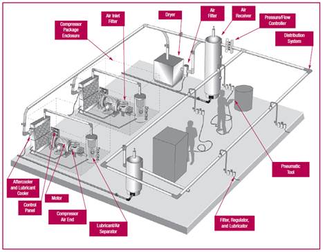
F. Primary Storage: tanks or other devices that store compressed air. Also known as an air receiver, they reduce peak air demand on the compressor system and reduce the rate of pressure change in a system. As primary storage, these devices are near the air compressors and are differentiated from remote storage that might be near an end-use device.
G. Interconnection Piping: Interconnection piping is considered to be the piping between compressor discharge outlets, conditioning equipment such as dryers and aftercoolers, and often the primary storage receiver prior to delivery to the main header. Interconnection piping often connects multiple compressors, as well.
H. Main Header Piping: Main header piping is the piping that delivers air from the interconnection piping to any distribution piping or sub-headers. This piping often begins at the outlet of a storage receiver or flow controller and terminates at distribution piping out to different areas of a facility. In some cases, there may not be main header piping if the distribution piping is simple enough to contain only a single diameter distribution loop or loops.
I. Distribution Piping: Distribution piping includes all piping after the main header and transports air to service lines.
J. Service Line Piping: Service lines, often called drops, are typically the smallest diameter piping that delivers air from distribution piping to individual or groups of end-uses. Any tubing such as flexible hoses or plastic tubing within end-uses is not considered service line piping and is not covered by the compressed air pipe sizing or leak testing requirements.
Figure 10-40: Typical Compressed Air System Components

Source: Improving Compressed Air System Performance: A Sourcebook for Industry, USDOE 2003
There are six main mandatory requirements in this section:
a. Trim compressor and storage - §120.6(e)1,
b. Controls - §120.6(e)2,
c. Monitoring - §120.6(e)3,
d. Leak testing of compressed air piping - §120.6(e)4,
e. Pipe sizing - §120.6(e)5, and
f. Compressed air system acceptance - §120.6(e)6.
This requirement targets the performance of a compressed air system across the full range of the system.
There are two paths to comply with this requirement:
1. Using a variable-speed drive (VSD) controlled compressor(s) as the trim compressor (§120.6(e)1A):
•The VSD trim compressor(s) must have a capacity (acfm) of at least 1.25 times the largest net capacity increment (see Example 10-54).
•Primary storage of at least one gallon per acfm (1 gal/acfm) of the largest trim compressor.
2. Using a compressor or set of compressors as the trim compressor (§120.6(e)1B) without requiring a VSD-controlled compressor:
•The trim compressor(s) must have a total effective trim capacity no less than the largest net capacity increment.
•Primary storage of at least two gallons per acfm (2 gal/acfm) of the largest trim compressor.
•Effective trim capacity is the range of compressed air flow rates where the specific power (W/acfm) is no greater than 115% of the minimum specific power (Figure 10-42).
Both paths aim to reduce the amount of cycling of fixed-speed compressors by using a better-suited compressor that operates well in part-load.
A. Compliance Option 1: VSD-controlled Trim Compressor
Many base-load compressors are designed to provide peak efficiency near the rated capacity with a significant drop off in efficiency at lower flow rates (in acfm). Compressed air systems often avoid the losses in efficiency associated with part-load compressed air flows by staging multiple compressors so that in most cases base compressors operate near full load. A trim compressor is designed to have close to peak efficiency over a broad range of compressed air flow rates. To make sure the compressed air system is operating efficiently over the entire range, it is important to have a trim compressor sized to handle the gaps between base compressors. The minimum size of the trim compressor(s) is determined calculating the Largest Net Capacity Increment - the biggest step increase between combinations of base compressors.
With equally sized compressors, this is fairly intuitive: in a system with a two-100 hp (434 acfm) rotary screw compressor system, the largest step increase would be the size of one of the compressors (434 acfm). For systems with uneven compressor sizes, it requires going through the following steps:
1. Determine all combinations of base compressors (including all compressors off).
2. Order these combinations in increasing capacity.
3. Calculate the difference between every adjacent combination.
4. Choose the largest difference.
This largest difference is what must be covered by the trim compressor(s) to avoid a control gap.
Once the largest net capacity increment is calculated, this value can be used to satisfy the first compliance option. Option 1 mandates that the rated capacity of the VSD compressor(s) be at least 1.25 times the largest net increment.
For Compliance Option 1, the system must include primary storage that has a minimum capacity of 1 gallon for every acfm of capacity of the largest trim compressor.
Example 10-61
Question
Given a system with three base compressors with capacities of 200 acfm (Compressor A), 400 acfm (Compressor B), and 1,000 acfm (Compressor C), what is the Largest Net Capacity Increment?
Answer
As shown in the image below, there are eight possible stages of capacity ranging from 0 acfm with no compressors to 1,600 acfm with all three compressors operating. The largest net increment is between Stage 4 with Compressors A and B operating (200+400=600 acfm) to stage 5 with compressor C operating (1,000 acfm)
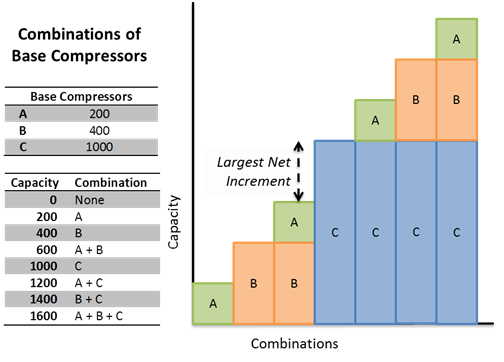
For this system the Largest Net Capacity Increment is 1,000 acfm-600 acfm = 400 acfm
Example 10-62
Question
Using the system from the previous example, what is the minimum rated capacity of VSD compressor(s) that are needed to comply with Option 1?
Answer
As previously shown, the Largest Net Capacity Increment is 1,000 acfm-600 acfm = 400 acfm. The minimum rated capacity for VSD compressor(s) is 400 acfm X 1.25 = 500 acfm.
Example 10-63
Question
What is the required minimum primary storage capacity for the trim compressor from the previous example to comply with Option 1?
Answer
Assuming there is a VSD compressor with a rated capacity of 500 acfm, per §120.6(e)1A, it must have 1 gallon of storage per acfm of rated capacity or 500*1 = 500 gallons of storage.
B. Compliance Option 2: Other Compressors as Trim Compressor
The second compliance option offers more flexibility but requires looking at both the largest net capacity increment of the system, as well as the effective trim capacity of the trim compressor(s).
The effective trim capacity is the range across which a trim compressor has adequate part-load performance. Performance is measured in power input over air volume output or specific power (kw/100 acfm). Many VSD compressors come with a compressor performance graph in a CAGI data sheet that looks similar to the graph in Figure 10-41.
Figure 10-41: Example Compressor Power vs. Capacity Curve
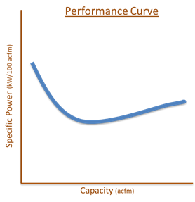
The capacity of the compressor is along the x-axis, while the power is on the y-axis. The curve in Figure 10-41 is a typical shape of a performance curve for a VSD compressor. The lower the specific power, the more energy-efficient the compressor is at that condition.
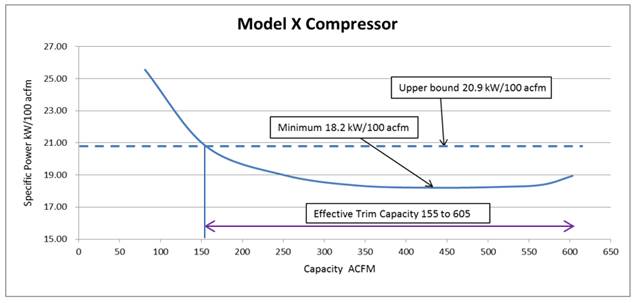
The effective trim capacity uses the minimum of the compressor power vs. capacity curve to determine the range of adequate part-load performance. This can be done in the following steps and is illustrated in the graph below.
1. Find the minimum specific power across the range.
2. Find the upper bound by calculating 1.15 times the minimum specific power.
3. Determine the endpoints of the capacity (acfm) where the specific power is less than or equal to the upper bound.
4. The capacity difference in units of acfm between these two endpoints is the effective trim capacity.
Figure 10-42: Determination of Effective Trim Capacity from a Compressor Curve
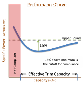
This definition of effective trim capacity, along with the largest net capacity increment of the system, is used to size the trim compressor appropriately in the next section.
For Compliance Option 2, the system must include primary storage that has a minimum capacity of 2 gallons for every acfm of capacity of the largest trim compressor.
Example 10-64
Question
Continuing with the system from the previous examples, what is the required minimum effective trim capacity of the trim compressor(s) to comply with Option 2?
Answer
As previously shown, the largest net capacity increment is (1,000 acfm) – (600 acfm) = 400 acfm. Per §120.6(e)1 the minimum effective trim capacity is equal to the largest Net Capacity Increment or 400 acfm.
Example 10-64
Question
A manufacturer provided the
following data for its compressor; would this provide the minimum effective trim
capacity for this system to comply with Option 2?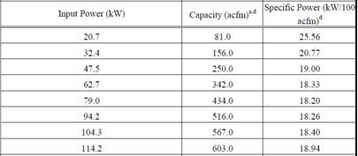
Answer
From the manufacturer’s data, the minimum specific power is 18.2 kW/100 acfm. The upper limit would be 18.2 * 1.15 = 20.9 kW/100 acfm. Interpolating from the manufacturer’s data, this appears to go from 155 acfm to 605 acfm for an effective trim capacity of 605-155= 450 acfm. This is larger than the largest net capacity increment of 400 acfm, so this compressor would comply as a trim compressor for this system.
Example 10-65
Question
What is the required minimum primary storage capacity for the trim compressor from the previous example to comply with Option 2?
Answer
This compressor has a rated capacity of 603 acfm. Per §120.6(e)1B, it must have 2 gallons of storage per acfm of rated capacity or 603*2 = 1,206 gallons of storage.
The last example used a VSD compressor, but other technologies can be used for compliance option 2 such as a compressor with unloaders and sufficient compressed air storage to achieve relatively high part-load efficiencies over a broad range of compressed airflow rates. Generally, higher levels of storage improve part-load performance. The following data, in Figure 10-43 and for this example, were generated from theoretical curves used in AirMaster+, a tool created by the U.S. Department of Energy.
Figure 10-43: Normalized Efficiency Curves for a Screw Compressor with Load/Unload Controls for Various Amounts of Storage
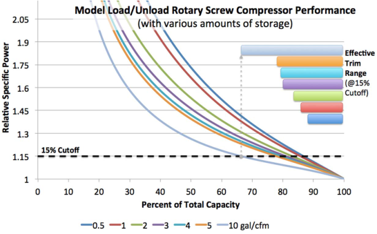
Source: Derived from Fact Sheet 6 – Compressed Air Storage, Improving Compressed Air Storage: A Sourcebook for Industry, U.S. Department of Energy, 2003
The next example examines a 250-hp load-unload, single-stage, rotary-screw compressor coupled with 10 gallons/cfm of storage. This combination of compressor and storage was chosen to meet the part-load performance mandated by code.
Example 10-66
Question
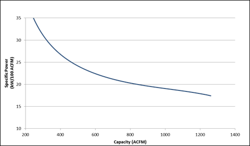
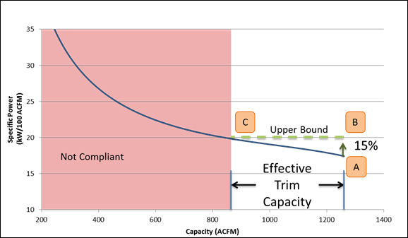
Part-load data were approximated below for a 250-hp load-unload, single-stage, rotary-screw compressor (with a capacity of 1,261 acfm) coupled with 10 gallons/cfm of storage. Would this provide the minimum effective trim capacity for this system to comply with Option 2 using the previous examples?
Answer
Using the previous examples, a
compressor with an effective trim capacity of at least 400 acfm is
necessary.
Looking at the graph, the minimum specific power (labeled as A below) occurs at full load - a capacity of 1,261 acfm, with a specific power of 17.4 kW/100 acfm. Using this minimum specific power, the upper bound is 17.4 * 1.15 = 20.01 kW/100acfm or 15% higher than the minimum specific power. This puts the ends of the effective trim capacity at 1261 acfm (labeled as B) and 845 acfm (labeled as C), resulting in an effective trim capacity of 1261 – 845 = 416 acfm. This is larger than the largest net capacity increment of 400 acfm, so this compressor would comply as a trim compressor for this system. The shaded area labeled “not compliant” is the portion of the compressor capacity that does not contribute to the total system effective trim capacity.
Example 10-67
Question
What is the required minimum primary storage capacity for the trim compressor from the previous example to comply with Option 2?
Answer
This compressor has a rated capacity of 1,261 acfm, and per §120.6(e)1B it must have 2 gallons of storage per acfm of rated capacity or 1261 * 2 = 2,522 gallons of storage.
However, a minimum of 10 gallons of storage per acfm was needed for the screw compressor with load/unload controls to have a large enough effective trim capacity. The minimum required primary storage to meet the effective trim capacity and storage requirements in §120.6(e)1B is 10 gal per acfm of rated trim compressor capacity; thus, the minimum primary storage capacity required is 1,261 * 10 = 12,610 gallons.
Example 10-68
Question
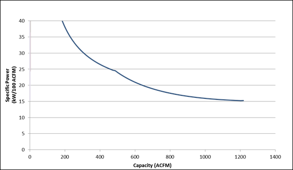
Part-load data were approximated below for a 250-hp variable-capacity compressor. Would this provide the minimum effective trim capacity for this system to comply with Option 2?
Answer
Using the previous examples, a compressor with an effective trim capacity of at least 400 acfm is necessary.
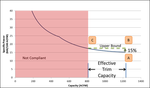
Looking at the graph, the minimum specific power (labeled as A below) occurs at full load - a capacity of 1,218 acfm, with a specific power of 15.3 kW/100 acfm. Using this minimum specific power, the upper bound is 15.3 * 1.15 = 17.56 kW/100 acfm or 15% higher than the minimum specific power. This puts the ends of the effective trim capacity at 1,218 acfm (labeled as B) and 804 acfm (labeled as C), resulting in an effective trim capacity of 1218 – 804 = 414 acfm. This is larger than the largest net capacity increment of 400 acfm so this compressor would comply as a trim compressor for this system.
Example 10-69
Question
What is the required minimum primary storage capacity for the trim compressor from the previous example to comply with Option 2?
Answer
This compressor has a rated capacity of 1,218 acfm, and per §120.6(e)1B it must have 2 gallons of storage per acfm of rated capacity or 1,218 * 2 = 2,236 gallons of storage.
This section applies to compressed air systems with more than one on-line compressor and a combined power of ≥100 hp. This section requires an automated control system that will optimally stage the compressors to minimize energy for the given load. With new systems, this ideally means that at any given load, the only compressors running at part-load are the trim compressors. Because not all systems are required to upgrade the trim compressor, the installed controls must stage the compressors in the most efficient manner.
This requirement also mandates the measurement of air demand. The control system must be able to measure or calculate the current system demand (in terms of actual cubic feet per minute of airflow). There are two ways to accomplish this, including, but not limited, to the following sensors:
1. A flow meter
2. A combination of pressure transducers and power meters
This measure supports the ongoing optimization and tuning that is necessary to maintain compressed air system function and efficiency. This is done through specifying monitoring system minimum requirements for the compressed air system. Monitoring of compressed air pressure, input electrical power, and airflow enables identification of any poorly functioning plants, mechanical degradation, or increases in leak loads. Identifying these issues allows for informed maintenance and repair to systems that have unacceptable levels of waste, malfunctions, and inefficiencies. Monitoring of compressed air should be integrated into plant management protocols and facility operations as it can not only be a source for sustaining optimal energy efficiency but also a metric for factory health in an industrial setting. Monitoring of compressed air loads and efficiency is necessary for sustained system performance and energy benefits from the other requirements in §120.6(e).
Any new compressed air plant with combined nominal capacity equal to or greater than 100 hp nominal and any existing plant expanded or altered such that the combined capacity is equal to or greater than 100 hp must have a monitoring system with the following:
1. Measurement of system pressure.
2. Measurement of amps or power of each compressor.
3. Measurement or determination of total flow from the compressed air plant in cfm.
4. Data logging of pressure, power in kW, airflow in cfm, and compressed air specific efficiency in kW/100 cfm at intervals of 5 minutes or less.
5. Maintained data storage of at least the most recent 24 months.
6. Visual trending display of each recorded point, load, and specific energy.
Note that §120.6(e)3B allows for measurement of compressor input power in either amps or direct real power measurement in kW. Amps is allowable to accommodate the common practice of measuring amps and combining with voltage and power factor to estimate input power.
Note that §120.6(e)3C allows for measurement of compressed airflow output through either direct measurement of airflow or through calculation of airflow from performance data. These alternatives accommodate the two primary means of measuring airflow in the compressed air market.
Data storage and display can be accomplished at any potential user interface, from onboard packaged unit displays to integration into plant SCADA systems. Where possible, alarms for leak load limits, specific efficiency limits, and any other desired metrics should be programmed.
Example 10-70
Question
What data acquisition would be required to meet §120.6(e)3 part C, Measurement or determination of total airflow from compressors in cfm?
Answer
Part C specifies that two options for monitoring compressed air flow (cfm), either directly or indirectly a maximum of 5 minute intervals. Direct measurements will typically take the form of a probe or inline air flow meter. Indirect calculations would require the use of measurement of true power (kW) and estimating the airflow using compressor performance data. Performance data sheets can be provided by the air compressor manufacturer and/or national industry associations. This performance data is typically provided in the form of tables and/or performance curves. For many air compressors specific efficiency (kW/100 cfm) is a standard unit. The airflow can be indirectly measured by dividing the measured power by the specific efficiency.
Example 10-71
Question
How can the data gathered from equipment required by §120.6(e)3 be used for compressed air energy management?
Answer
Two primary energy benefits of the monitoring requirements come from maintenance of system efficiency and management of leak loads:
1. Compressed air system energy performance is typically quantified by specific power in kW/100 cfm. By monitoring specific power of a compressed air system, efficiency can be continuously managed and optimized over time. Facility staff should use regularly observe specific power monitoring to identify if and when the system begins to operate poorly. Staff should first identify what their compressor or compressed air specific power is after initial commissioning or optimization efforts. This serves as the baseline. If the specific power increases over time, facility staff should investigate or engage with their compressed air service providers to identify the source of performance degradation. This performance degradation will likely take the form of discrete, obvious spikes in specific power due to acute malfunctions or gradual increases over time. These increases in specific power affect the energy used for every cfm at all hours. Therefore, correction of any root causes or recommissioning will save energy for the entire compressed air system under all loads and hours.
2. Compressed air leak loads typically grow over time in most facilities due to unavoidable wear and tear. These leak loads are often 20-40% of total usage, resulting is large excessive, unproductive energy use and reliability issues at compressed air tools and end-uses. Monitoring of airflow in cfm can be used to identify when leak loads have grown to a level that warrants corrective action. Good practice is to target leak loads of about 10% with regular leak repair and management processes.
The monitoring system will allow facilities to observe loads in cfm for their plant. If the cfm monitoring shows that loads are growing over time without any corresponding production or operational changes, leak loads are likely growing. This leak load, energy use, and cost can be quantified by observing the cfm growth. This provides facility staff operational and financial justification for correcting leaks as well as showing the returns for doing so. Another useful approach for determining leak loads is to observe cfm trends during after-hours, breaks, or weekends with the compressors still on. This can very clearly show leak loads since most or all the output will likely be going to leaks if there are no tools or machines in use.
The monitoring system may be configured to flag or send alerts to facility staff when issues such as these are automatically identified by the monitoring system. This is optional and dependent of the monitoring system capabilities but can help streamline the process for many facilities.
This requirement targets the quality installation of new compressed air piping in both new construction and additions and alterations of existing piping. Piping greater than 50 adjoining feet in length shall be pressure tested to ensure minimal leakage rates after installation. The piping shall be pressurized to the system design pressure and help for at least 30 minutes without losing pressurization as indicated by test gauges measuring directly at the tested length of piping.
The pressure test should use dial pressure gauges conforming to the California Plumbing Code sections 318.3, 318.4, and 318.5. In the 2019 California Plumbing Code, these specify the following:
•Required pressure tests exceeding 10 psi (69 kPa) but less than or equal to 100 psi (689 kPa) shall be performed with gauges of 1 psi (7 kPa) incrementation or less.
•Required pressure tests exceeding 100 psi (689 kPa) shall be performed with gauges incremented for 2 percent or less of the required test pressure.
•Test gauges shall have a pressure range not exceeding twice the test pressure applied.
Piping less than or equal to 50 feet in adjoining length and connections shall be pressurized and manually inspected with a leak-detecting fluid.
In either case, if the piping fails to maintain pressure or leaks are detected, repairs or corrections must be made to the piping to eliminate the leak sources prior to re-testing.
The purpose of this requirement is to ensure quality installation of new piping. In many cases, it can be extremely difficult and disruptive to repair leaks in hard-to-reach, mission-critical piping once a system is commissioned and operational. Leak testing is necessary to ensure these issues are avoided at construction and are often standard or best practices by installing contractors.
This requirement targets the performance of a compressed air systems to minimize frictional losses.
For service line piping a minimum pipe diameter of ¾ inch is required. Flexible hoses and tubing at the end-uses are not covered by this requirement.
For compressor room interconnection, main header piping, and distribution piping there are two paths for compliance:
1. Piping section average velocity:
•Interconnection and main header piping shall be sized so that at coincident peak flow conditions, the average velocity in the segment of pipe is no greater than 20 ft/sec.
•Distribution piping shall be sized so that at coincident peak flow conditions, the average velocity in the segment of pipe is no greater than 30 ft/sec.
2. Piping total pressure drop:
•Frictional pressure loss at coincident peak loads are less than 5 percent of operating pressure between the compressor and end-use or end-use regulator.
For the piping total pressure drop pathway, it should be noted that the pressure drop is based on piping frictional pressure losses and does not include pressure drops across components such as dryers, flow controllers, regulators, and other non-piping components.
Example 10-72
Question
An existing compressed air has installed a new 30-foot subheader with three 10-foot branch lines, what must be done to ensure this additional compressed air piping will comply?

Answer
This system is installing a total of 60 feet of adjoining compressed air system piping. To comply with §120.6(e)4, the section of piping must be isolated and undergo pressure testing for a minimum of 30 minutes with no perceptible drop in pressure. To comply with §120.6(e)5, the service line piping must have a minimum inner diameter of ¾ inch and must comply with either §120.6(e)5B OR §120.6(e)5C.
§120.6(e)5B requires a calculation of pipe size based on a targeted maximum pipe velocity. Inner diameter can be estimated through the following equation

Where:
v = velocity of air in feet per minute
d = inside diameter of pipe in inches
Q = Maximum expected flowrate through pipe in cubic feet per minute
For the section of piping above, to minimize frictional losses by sizing the pipe for a maximum of 30 ft/second (1800 feet/minute), the resultant diameter would be 1.01 inches. Rounding to the most appropriate diameter would be 1 inch (inner diameter) pipe.
§120.6(e)5C would require the calculation of the total piping pressure drop. To satisfy this requirement the piping frictional pressure loss would need to be lower than 5 percent of the operating pressure at coincident peak load. This can be in the form of compressed air modeling software or hand calculations. Hand calculations typically reference available reference tables from handbooks and manufacturers.
Examining the section of pipe added above, the pressure loss over the section of pipe can be estimated using reference tables that will typically provide pressure loss (psi) per 100 ft of pipe. Assuming the added section is the section of pipe furthest from the compressor, we can estimate the pressure loss introduced by the added pipe.
Assuming:
Line Pressure = 100 PSIG
Air Flow = 10 CFM
Pipe Diameter = 1/2 inch
Online reference tables yield a pressure loss of 0.4 psi per 100 foot of schedule 40 steel pipe. As all branch lines are equivalent in length and further assuming all have an equivalent diameter (and area), then the length of pipe the pressure drop will need to be calculated for is 40 feet (30 feet + 10 feet). This would yield the following pressure loss:


The resultant pressure loss of the section of pipe added would be 0.16 psi. Again, assuming this section of the pipe is the furthest from the compressor, a similar calculation would need to be performed across the total length of existing pipe leading to the end of the 10 foot branch line. To meet the requirements of §120.6(e)5C the total pressure loss calculated in this fashion should not exceed 5 percent of the operating pressure. E.g., for a given operating pressure of 115 psig, the total frictional pressure loss calculated would need to be less than 5.75 psig.
Example 10-73
Question
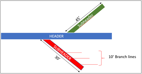
Using the distribution system from the previous example, an additional 45-foot subheader in a separate location of the compressed air distribution network. What testing and pipe sizing requirements will apply?
Answer
For the situation above when installing a new 30 foot subheader and three 10 foot branch lines, the maximum velocity would be 30 feet/second. To determine the inside diameter of the pipe the only information that will need to be referenced is the pressure loss due to flow through pipes which
As the additional 45-foot subheader is a separate section of piping in the same network but adjoining to an existing header that will not be altered, only §120.6(e)4 will apply. Furthermore, pressurized leak testing is not required on this section of piping and connections may be tested with noncorrosive leak-detecting fluid or other leak detecting methods.
New systems and altered systems that are subject to the trim compressor requirements of §120.6(e)1, staging control requirements of §120.6(e)2, or monitoring requirements of §120.6(e)3 must be tested per NA7.13.
There are no prescriptive measures for compressed air systems.
There are six requirements in this section for compressed air systems additions and alterations:
a. Trim compressor and storage - §120.6(e)1,
b. Controls - §120.6(e)2,
c. Monitoring - §120.6(e)3,
d. Leak testing of compressed air piping - §120.6(e)4,
e. Pipe sizing - §120.6(e)5, and
f. Acceptance - §120.6(e)6.
These requirements apply to existing systems that are being altered and that have a total compressor capacity ≥ 25 hp. These requirements will be triggered by replacing a compressor, adding a compressor, or removing a compressor.
These requirements do not apply to:
•Repairing a compressor.
•Replacing a compressor drive motor.
•Adding compressed air controls.
•Adding air dryers.
•Adding oil separators.
•Adding compressed air storage capacity.
•Removing an air compressor without adding any air compressors.
For alterations or additions to an existing compressed air system, requirement §120.6(e)1 for trim compressor size and storage do not apply when the total combined added or replaced compressor horsepower is less than the average per-compressor horsepower of all compressors in the system, or when all added or replaced compressors are variable speed drive compressors and the compressed air system includes primary storage of at least one gallon per actual cubic feet per minute (acfm) of the largest trim compressor.
For alterations or additions to an existing compressed air system, requirement §120.6(e)2 for controls applies only when the compressed air system has three or more compressors and a combined horsepower rating of more than 100 horsepower.
For alterations or additions to an existing compressed air system, requirement §120.6(e)3 for monitoring applies only when the compressed air system has a combined horsepower rating of more than 100 horsepower. Monitoring equipment can be used to identify changes in system performance for the purpose of identifying inefficiencies such as air leaks.
For alterations or additions to an existing compressed air system, requirement §120.6(e)4 for leak testing of compressed air piping applies to added or altered piping with leak testing requirements based on the length of adjoining pipe added or altered.
For alterations or additions to an existing compressed air system, requirement §120.6(e)5 for pipe sizing only applies when the added or altered piping is greater than 50 adjoining feet in length. For service line piping a minimum pipe diameter of ¾ inch is required. Flexible hoses and tubing at the end-uses are not covered by this requirement. For compressor room interconnection, main header piping, and distribution piping there are two paths for compliance as described in 10.8.2.5.
For alterations or additions to an existing compressed air system, requirement §120.6(e)6 for compressed air system acceptance testing will apply based on which other compressed air system requirements are required. For example, if an addition or alteration to a compressed air system triggers the controls requirement in 120.6(e)3, then the acceptance requirements associated with controls are also required.
Example 10-74
Question
If a 50 hp compressor was added to a compressed air system with only one existing 100 hp compressor, would the requirements of §120.6(e) apply?
Answer
Each subsection of §120.6(e) would need to be evaluated to determine which requirements are applicable and which requirements are not.
Requirements for trim and compressor and storage are not applicable because 50 hp is Less than the average per-compressor horsepower of all compressors in the system. Requirements for controls in §120.6(e)2 are not applicable because the compressed air system has less than three compressors. Requirements for leak testing of compressed air piping in §120.6(e)4 and pipe sizing in §120.6(e)5C are not applicable because compressed air piping is not being added.
Requirements for monitoring in §120.6(e)3 are required because the system has a combined horsepower rating greater than 100 hp. Additionally, compressed air system acceptance requirements in §120.6(e)6 pertaining to the monitoring system will also be applicable.