This section contains information about lighting controls that must be installed regardless of the method used to comply with the lighting power requirements.
All lighting controls and equipment must comply with the applicable requirements in §110.9, 130.1, 130.2, and must be installed in accordance with the manufacturer’s instructions (§130.0(d)).
Mandatory nonresidential indoor lighting controls include the following:
1. Manual area controls, allowing on and off control for each area separately.
2. Multilevel controls, allowing the ability to use all, some, or none of the light in an area.
3. Shut-off controls, which, automatically shut off or reduce light output when a space is vacant.
4. Automatic daylighting controls, which separately control general lighting in the daylit area based on the amount of daylight in the space.
5. Demand-responsive lighting controls, which are capable of receiving and automatically responding to a demand response signal.
§130.1(a) of Part 6; §10-103(a)2 of Part 1
Each building area shall provide lighting controls that allow lighting in that area to be manually turned on and off. Manual area controls allow building occupants to control the light while they are in the space.
The manual area controls shall meet the following requirements:
1. Be readily accessible.
EXCEPTION: Restrooms having two or more stalls, parking areas, stairwells, corridors, and areas of the building intended for access or use by the public may use a manual control not accessible to unauthorized personnel.
2. Be located in the same enclosed area with the lighting it controls.
EXCEPTION 1: For malls and atria, main entry lobbies, auditorium areas, dining areas, retail merchandise sales areas, wholesale showroom areas, commercial and industrial storage areas, general commercial and industrial work areas, convention centers, arenas, psychiatric and secure areas in healthcare facilities, and other areas where placement of a manual area control poses a health and safety hazard, the manual area control shall instead be located so that a person using the control can see the lights or area controlled by that control, or visually signal or display showing the current state of the controlled lighting.
EXCEPTION 2: Healthcare facility restrooms and bathing rooms intended for a single occupant can have lighting controls located outside the enclosed area but directly adjacent to the door.
3. Separately control general, floor display, wall display, window display, case display, decorative, and special effects lighting such that each type of lighting can be turned on and off without turning on or off other types of lighting or other equipment. Scene controllers may comply with this requirement provided that at least one scene turns on general lighting only, and the control provides a means to manually turn off all lighting.
For egress lighting required by the California Building Code, up to 0.1 W/sq. ft. of indoor lighting may be continuously illuminated during occupancy. Egress lighting that complies with this wattage limitation is not required to comply with manual area control requirements if:
1. The means of egress area is shown on the building plans and specifications submitted to the local enforcement agency under Section §10-103(a)2 of Part 1 (California Code of Regulations Title 24).
2. The egress lighting controls are inaccessible to unauthorized personnel.
Multilevel lighting controls allow the lighting level to be adjusted to accommodate how a room is being used.
This requirement applies to general lighting in enclosed spaces 100 sq. ft. or larger with a connected general lighting load greater than 0.5 W/sq. ft. General lighting does not include task, display, or decorative lighting.
The multilevel control must meet the minimum required control steps and uniformity requirements in Table 130.1-A. The minimum required control steps are determined by the type of light source or luminaire being controlled.
For some light sources and luminaires, dimming can be implemented in steps or over a continuous range. Continuous dimming provides a smoother transition of light levels compared to stepped dimming.
Classrooms with a connected general lighting load of 0.6 W/sq. ft. or less shall have a minimum of one control step between 30 percent and 70 percent of full rated power, regardless of luminaire type.
EXCEPTION: The following applications are not required to comply with the multilevel lighting control requirements:
1. An area enclosed by ceiling height partitions with only one luminaire containing no more than two lamps or with only one inseparable SSL luminaire
2. Restrooms
Table 5-2 (From Table 130.1-A): Multilevel Lighting Controls and Uniformity Requirements
|
Luminaire Type |
Minimum
Required Control Steps |
Uniform level of illuminance shall be achieved by: |
|
LED luminaires and LED light sources |
Continuous dimming 10-100% |
Continuous dimming 10-100% |
|
Line-voltage sockets except |
Continuous dimming 10-100% |
Continuous dimming 10-100% |
|
Low-voltage incandescent systems |
Continuous dimming 10-100% |
Continuous dimming 10-100% |
|
Fluorescent luminaires |
Continuous dimming 20-100% |
Continuous dimming 20-100% |
|
GU-24 sockets rated for fluorescent ≤ 20 watts Pin-based compact fluorescent ≤ 20 watts2 Linear fluorescent and U-bent fluorescent ≤ 13 watts |
Minimum one step between |
Continuous dimming or Stepped dimming or Switching alternate lamps in a luminaire or Separately switching circuits in multicircuit track with a minimum of two circuits. |
|
Track Lighting |
Minimum one step between |
Continuous dimming or Stepped dimming or Separately switching circuits in multicircuit track with a minimum of two circuits. |
|
Linear Fluorescent and U-bent fluorescent > 13 watts |
Minimum one step in each range: |
Stepped dimming or Continuous dimming or Switching alternate lamps in each luminaire, having a minimum of 4 lamps per luminaire, illuminating the same area in the same manner. |
|
Other light sources, including HID and Induction |
Minimum one step between |
Stepped dimming or Continuous dimming or Switching alternate lamps in each luminaire, having a minimum of 2 lamps per luminaire, illuminating the same area and in the same manner. |
1. Full rated input power of driver, ballast, and lamp, corresponding to maximum ballast
factor.
2. Includes only pin-based twin tube, multiple twin tube, and spiral
lamps.
§130.1(c)|topic=(c) Shut-OFF Controls.
All installed indoor lighting shall be equipped with controls that are able to automatically reduce lighting power when the space is typically unoccupied.
EXCEPTION: Healthcare facilities are not required to meet the shut off control requirements.
Shut off controls can be used to automatically turn off or reduce lighting when the spaces are not occupied. For example, an office building is typically unoccupied at night and on weekends; automatic shutoff controls ensure that lighting is off during these periods.
In addition to lighting controls installed to comply with §130.1(a) (manual on and off controls located in each area) and §130.1(b) (multilevel lighting controls) , all installed indoor lighting shall be equipped with shut off controls that meet the following requirements (§130.1[c]1):
1. One or more of the following automatic shut off controls:
•Automatic time-switch control
•Other control capable of automatically shutting off all lighting when the space is typically unoccupied
2. Separate controls for lighting on each floor, other than lighting in stairwells
3. Separate controls for a space 5,000 square feet or smaller enclosed by ceiling-height partitions. Spaces larger than 5,000 square feet will have more than one separately controlled zone (where each zone does not exceed 5,000 square feet)
EXCEPTION: The area controlled may not exceed 20,000 square feet in the following function areas: malls, auditoriums, single-tenant retail, industrial, convention centers, and arenas
The following applications are exempt from the shut off control requirements of §130.1(c)1:
•An area that is in 24-hour use every day of the year.
•Lighting complying with the occupant sensing control requirements of §130.1(c)5 instead of §130.1(c)1.
o This exception applies to those areas where occupant sensing controls are required to shut off all lighting. These areas include offices 250 sq. ft. or smaller, multipurpose rooms of less than 1,000 sq. ft., classrooms of any size, conference rooms of any size, or restrooms of any size.
•Lighting complying with the partial- off occupant sensing control requirements of §130.1(c)7 instead of §130.1(c)1.
o This exception applies to those areas where partial off occupant sensing controls are required. These areas include stairwells and common area corridors 130.1(c)7Athat provide access to guestrooms and dwelling units in accordance with §130.1(c)7A, or parking garages, parking areas, and loading and unloading areas in accordance with §130.1(c)7B.
•Lighting up to 0.1 watts per sq. ft. may be continuously illuminated for egress illumination. Lighting providing “egress illumination,” as used in the California Building Code, shall provide no less light than required by California Building Code Section 1008 while in the partial-off mode.
•Electrical equipment rooms covered by Article 110.26(D) of the California Electrical Code.
•Lighting that is designated as emergency lighting that is connected to an emergency power source or battery supply and intended to function in emergency mode only when normal power is absent.
Countdown timer switches may be used to comply with the automatic shut off control requirements in §130.1(c)1 only in closets smaller than 70 sq. ft. and server aisles in server rooms.
The maximum timer setting shall be 10 minutes for closets and 30 minutes for server aisles.
Automatic time-switch controls other than an occupant sensing control shall include a manual override control that complies with §130.1(a) and allows the lighting to remain on for no more than two hours when an override is initiated.
EXCEPTIONS: In the following functional areas, the override time may exceed two hours if a captive-key override is used:
•Malls
•Auditoriums
•Single-tenant retail
•Industrial
•Laboratories
•Arenas
An automatic holiday shut off feature shall be incorporated with the automatic time-switch control that turns off all loads for at least 24 hours, and then resumes the normally scheduled operation.
EXCEPTIONS: The following are not required to incorporate the holiday shut off feature:
•Retail stores and associated malls
•Restaurants
•Grocery stores
•Churches
•Theaters
Lighting in the following areas shall be controlled with occupant sensing controls to automatically shut off all of the lighting in 20 minutes or less after the control zone is unoccupied. In addition, controls shall be provided that allow the lights to be manually shut off in accordance with §130.1(a) regardless of the sensor status:
a. Offices 250 sq. ft. or smaller
b. Multipurpose rooms smaller than 1,000 sq. ft.
c. Classrooms of any size
d. Conference rooms of any size
e. Restrooms of any size
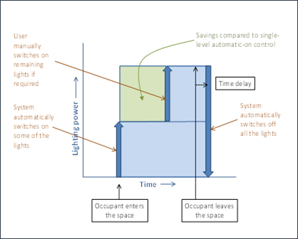
In areas required by §130.1(b) to have multilevel lighting controls, the occupant sensing controls shall function as one of the following:
a. A partial-on occupant-sensing control capable of automatically activating between 50 and 70 percent of controlled lighting power (requires lights to be turned ON manually to 100 percent) and automatically turning lights off when the space is unoccupied
b. A vacancy-sensing control that automatically turns lights off after an area is vacated and requires lights to be turned on manually
For areas not required by §130.1(b) to have multilevel lighting controls, occupant sensing controls may function as one of the following:
a. A normal occupant-sensing control with automatic on and off functionality
b. A partial-on occupant-sensing control
c. A vacancy-sensing control
Figure 5-7: Functional Diagram for Partial-ON Occupant Sensor

Image Source: California Energy Commission
Offices larger than 250 sq. ft. are required to be equipped with an occupant sensing control that manages the HVAC thermostat setup, setback, and ventilation (§120.1[d]and §120.2(e)3). The occupant sensing control for the space must be capable of signaling to the HVAC system the occupancy status of the space independent of the lighting load status.
Using the same occupancy sensors for the lighting and the HVAC system immediately alerts occupants if the occupancy sensors have failed, as the lights would turn off when the space is occupied. An occupancy sensor failure might not be as readily apparent if it controlled the HVAC system only. However, it is not a requirement that the lighting and HVAC systems be controlled by the same occupancy sensor. This method of controlling cooling, ventilation, and lighting satisfies the requirements of §120.1(d)5, §120.2(e)3, and §130.1(c)|topic=(c) Shut-OFF Controls., so no additional shut off controls are required in these spaces (except for lighting associated with the egress path, which may remain energized when the building is unoccupied).
In addition to the basic shut off requirements in §130.1(c)1, §130.1(c)6 requires full- or partial off occupant sensing controls to turn off or reduce lighting when an area is unoccupied.
In warehouse aisle ways and open areas, certain library book stack aisles, stairwells, and corridors, lighting power must reduce by at least 50 percent when the areas are unoccupied. The decision to reduce or turn lighting off may be made by the designer.
Lighting in these spaces must also comply with §130.1(c)1, which requires lighting to be capable of shutting off when the building is unoccupied. If a partial off occupancy sensor is used to reduce lighting when a space is unoccupied, it can be paired with an automatic time switch to shut lighting off when the building is typically unoccupied.
Figure 5-8 Functional Diagram for Partial Off Occupant Sensor
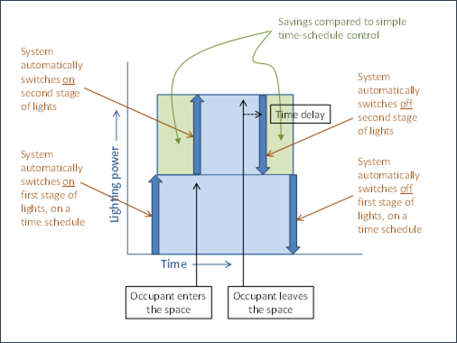
Image Source: California Energy Commission
A. In aisle and open areas in warehouses, lighting shall be controlled with occupant sensing controls that automatically reduce lighting power by at least 50 percent when the areas are unoccupied. The occupant sensing controls must have independent zoning for each aisle, and the aisle zones must not extend beyond the aisle into the open area of the warehouse.
EXCEPTIONS: The following conditions exempt the lighting system from this requirement, but it must meet the additional listed requirements:
1. In aisle ways and open areas in warehouses in which the installed lighting power is 80 percent or less of the value allowed under the Area Category Method, occupant sensing controls shall reduce lighting power by at least 40 percent (instead of the 50 percent required above).
2. When metal halide lighting or high-pressure sodium lighting is installed in warehouses, occupant sensing controls shall reduce lighting power by at least 40 percent (instead of the 50 percent required above). This exception is due to limitations of dimming or bilevel ballast technology for high-intensity discharge (HID) light sources.
B. In the following library book stack aisles, lighting shall be controlled with occupant sensing controls that automatically reduce lighting power by at least 50 percent when the areas are unoccupied:
1. Library book stack aisles 10 feet or longer that are accessible from only one end
2. Library book stack aisles 20 feet or longer that are accessible from both ends
The occupant sensing controls shall independently control lighting in each aisle way and shall not control lighting beyond the aisle way being controlled by the sensor.
C. In corridors and stairwells, lighting shall be controlled by occupant sensing controls that separately reduce the lighting power in each space by at least 50 percent when the space is unoccupied. The occupant sensing controls shall be capable of turning the lighting fully on automatically only in the separately controlled space and shall be automatically activated from all designed paths of egress.
D. In office spaces greater than 250 sq. ft., general lighting shall be controlled by occupant sensing controls that meet all of the following requirements. These requirements apply exclusively to luminaires providing general lighting. Luminaires not meant to provide general lighting can either be controlled following the same occupant sensing controls requirements as general lighting, or be controlled as specified in §130.1(c)1 using time-switch controls or separate occupant sensing controls.
i. The occupant sensing controls shall be configured so that lighting is controlled separately in control zones not greater than 600 sq. ft. For luminaires with an embedded occupant sensor capable of reducing power independently from other luminaires, each luminaire can be considered its own control zone.
ii. In 20 minutes or less after the control zone is unoccupied, the occupant sensing controls shall uniformly reduce lighting power in the control zone by at least 80 percent of full power. Control functions that switch control zone lights completely off when the zone is vacant meet this requirement.
iii. In 20 minutes or less after the entire office space is unoccupied, the occupant sensing controls shall automatically turn off lighting in all control zones in the space.
iv. In each control zone, lighting shall be allowed to automatically turn on to any level up to full power upon occupancy within the control zone. When occupancy is detected in any control zone in the space, the lighting in other control zones that are unoccupied shall operate at no more than 20 percent of full power.
EXCEPTION to the mandatory occupant sensing controls for offices greater than 250 sq. ft.: Under-shelf or furniture-mounted task lighting that is already controlled by a local switch and either a time clock or an occupancy sensor does not need to be included in the control zones of the occupant sensing controls.
Example 5-5: An Office With Luminaires Serving Different Lighting Purposes
An office of 2,584 square feet has three types of luminaires, as shown in the figure below:
1.Overhead luminaires providing general lighting to the cubicles (the 28 purple rectangles).
2.Linear lights over display cases near the wall highlighting the objects in the cases (bottom left and right).
3.Wall wash lighting along the wall highlighting artwork (bottom center).
Only the overhead luminaires providing general lighting are subject to the occupant sensing control requirements in §130.1(c)6D. Different approaches and options to meet the requirements are discussed in the next example. The linear display lighting and wall wash are grouped together and controlled by a time clock to comply with the shut off requirements in §130.1(c)1.
Figure 5-9 (for Example 5-5) An Office Plan With Occupant Sensing Control Zone Layout
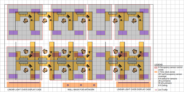
Image Source: Energy Solutions
Example 5-6: Occupant Sensing Control Zones for Office Spaces Greater Than 250 Square Feet
In office spaces greater than 250 sq. ft., the occupant sensing controls must be configured such that general lighting in the space is divided into separate control zones, and the size of each control zone must be 600 sq. ft. or less.
The figure below provides an example of the same 2,584 square foot office as in the previous example that meets this requirement. Display lighting and wall wash are omitted as they do not need to comply with this requirement. In this case, the office is divided into eight occupant sensing control zones, each controlled by an occupant sensor. The occupant sensors in this example have a circular coverage pattern with a radius of 13.5 feet, resulting in a coverage area of 573 square feet, which meets the 600 square feet or less per control zone requirement. Each circle in the image represents the coverage area of the occupant sensor located at the center of the circle. The evenly spaced purple rectangles represent 2’x4’ luminaires that provide general lighting in the office, and the luminaires within each circle are controlled by the occupant sensor at the center of the circle. If a luminaire is in two or more circles, it is controlled by the closest occupant sensor.
The size of each control zone is at the discretion of the practitioner, as long as it is not larger than 600 square feet. The control zones within the office space do not need to be equal in size. If each occupant sensing control zone in an office is 250 square feet or less and the prescriptive compliance path is used, consider taking advantage of the power adjustment factor (PAF) provided in §140.6(a)2I|topic=2. Reduction of wattage through controls. for occupant sensing controls in offices larger than 250 square feet. Refer to Section 5.6.2 for more information on the PAF.
Figure 5-10 (for Example 5-6) An Office Plan With Occupant Sensing Control Zone Layout
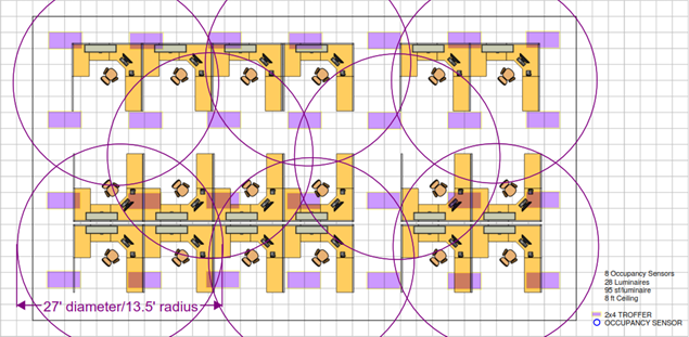
Image Source: Energy Solutions
Example 5-7: Occupant Sensing Control Zone in a Large Office Using Power Adjustment Factor
The figure below shows another occupant sensing control zone design for the same 2,584 sq. ft. office. In this design, 15 occupant sensors are used to meet the requirement, and each sensor has a circular coverage pattern with a radius of 8.5 feet, resulting in a coverage area of 227 sq. ft. Because each sensor controls 227 sq. ft., which is less than 250 sq. ft. but more than 126 sq. ft., a PAF of 0.20 can be used per Table 140.6-A. Refer to §140.6(a)2I|topic=2. Reduction of wattage through controls. and Section 5.6.2 of this compliance manual for detailed requirements on using the PAF for occupant sensing controls in offices larger than 250 square feet.
Note: Using PAFs for occupant sensing controls is dependent on the square footage that each occupant sensor covers and not the number of occupant sensors used. For example, if each of the 15 occupant sensors in the figure below had a coverage area greater than 250 sq. ft., the design would not qualify to use the PAF.
Figure 5-11 (for Example 5-7) An Office Plan With Occupant Sensing Control Zone Layout
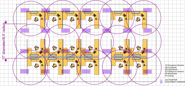
Image Source: Energy Solutions
Example 5-8: Occupant Sensing Control Zones for Luminaires With Integral Occupant Sensors
For luminaires with an integral occupant sensor that are capable of reducing power independently from other luminaires, each luminaire can be considered as its own control zone, and the size of the control zone equals the coverage area of the luminaire-integrated occupant sensor. This configuration is likely to result in occupant sensing control zones 250 sq. ft. or smaller. So, if using the prescriptive compliance path, consider taking advantage of the PAF provided in §140.6(a)2I|topic=2. Reduction of wattage through controls. for occupant sensing controls in offices larger than 250 square feet. Refer to Section 5.6.2 for more about using the PAF.
Note: Each luminaire with an integral occupant sensor can be considered as its own control zone only if they are commissioned to reduce power independently from other luminaires. Several lighting systems allow “grouping” luminaires with an integral occupant sensor. In such a grouping configuration, all luminaires within the group will operate to provide the designed task light level as long as one luminaire-integrated sensor detects occupancy. Similarly, all luminaires will reduce power to 20 percent or less only after no occupant is detected by any of the luminaire-integrated sensors within the group for 20 minutes. In this case, the total area covered by a group of luminaire-integrated occupant sensors is considered as a single occupant sensing control zone and shall be 600 square feet or less.
The figure below provides an example of the same 2,584 sq. ft. office using luminaires with an integral occupant sensor, with each luminaire commissioned to reduce power independently from the other luminaires. In this case, there are 28 luminaires; therefore, there are 28 occupant sensing control zones. The coverage area of each sensor (and therefore the size of each control zone) is 100 sq. ft. This occupant sensing control zone design not only meets the control requirements, but is eligible for a PAF of 0.30 since each occupant sensing control zone is less than 125 sq. ft. (see Table 140.6-A).
Figure 5-12 (for Example 5-8): An Office Plan With Occupant Sensing Control Zone Layout
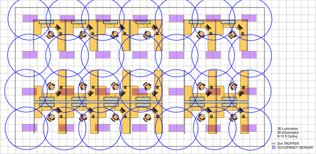
Image Source: Energy Solutions
Example 5-9: Occupant Sensing Controls for an Office Greater Than 250 Square Feet With a Single Control Zone
An office space larger than 250 sq. ft. but smaller than or equal to 600 sq. ft. may have a single control zone for the entire office as long as the field of view of the occupant sensor is able to cover the entire office. The figure below shows a shared office space of 400 square feet as an example. In this case, a single occupant sensor is able to cover the entire office and, therefore, meets the requirement.
Figure 5-13 (for Example 5-9) An Office Plan With Occupant Sensing Control Zone Layout
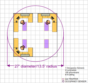
Image Source: Energy Solutions
Notes About Occupant Sensing Ventilation Controls And Occupant Sensing Lighting Controls
Note 1: Occupant sensing ventilation controls are required in spaces meeting, or 7. Occupant sensing ventilation controls for offices greater than 250 sq. ft. are now required because this space type meets both criteria. Because of this, occupant sensing zone controls for the space-conditioning system are also required. Refer to §120.1(d)5, and §120.2(e)3 in the Energy Code as well as Sections 4.3.1.1.1.37 and 4.5.1.1.1.8 of this manual to ensure occupant sensor ventilation controls and occupant sensing zone controls are properly implemented on the mechanical systems. Corridors are another space type covered by §130.1(c)6, where ventilation air is allowed to go to zero during occupied standby mode, and thus are required to meet occupant sensing ventilation control requirements.
Note 2: This occupant sensing controls requirement in §130.1(c)6D does not negate other lighting controls provisions in §130.1. For example, for office spaces greater than 250 sq. ft. where automatic daylighting controls are also required per §130.1(d), lighting in the occupied occupant sensing control zones shall be dimmed in response to the available daylight. Refer to §130.1(f) in the Energy Code and Section 5.4.6 of this manual to ensure the proper interactions among the required lighting controls.
In stairwells and common area corridors to guest rooms of hotel/motels, in parking garages and parking areas, and in loading and unloading areas, lighting is required to have partial off occupant sensing controls instead of meeting the shut off requirements of §130.1(c)1.
Lighting in these spaces may operate full time at the minimum setback level and is not required to be shut off after hours. The decision to turn the lights off fully may be made by the designer.
A. Lighting in stairwells and common area corridors that provide access to guestrooms of hotel/motels shall be controlled with occupant sensing controls that automatically reduce lighting power by at least 50 percent when the areas are unoccupied. The occupant sensing controls shall be capable of automatically turning the lighting fully on only in the separately controlled space and shall be automatically activated from all designed paths of egress.
This permits the lights to remain on at a setback level continuously. The zoning of the controls requires careful consideration of paths of egress to ensure that sensor coverage in the zone is adequate.
EXCEPTION: In common area corridors and stairwells in which the installed lighting power is 80 percent or less of the value allowed under the Area Category Method, occupant sensing controls shall reduce power by at least 40 percent (instead of the normally required 50 percent).
B. In parking garages, parking areas, and loading and unloading areas, general lighting shall meet the following requirements:
1. Be controlled by occupant sensing controls having at least one control step between 20 percent and 50 percent of design lighting power.
2. No more than 500 watts of rated lighting power shall be controlled together as a single zone.
3. A reasonably uniform level of illuminance shall be achieved in accordance with the applicable requirements in Table 5-1 (Table 130.1-A of the Energy Code).
4. Occupant sensing controls shall be capable of automatically turning the lighting fully on only in each separately controlled space.
5. The occupant sensing controls shall be automatically activated from all designed paths of egress.
For these spaces, lighting power must be reduced by at least 50 percent of the design lighting power, and the lighting must be reduced while maintaining similar levels of uniformity to the full power conditions. The zoning of the controls requires careful consideration of paths of egress to ensure that the sensor coverage in the zone is adequate. The wattage limits per zone will typically not permit entire floors of a garage to be on a single zone.
EXCEPTION: Metal halide luminaires meeting both of the following criteria shall be controlled by occupant sensing controls having at least one control step between 20 percent and 60 percent of design lighting power:
•A “lamp plus ballast” means system efficacy greater than 75 lumens per watt. (The lamp plus ballast mean system efficacy is the rated mean lamp lumens at 40 percent of lamp life divided by the ballast rated input watts.)
•When metal halide is used for general lighting in parking garages, parking areas, and loading and unloading areas.
The requirement for metal halide luminaires to have a control step between 20 percent and 60 percent is a limitation of the dimming or bilevel ballast technology in HID light sources.
Interior areas of parking garages are classified as indoor lighting for compliance with §130.1(c)7B.
The parking areas on the roof of a parking structure are classified as outdoor hardscape and shall comply with the applicable provisions in §130.2. Controls requirements in §130.1(c)7B do not apply to open rooftop parking.
Daylighting can be used as an effective strategy to reduce electric lighting energy use by reducing electric lighting power in response to available daylight. Section 130.1(d) addresses mandatory requirements for automatic daylighting controls.
Automatic daylighting controls are required in daylit zones to automatically reduce general lighting when sufficient daylight is available.
Terms:
Daylit Zone is the floor area under skylights or next to windows. Types of Daylit Zones include Primary Sidelit Daylit Zone, Secondary Sidelit Daylit Zone, and Skylit Daylit Zone.
Primary Sidelit Daylit Zone is the area in plan view directly adjacent to each vertical glazing, one window head height deep into the area, and window width plus 0.5 times window head height wide on each side of the rough opening of the window, minus any area on a plan beyond a permanent obstruction that is 6 feet or taller as measured from the floor.
Secondary Sidelit Daylit Zone is the area in plan view directly adjacent to each vertical glazing, two window head heights deep into the area, and window width plus 0.5 times window head height wide on each side of the rough opening of the window, minus any area on a plan beyond a permanent obstruction that is 6 feet or taller as measured from the floor.
Skylit Daylit Zone (see below).
Window Head Height — The vertical distance from the finished floor level to the top of a window or vertical fenestration.
There are three types of daylit zones: primary sidelit daylit zone, secondary sidelit daylit zone, and skylit daylit zone.
A. Skylit Daylit Zone is the rough area in plan view under each skylight, plus 0.7 times the average ceiling height in each direction from the edge of the rough opening of the skylight, minus any area on a plan beyond a permanent obstruction that is taller than one-half the distance from the floor to the bottom of the skylight.
Note: Modular furniture walls should not be considered a permanent obstruction.
The bottom of the skylight is measured from the bottom of the skylight well (for skylights having wells), or the bottom of the skylight if no skylight well exists.
For determining the skylit daylit zone, the geometric shape of the skylit daylit zone shall be identical to the plan view geometric shape of the rough opening of the skylight; for example, the skylit daylit zone for a rectangular skylight must be rectangular. For a circular skylight, the skylit daylit zone must be circular.
Figure 5-14: Example of Skylit Daylit Zone Layout in Overhead View
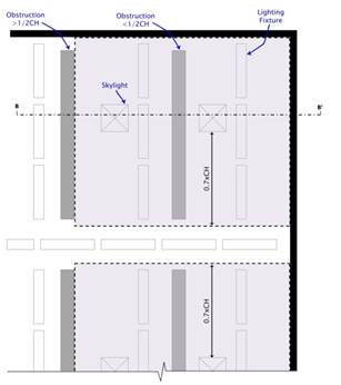
Image Source: California Energy Commission
Figure 5-15: Example of Skylit Daylit Zone Layout in Side View
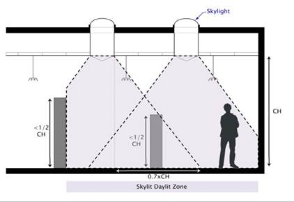
Image Source: California Energy Commission
B. PRIMARY SIDELIT DAYLIT ZONE is the area in plan view directly adjacent to each vertical glazing, one window head height deep into the area, and window width plus 0.5 times window head height wide on each side of the rough opening of the window, minus any area on a plan beyond a permanent obstruction that is 6 feet or taller as measured from the floor.
Note: Modular furniture walls should not be considered a permanent obstruction.
Figure 5-16: Example of Primary Sidelit Daylit Zone Layout in Overhead View
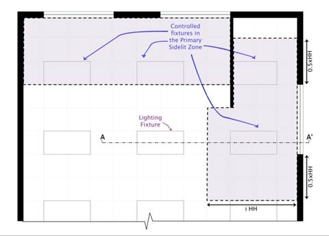
Image Source: California Energy Commission
Figure 5-17: Example of Primary Sidelit Daylit Zone Layout in Side View
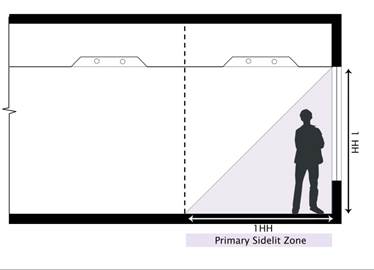
Image Source: California Energy Commission
C. SECONDARY SIDELIT DAYLIT ZONE is the area in plan view directly adjacent to each vertical glazing, two window head heights deep into the area, and window width plus 0.5 times window head height wide on each side of the rough opening of the window, minus any area on a plan beyond a permanent obstruction that is 6 feet or taller as measured from the floor.
Note: Modular furniture walls should not be considered a permanent obstruction.
Figure 5-18: Example of Secondary Sidelit Daylit Zone in Side View
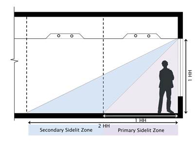
Image Source: California Energy Commission
Figure 5-19: Example of Secondary Sidelit Daylit Zone in Overhead View
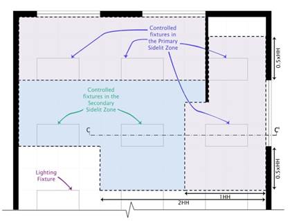
Image Source: California Energy Commission
Automatic daylighting controls are required for general lighting in skylit daylit zones, primary sidelit daylit zones, and secondary sidelit daylit zones.
The requirements are as follows:
A. Luminaires providing general lighting that are at least 50 percent in the skylit daylit zone, primary sidelit daylit zone, or secondary sidelit daylit zone shall be controlled independently by automatic daylighting controls that meet the applicable requirements:
1. All skylit daylit zones, primary sidelit daylit zones, and secondary sidelit daylit zones must be shown on the building plans.
2. The automatic daylighting controls shall provide separate control for general lighting in each type of daylit zone. General lighting luminaires in the skylit daylit zone must be controlled separately from those in the primary sidelit daylit zone and secondary sidelit daylit zone.
In spaces where skylights are near exterior walls with windows, the skylit daylit zone may overlap with either the primary or secondary sidelit daylit zone. The skylit daylit zone takes precedence, and the general lighting luminaires in the overlapping area must be controlled as part of the skylit daylit zone.
3. Where the primary sidelit daylit zone and the secondary sidelit daylit zone overlap, such as in corner spaces, the primary sidelit daylit zone takes precedence and the general lighting luminaires in the overlapping area must be controlled as part of the primary sidelit daylit zone.
4. General lighting luminaires that are long such as linear pendants, strip lights, tape lights, and cover lights shall be segmented into control sections so that lighting is controlled separately in skylit daylit zones, primary sidelit daylit zones, secondary sidelit daylit zones, and nondaylit zones. Each segment must be 4 feet or shorter and be separately controlled according to the type of daylit zone in which the segment is primarily located.
For luminaires in skylit daylit zones, primary sidelit daylit zones, and secondary sidelit daylit zones, automatic daylighting controls must be installed and configured according to the following requirements:
1. Automatic daylighting controls must provide multiple lighting levels with at least the number of control steps specified in Table 5-1 (Table 130.1-A of the Energy Code).
When the requirements of §130.1(d) are triggered by the addition of skylights to an existing building and the lighting system is not recircuited, the daylighting control is not required to meet the multilevel requirements in §130.1(d). The daylighting control may provide on/off control in accordance with §141.0(b)2 for alterations.
2. For each space, the combined illuminance from the controlled lighting and daylight shall not be less than the illuminance from controlled lighting when no daylight is available.
In the darkest portion of the daylit zone, the control should not overdim the lights.
3. When the daylight illuminance is greater than 150 percent of the illuminance provided by the controlled lighting when no daylight is available, the controlled lighting power in that daylight zone shall be reduced by a minimum of 90 percent.
The best control would fully dim the system when daylight levels in the darkest portion of the daylit zone are at 100 percent of the illuminance from controlled lighting when no daylight is available. The 150 percent/90 percent requirement allows some tolerance for error while obtaining most of the energy savings.
4. Photosensors shall be located so they are not readily accessible to unauthorized personnel. The location where calibration adjustments are made to automatic daylighting controls shall be readily accessible to authorized personnel and may be inside a locked case or under a cover that requires a tool for access. Access to controls can be limited by placing locks or screws on enclosures or under a cover plate so a tool or key is needed to gain access. Though not required, commissioning and retrocommissioning of the control are simplified if the calibration adjustments are readily accessible to authorized personnel so that a lift or a ladder is not required to access the location where calibration adjustment are made.
Some controls have wireless remotes for adjusting settings. This allows one person with a light meter and the wireless calibration tool to be located at the edge of the daylit zone and make the calibration adjustments without having to run back and forth between taking the measurement and making the adjustment.
EXCEPTIONS: Automatic daylighting controls are not required for any of the following conditions:
•Areas under skylights where it is documented that existing adjacent structures or natural objects block direct sunlight for more than 1,500 daytime hours per year between 8 a.m. and 4 p.m.
•Areas adjacent to vertical glazing below an overhang, where the overhang covers the entire width of the vertical glazing, no vertical glazing is above the overhang, and the ratio of the overhang projection to the overhang rise is greater than 1.5 for south, east, and west orientations or greater than 1 for north orientations.
•Rooms in which the combined total installed wattage of general lighting power in skylit daylit zones and primary sidelit daylit zone is less than 120 watts are not required to have daylighting controls for those zones.
•Rooms where the total installed wattage of general lighting power in secondary sidelit daylit zones is less than 120 watts are not required to have daylighting controls for those zones.
•Rooms that have a total glazing area of less than 24 square feet.
•Luminaires in sidelit daylit zones in retail merchandise sales and wholesale showroom areas.
Example 5-10: Complying With the 150 Percent of the Design Illuminance Daylighting Requirement
When the illuminance received from daylight is greater than 150 percent of the design illuminance (or nighttime electric lighting illuminance), the general lighting power in the daylit zone must reduce by a minimum of 90 percent.
For example, a space has 500 watts of general lighting power in the daylit zones. The design illuminance for the space is 50 foot-candles (fc). When the available daylight in the space reaches 75 fc (that is, 150 percent of 50 fc), then the power consumed by the general lighting in the daylit zones should be 50 watts or lower.
Without checking all points in the daylit zone served by controlled lighting, verifying that the requirements are met at a worst-case location far away from windows or skylights is sufficient. This location is called the “Reference Location.”
Example 5-11: Daylighting Controls and Opaque Curtain Walls
Question
Are automatic daylighting controls required for daylit zones adjacent to opaque glazing in curtain walls per §130.1(d) and §140.6(a)?
Answer
No. The automatic daylighting control requirements do not apply to daylit zones adjacent to opaque curtain walls. The Energy Code defines sidelit daylit zones as the areas in plan view directly adjacent to each vertical glazing. Glazing is a fenestration product that is defined as being transparent or translucent. Note: Automatic daylighting control requirements will apply to daylit zones adjacent to transparent or translucent curtain walls.
Example 5-12: Sidelit Daylit Zone for a Recessed Window
Question
Are sidelit daylit zones determined differently for an area adjacent to a window that is recessed in a bay?
Answer
No. The sidelit daylit zones will be determined the same way as for a window that is not recessed. The primary sidelit daylit zone extends out one window head height deep into the space and one-half a window head height to each side of the rough opening of the window. The only difference is that the sidelit daylit zone of a recessed window will be reduced by the incursion of the bay and exterior walls into the sidelit daylit zone, as shown in the following figure.
Figure 5-20: (Example 5-12) Sidelit Daylit Zone Layout for a Bay Window
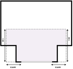
Image Source: California Energy Commission
In a parking garage area having a combined total of 36 square feet or more of glazing or opening, luminaires providing general lighting that are in the combined primary and secondary sidelit daylit zones shall be controlled independently from other lighting in the parking garage by automatic daylighting controls.
Parking areas on the roof of a parking structure are outdoor hardscape and automatic daylighting control requirements do not apply to these spaces.
The primary differences between the automatic daylight control requirements in parking garages and the rest of interior lighting spaces are the following:
•The primary and secondary sidelit daylit zones are controlled together in parking garages, whereas they must be separately controlled in other spaces. However, it is permissible that in either space type, a single sensor can be used if the control system can make the appropriate light level adjustments in each zone.
•In parking garages, when the daylight illuminance is greater than 150 percent of the illuminance provided by the controlled lighting when no daylight is available, the controlled lighting power in the combined primary and secondary sidelit daylight zone shall be reduced by 100 percent. (In other interior spaces, the lighting power must be reduced by 90 percent.) Egress lighting for the parking garage may be controlled, but the controls must employ a fail-safe mechanism that ensures that the egress lighting is functioning and stays on if the photocell fails.
Exceptions: Automatic daylighting controls are not required in the following parking garage areas:
•Parking garage areas where the total installed wattage of general lighting in the primary and secondary sidelit daylit zones is less than 60 watts
•Parking garage areas with a total glazing or opening area less than 36 square feet
•Luminaires in the daylight adaptation zone
§130.1(e)|topic=(e) Demand Responsive Controls.; §110.12
Buildings with nonresidential lighting systems having a total installed 130.1(b) lighting power of 4,000 watts or greater that are subject to the multilevel requirements in §130.1(b) must meet demand-responsive lighting control requirements.
The demand-responsive control must be capable of reducing the total lighting power by 15 percent or greater. The lighting power reduction must meet the uniformity requirements of Table 130.1-A
EXCEPTION: Spaces where a health or life safety statute, ordinance, or regulation does not permit the general lighting to be reduced are exempted from the requirement and do not count toward the 4,000 watt threshold.
See Appendix D for guidance on compliance with the demand-responsive control requirements.
Example 5-13: Demand-Responsive Lighting Controls 15 Percent Reduction in Lighting Power
Question
What lighting counts toward the 4,000 watt demand-responsive lighting threshold? If this threshold is exceeded, what lighting must have demand-responsive lighting controls? What lighting counts toward the 15 percent minimum reduction?
Answer
Only general lighting that is subject to multilevel requirements in §130.1(b) counts toward the 4,000 watt threshold. When this threshold is exceeded, demand-responsive controls are required for general lighting.
The demand-responsive controls must be capable of reducing the total lighting power by a minimum of 15 percent. This includes general lighting and any additional lighting such as task, display, or other lighting. For example, consider an office that has 5,000 total installed watts of general lighting subject to §130.1(b) and 2,000 watts of additional lighting power. While only the 5,000 watts of general lighting are required to have demand response controls per §110.12(c), the 15 percent reduction is based on the 7,000 total installed watts in the office.
Indoor lighting systems subject to §
require multiple types of lighting controls. Section 130.1(f) includes the requirements for control interactions between manual area controls, multilevel controls, shut off controls, daylighting controls, and demand-responsive controls.
Example 5-14: Interaction Between Manual Dimming and Automatic Daylighting Controls
Question
For a space with manual dimming control and automatic daylighting controls, can the manual dimming control override the automatic daylighting control?
Answer
Yes. Section 130.1(f) includes requirements for control interactions between lighting control types.
The automatic daylighting control must allow the multilevel lighting control to adjust the level of lighting. This means an occupant can use the dimming control to increase or decrease the lighting level as necessary and override the automatic daylighting control.
Additionally, the multilevel lighting control must allow the automatic daylighting control to adjust the electric lighting level in response to changes in the amount of daylight in the daylit zone.
For a space with both daylighting controls and dimming controls, the daylighting controls are likely to be the primary control most of the time. When the building user/occupant wants to use the dimming control to adjust the light level, they should be able to do so. The user should be able to manually override the level of light provided by the lighting system with manual dimming and a scene feature (switching the lighting in the zone to the predefined level) according to the needs of the activity.
One method to achieve this would be for the occupant use the dimmer control to lower or raise the upper bound on the amount of light provided by the electric lighting. The dimming control would temporarily set a total lighting level that the daylighting control could then achieve by balancing the amount of electric lighting with the daylighting available in the space. This method allows the occupant to receive the benefits of both controls, rather than one control locking out the use of the other. When the activity is over, the lighting system should be restored to automatic control operation.
There is another method for spaces with all three control types — dimming, shut off, and daylighting. If the occupant sensing control is the shut off control, the lighting should restore to automatic control mode. (The occupant sensing control is triggered within 20 minutes after the area has been vacated.) If there are no occupant sensing controls and if an override is initiated, the automatic control should be overridden for no more than 20 minutes. After that, the automatic control resumes, and the light level should be set by the daylighting controls.
All installed lighting control devices and systems must meet the functionality requirements in §110.9(b). In addition, all components of a lighting control system installed together must meet the applicable requirements in §130.0 through §130.5, §140.6 through §140.8, §141.0, and §150.0(k).
To ensure compliance with the requirements of §110.9(b), designers and installers should review features of their specified lighting control products as part of code compliance.
A. Time-Switch Lighting Controls
Time-switch lighting control products shall provide the functionality listed in §110.9(b)1
B. Daylighting Controls
Daylighting control products shall provide the functionality listed in §110.9(b)2.
C. Dimmers
Dimmer products shall provide the functionality listed in §110.9(b)3.
Occupant sensing control products (including occupant sensors, partial-on occupant sensors, partial-off occupant sensors, motion sensors, and vacancy sensor controls) shall provide the functionality listed in §110.9(b)4 and §110.9(b)6.
Occupant sensing controls must be capable of automatically reducing the lighting or turning the lighting off within 20 minutes after the area has been vacated.
A track lighting current limiter limits the power that can go through a section of track lighting. Without the current limiter, the “installed” wattage of a long section of track could be excessive and use up the allotted lighting power for a space. With track lighting and a current limiter, the track heads can be placed anywhere along the run of the track as long as the total wattage of all heads on the track stays below the rated wattage of the current limiter. If the wattage exceeds the rated wattage of the current limiter, the limiter turns off current to the controlled lighting.
Track lighting integral current limiters must meet the requirements in §110.9(c):
1. Have the volt-ampere (VA) rating clearly marked as follows:
•So that it is visible for the local enforcement agency's field inspection without opening cover plates, fixtures, or panels.
•Permanently marked on the circuit breaker.
•On a factory-printed label permanently affixed to a nonremovable baseplate inside the wiring compartment.
2. Have a conspicuous factory installed label permanently affixed to the inside of the wiring compartment warning against removing, tampering with, rewiring, or bypassing the device.
3. Have a factory installed, prominently located label containing the text in §110.9(c)3
A track lighting supplementary overcurrent protection panel is a subpanel that contains current limiters for use with multiple track lighting circuits only. A track lighting supplementary overcurrent protection panel shall be used only for line-voltage track lighting and shall meet the requirements specified in §110.9(d) and paraphrased below:
1. Be listed as defined in §100.1.
2. Have a factory-installed, prominently located label containing the text in §110.9(d)2