Only materials approved by the CEC may be used in defining constructions. Additional materials may be added to the compliance manager at the CEC’s discretion.
Table 18: Materials List shows a partial list of the materials available for construction assemblies. Additional material information can be found in Reference Appendix Joint Appendix 4.
Material Name
The material name is used to select the material for a construction.
Thickness
Some materials, such as three-coat stucco, are defined with a specific thickness (not editable by the compliance user). The thickness of other materials, such as softwood used for framing, is selected by the compliance user based on the construction of the building.
Conductivity
The conductivity of the material is the steady-state heat flow per square foot, per foot of thickness, or per degree Fahrenheit temperature difference. It is used in simulating the heat flow in the construction.
Table 18: Materials List
|
Material Name |
Thickness (in.) |
Conductivity (Btu/h-°F-ft) |
Coefficient for Temperature Adjustment of Conductivity (°F(-1)) |
Specific Heat (Btu/lb-°F) |
Density (lb/ft3) |
R-Value per Inch
(°F-ft2-h/ |
|
Gypsum Board |
0.5 |
0.09167 |
0.00122 |
0.27 |
40 |
0.9091 |
|
Wood Layer |
Varies |
0.06127 |
0.0012 |
0.45 |
41 |
1.36 |
|
Synthetic Stucco |
0.375 |
0.2 |
|
0.2 |
58 |
0.2 |
|
3 Coat Stucco |
0.875 |
0.4167 |
|
0.2 |
116 |
0.2 |
|
All other siding |
|
|
|
|
|
0.21 |
|
Carpet |
0.5 |
0.02 |
|
0.34 |
12.3 |
4.1667 |
|
0.2 |
1 |
|
0.2 |
120 |
0.0833 | |
|
5 PSF Roof |
0.5 |
1 |
|
0.2 |
120 |
0.0833 |
|
10 PSF Roof |
1 |
1 |
|
0.2 |
120 |
0.0833 |
|
15 PSF Roof |
1.5 |
1 |
|
0.2 |
120 |
0.0833 |
|
25 PSF Roof |
2.5 |
1 |
|
0.2 |
120 |
0.0833 |
|
TileGap |
0.75 |
0.07353 |
|
0.24 |
0.075 |
1.1333 |
|
SlabOnGrade |
3.5 |
1 |
|
0.2 |
144 |
0.0833 |
|
Earth |
|
1 |
|
0.2 |
115 |
0.0833 |
|
SoftWood |
|
0.08167 |
0.0012 |
0.39 |
35 |
1.0204 |
|
Concrete |
|
1 |
|
0.2 |
144 |
0.0833 |
|
Foam Sheathing |
Varies |
varies |
0.00175 |
0.35 |
1.5 |
varies |
|
Ceiling Insulation |
Varies |
varies |
0.00418 |
0.2 |
1.5 |
Varies |
|
Cavity Insulation |
varies |
varies |
0.00325 |
0.2 |
1.5 |
Varies |
|
Vertical Wall Cavity |
3.5 |
0.314 |
0.00397 |
0.24 |
0.075 |
|
|
GHR Tile |
1.21 |
0.026 |
0.00175 |
0.2 |
38 |
|
|
ENSOPRO |
0.66 |
0.03 |
0.00175 |
0.35 |
2 |
|
|
ENSOPRO Plus |
1.36 |
0.025 |
0.00175 |
0.35 |
2 |
|
|
Door |
|
|
|
|
|
5 |
Source: California Energy Commission
Coefficient for Temperature Adjustment of Conductivity
The conductivity of insulation materials varies with temperature according to the coefficient listed. Other materials have a coefficient of zero (0), and the conductivity does not vary with temperature.
Specific Heat
The specific heat is the amount of heat in British thermal units (Btu) it takes to raise the temperature of 1 pound of the material 1 degree Fahrenheit (Btu/lb-°F).
Density
The density of the material is the weight of the material in pounds per cubic foot (lb/ft3).
R-value per inch
The R-value is the resistance to heat flow for a 1-inch thick layer.
“Constructions” are defined by the compliance user for use in defining the building. The user assembles a construction from one or more layers of materials, as shown in Figure 16. For framed constructions, there is a framing layer that has parallel paths for the framing and the cavity between the framing members. The layers that are allowed depend on the surface type. The compliance manager calculates a winter design U-factor that is compared to a construction that meets the prescriptive standard. The U-factor is displayed as an aid to the user. The calculations used in the energy simulation are based on each layer and framing rather than the U-factor.
Assembly Types
The types of assemblies are:
•Interior wall
•Underground wall
•Cathedral roof
•Ceiling below attic
•Interior ceiling
•Interior floor
•Exterior floor (over unconditioned space or exterior)
•Floor over crawl space
Construction Type
Ceiling below attic (the roof structure is not defined here, but is part of the attic), wood-framed. In a residence with a truss roof, the ceiling is where the insulation is located, while the structure above the ceiling is encompassed by the term “attic” or “roof.” The attic or roof consists of (moving from inside to outside) the radiant barrier, below-deck insulation, framing, above-deck insulation, and the roofing product, such as asphalt or tile roofing. See more in Chapter 6.10.2 Ceiling Below Attic.
Ø Cathedral ceiling (with the roof defined as part of the assembly), wood-framed. Since there is no attic, the roof structure is connected to the insulated assembly at this point.
Ø Roof, structurally insulated panels (SIP).
Ø Walls (interior, exterior, underground), wood- or metal-framed, or SIP.
Ø Floors (over exterior, over crawl space, or interior).
Ø Party surfaces separate conditioned space included in the analysis from conditioned space that may or may not be included in the analysis. Party surfaces for spaces that are modeled include surfaces between multifamily dwelling units. Party surfaces for spaces not included in the analysis include spaces joining an addition alone to the existing dwelling. Interior walls, ceilings, or floors can be party surfaces.
Construction Layers
All assemblies have a cavity path and a frame path.
Spray-foam insulation R-values are calculated based on the nominal thickness of the insulation multiplied by the default thermal resistivity per inch, or the total R-value may be calculated based on the thickness of the insulation multiplied by the tested R-value per inch as certified by the Department of Consumer Affairs, Bureau of Household Goods and Services (see details Chapter 6.7.3 Spray-Foam Insulation and Reference Appendices, Residential Appendix RA3.5).
As assemblies are completed, the screen displays whether the construction meets the prescriptive requirement for that component.
Proposed Design
The user defines a construction for each surface type included in the proposed design. Any variation in insulation R-value, framing size or spacing, interior or exterior sheathing, or interior or exterior finish requires the user to define a different construction. Insulation R-values are based on manufacturer-rated properties rounded to the nearest whole R-value. Layers such as sheetrock, wood sheathing, stucco, and carpet whose properties are not compliance variables are included as generic layers with standard thickness and properties.
Walls separating the house from an attached unconditioned attic or garage are modeled as interior walls with unconditioned space as the adjacent zone, which the compliance manager recognizes as a “demising wall.” Floors over a garage are modeled as an interior or demising floor. The exterior walls, floor, and ceiling/roof of the garage are modeled as part of the unconditioned garage zone.
Standard Design
The compliance software assembles a construction that meets the prescriptive standards for each user-defined construction or assembly. For ceiling/roof the standard design is based on Table 170.2-A Option C. Wall designs are based on Table 170.2-A and vary based on the type of wall and climate zone.
Verification and Reporting
All proposed constructions, including insulation, frame type, frame size, and exterior finish or exterior condition, are listed on the LMCC or NRCC. Nonstandard framing (e.g., 24” on center wall framing, advanced wall framing) is reported as a special feature.
The R-values for spray-applied polyurethane foam (SPF) insulation differ depending on whether the product is open cell or closed cell.
Table 19: Required Thickness Spray Foam Insulation (in inches)
|
Required R-values for SPF insulation |
R-11 |
R-13 |
R-15 |
R-19 |
R-21 |
R-22 |
R-25 |
R-30 |
R-38 |
|
Required thickness closed cell @ R5.8/inch |
2.00 |
2.25 |
2.75 |
3.50 |
3.75 |
4.00 |
4.50 |
5.25 |
6.75 |
|
Required thickness open cell @ R3.6/inch |
3.0 |
3.5 |
4.2 |
5.3 |
5.8 |
6.1 |
6.9 |
8.3 |
10.6 |
Source: California Energy Commission
Additional documentation and verification requirements for a value other than the default values shown in Table 19: Required Thickness Spray Foam Insulation (in inches) are required. (See RA3.5.6.) For continuous insulation refer to Section 5.5.4 Exterior Walls.
Medium Density Closed-Cell SPF Insulation
The default R-value for spray-foam insulation with a closed cellular structure is R-5.8 per inch, based on the installed nominal thickness of insulation. Closed-cell insulation has an installed nominal density of 1.5 to 2.5 pounds per cubic foot (pcf).
Low-Density Open-Cell SPF Insulation
The default R-value for spray-foam insulation with an open cellular structure is calculated as R-3.6 per inch, based on the nominal required thickness of insulation. Open-cell insulation has an installed nominal density of 0.4 to 1.5 pounds per cubic foot (pcf).
Proposed Design
The user will select either typical values for open-cell or closed-cell spray-foam insulation or higher-than-typical values and enter the total R-value (rounded to the nearest whole value).
Standard Design
The compliance software assembles a construction that meets the prescriptive standards for each assembly type (ceiling/roof, wall, and floor).
Verification and Reporting for Buildings with up to Three Habitable Stories
When the user elects to use higher-than-typical R-values for open-cell or closed-cell spray-foam insulation, a special features note is included on the LMCC requiring documentation requirements specified in Reference Appendices, Joint Appendix JA4.1.7. Furthermore, a HERS verification requirement for the installation of spray-foam insulation using higher-than-default values is included on the LMCC.
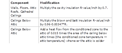
The compliance software user may specify quality insulation installation (QII) for the proposed design as “yes” or “no.” The effective R-value of cavity insulation is reduced, as shown in Table 16 in buildings with no QII. When set to “no,” framed walls, ceilings, and floors are modeled with added winter heat flow between the conditioned zone and attic to represent construction cavities open to the attic. QII does not affect the performance of continuous sheathing in any construction.
PROPOSED DESIGN
The compliance software user may specify compliance with QII. The default is “no” for QII. This results in a 30% derating applied to the cavity insulation.
STANDARD DESIGN
The standard design is modeled with “yes” for verified QII for newly constructed multifamily buildings and additions greater than 700 square feet in Climate Zones 1-6 and 8-16 (Climate Zone 7 has no QII for multifamily buildings). This results in the removal of the 30% derating to the cavity insulation.
VERIFICATION AND REPORTING
The presence of QII is reported in the HERS required verification listings on the LMCC. Verified QII is certified by the installer and field verified to comply with RA3.5. Credit for verified QII applies to ceilings/attics, knee walls, exterior walls, and exterior floors.
For alterations to existing pre-1978 construction, if the existing wall construction is assumed to have no insulation, no wall degradation is assumed for the existing wall.
Table 20: Modeling Rules for Unverified Insulation Installation Quality
Source: California Energy Commission