There are four energy saving measures associated with commercial kitchen ventilation. The origin of these proposed measures is found in recent amendments to ASHRAE 90.1 titled 90.1ax. Some details of these proposed measures deviate slightly from the measures found in 90.1ax.
The four measures address the following issues:
•Direct Replacement of Exhaust Air Limitations
•Type I Exhaust Hood Airflow Limitations
•Makeup and Transfer Air Requirements
•Commercial Kitchen System Efficiency Options
All four of these are Prescriptive Measures
There are no mandatory measures specific to commercial kitchens. The equipment efficiencies in §110.1 and §110.2 apply.
A. Kitchen Exhaust Systems §140.9(b)1
This section addresses kitchen exhaust systems. There are two requirements for kitchen exhaust:
•A limitation on use of short-circuit hoods §140.9(b)1A, and
•Maximum exhaust ratings for Type I kitchen hoods §140.9(b)1B
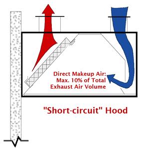
Limitation of Short-Circuit Hoods §140.9(b)1A
Short-circuit hoods are limited to ≤10% replacement air as a percentage of hood exhaust airflow rate. The reasons for this include the following:
Studies by PG&E, the AGA and the CEC have shown direct supply greater than 10% of hood exhaust in short-circuit hoods significantly reduces capture and containment. This only means that it reduces the extraction of cooking heat and smoke from kitchen.
As a result of this poor performance facilities increase the exhaust on these hoods which results in higher fan energy and conditioning of the make-up air.
Maximum Exhaust Ratings for Type I Kitchen Hoods §140.9(b)1B
The standards also limit the amount of exhaust for Type I kitchen hoods based on limits in Table 140.9-A. Similar to the discussion under short-circuit hoods, excessive exhaust increases but fan energy (supply and exhaust) and increases energy for conditioning of the make-up air. These restrictions are triggered where the total exhaust airflow for Type I and II hoods ≥5,000 cfm. There are two exceptions for this requirement:
Exception 1 to 140.9(b)1B: where ≥75% of the total Type I and II exhaust make-up air is transfer air that would otherwise have been exhausted. This exception could be used when you have a large dining area adjacent to the kitchen, which would be exhausting air for ventilation purposes even if the hoods were not running. If the air that would otherwise have been exhausted from the dining area (to meet ventilation requirements) is greater than 75 percent of the hood exhaust rate and is transferred to the kitchen for use as hood makeup than the exception is satisfied.
Exception 2 to 140.9(b)1B: for existing hoods that aren’t being replaced as part of an addition or alteration.
The values in Table 140.9-A are based on the type of hood (left column) and the rating of the equipment that it serves (columns 2 through 5). The values in this table are typically below the minimum airflow rates for unlisted hoods. They are supported by ASHRAE research for use with 'listed hoods (RP-12002). To comply with this requirement, the facility will likely has to use 'listed hoods. The threshold of 5,000 cfm of total exhaust was put in to exempt small restaurants but include larger restaurants and commercial/institutional kitchens.
The definitions for the types of hoods and the duty of cooking equipment are provided in ASHRAE Standard 154-2011.
|
Type of Hood |
Light Duty Equipment |
Medium Duty Equipment |
Heavy Duty Equipment |
Extra Heavy Duty Equipment |
|
Wall-mounted Canopy |
140 |
210 |
280 |
385 |
|
Single Island |
280 |
350 |
420 |
490 |
|
Double Island |
175 |
210 |
280 |
385 |
|
Eyebrow |
175 |
175 |
Not Allowed |
Not Allowed |
|
Backshelf/Pass-over |
210 |
210 |
280 |
Not Allowed |
B. Kitchen Ventilation §140.9(b)2
This section covers two requirements:
•Limitations to the Amount of Mechanically Heated or Cooled Airflow for Kitchen Hood Make-Up Air §140.9(b)2A
•Additional Efficiency Measures for Large Kitchens §140.9(b)2B
For both of these requirements it is important to know the terms, Mechanical Heating and Mechanical Cooling. The standard defines Mechanical Heating and Mechanical Cooling in §100.1 as follows:
Mechanical Cooling is lowering the temperature within a space using refrigerant compressors or absorbers, desiccant dehumidifiers, or other systems that require energy from depletable sources to directly condition the space. In nonresidential, high-rise residential, and hotel/motel buildings, cooling of a space by direct or indirect evaporation of water alone is not considered mechanical cooling.
Mechanical Heating is raising the temperature within a space using electric resistance heaters, fossil fuel burners, heat pumps, or other systems that require energy from depletable sources to directly condition the space.
An important part of the definition for Mechanical Cooling is the exclusion of direct and indirect evaporative cooling. The use of evaporative cooling for kitchen hood make-up air is unrestricted.
Limitations to the Amount of Mechanically Heated or Cooled Airflow for Kitchens §140.9(b)2A
This section limits the amount of mechanically cooled or heated airflow to any space with a kitchen hood. The amount of mechanically cooled or heated airflow is limited to the greater of:
•The supply flow required to meet the space heating or cooling load, or
•The hood exhaust minus the available transfer air from adjacent spaces.
The supply flow required to meet the space heating or cooling loads can be directly documented by providing the load calculations.
The calculation of the hood exhaust minus the available transfer air from adjacent spaces is a little more complex. It requires documenting the "available transfer air" from adjacent spaces which is defined in §140.9(b)2Aii as ," that portion of outdoor ventilation air serving adjacent spaces not required to satisfy other exhaust needs, such as restrooms, not required to maintain pressurization of adjacent spaces, and that would otherwise be relieved from the building." The process to calculate the available transfer air is as follows:
1. Calculate the minimum OSA requirements for the spaces that are adjacent to the kitchen.
2. Subtract the amount of air used by exhaust fans in the adjacent spaces. These include toilet exhaust and any hood exhaust in adjacent spaces.
3. Subtract the amount of air needed for space pressurization.
4. The remaining air is available for transfer to the hoods.
An exception is provided for existing kitchen make-up air units that are not being replaced as part of an addition or alternation.
While the requirement to use available transfer air only refers to "adjacent spaces", available transfer air can in fact come from any space in the same building as the kitchen. A kitchen in the ground floor of a large office building, for example, can draw replacement air from the return plenum and the return shaft. The entire minimum OSA requirement for the building, minus the other exhaust and pressurization needs, is available transfer air. If the return air path connecting the kitchen to the rest of the building is constricted, resulting in high transfer air velocities, then it may be necessary to install a transfer fan to assist the available transfer air in making its way to the kitchen. The energy use of such a transfer fan is quite small when compared to the extra mechanical heating and cooling energy to condition an equivalent amount of outside air year round.
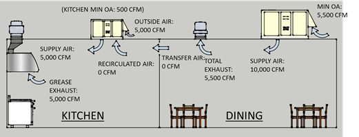
Example 10-1
Question
What is the available transfer air for the kitchen make up in the scenario shown in the following figure:
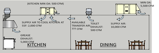
Answer
5,000 cfm calculated as follows.
The OSA supplied to the dining room is 5,500 cfm. From this we subtract 500 cfm for the toilet exhaust and 0 cfm for building pressurization. The remainder 5,500 cfm – 500 cfm – 0 cfm = 5,000 cfm of available transfer air.
Example 10-2
Question
Assuming that this kitchen needs 2,000 cfm of supply air to cool the kitchen with a design supply air temperature of 55°F, would the following design airflow meet the requirements of §140.9(b)2A?
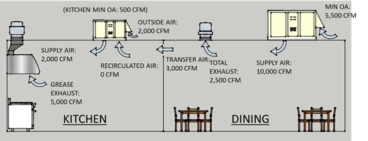
Answer
Yes. This example meets the first provision of §140.9(b)2A. The supply flow required to meet the cooling load is 2,000 cfm. Thus up to 2,000 cfm of mechanically conditioned make up air can be provided to the kitchen. Note that the supply from the make-up air unit, 2,000 cfm, is not as large as the hood exhaust, 5,000 cfm. This means that the remainder of the make-up air, 3,000 cfm, must be transferred from the dining room space.
Although this is allowed under §140.9(b)2Ai, this is not the most efficient way to condition this kitchen as demonstrated in the next example.
Example 10-3
Question
Continuing with the same layout as the previous example, would the following design airflow meet the requirements of §140.9(b)2A?
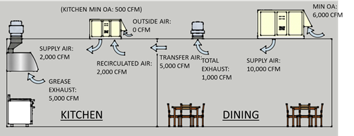
Answer
Yes. In this example 100% of the make-up air, 5,000 cfm, is provided by transfer air from the adjacent dining room. Note that the OSA on the unit serving the dining room has been increased to 6,000 cfm to serve the ventilation for both the dining room and kitchen. Since the dining room has no sources of undesirable contaminants we can ventilate the kitchen with the transfer air.
Comparing this image to the previous example you will see that this design is more efficient for the following reasons.
•The total outside airflow to be conditioned has been reduced from 7,500 cfm in the previous example (2,000 cfm at the MUA unit and 5,500 cfm at the dining room unit) to 6,000 cfm. And,
The dining room exhaust fan has dropped from 2,500 cfm to 1,000 cfm reducing both fan energy and first cost of the fan.
Note that an even more efficient design would be if the kitchen MAU unit had a modulating OA damper that allowed it to provide up to 5,000 CFM of outside air directly to the kitchen when OAT <kitchen space temperature. When OAT > space temperature then the OA damper on the MAU unit is shut and replacement/ventilation air is transferred from the dining area. This design requires a variable speed dining room exhaust fan controlled to maintain slight positive pressure in the dining area. This design is the baseline design modeled in the ACM modeling rules for performance compliance. Furthermore, the baseline model assumes that transfer air is available from the entire building, not just the adjacent spaces.
•
Example 10-4
Question
Continuing with the same layout as the previous examples, would the following design airflow meet the requirements of §140.9(b)2A?
Answer
No if the kitchen unit is mechanically heated or cooled. Per §140.9(b)2A the maximum amount of air that can be mechanically heated or cooled must be less than either:
1. Per §140.9(b)2Ai: 2,000 cfm, the supply needed to cool the kitchen (from Example 10-2)
2. Per §140.9(b)2Aii: 0 cfm, the amount of hood exhaust (5,000 cfm) minus the available transfer air (also 5,000 cfm from Example 10-2).
Additional Efficiency Measures for Large Kitchens §140.9(b)2B
For kitchens or dining facilities that have ≥5,000 cfm of Type I or II hood exhaust, the mechanical system must meet one of the following requirements:
1. Transfer air for make-up ≥50% of the total hood exhaust, or
2. Demand ventilation control on at least 75% of the exhaust air, or
3. 'Listed energy recovery devices with a sensible heat recovery effectiveness ≥40% on ≥50% of the total exhaust flow, or
4. ≥70% of the makeup air volume that is:
a. Unheated or heated to no more than 60°F, and
b. Uncooled or cooled without the use of mechanical cooling.
Transfer Air: There is an exception for existing hoods not being replaced as part of an addition or alteration.
The concept of transfer air was addressed in the discussion of §140.9(b)2A above.
Demand Ventilation Control: Per §140.9(b)2Bii Demand ventilation controls must have all of the following characteristics:
•Include controls necessary to modulate airflow in response to appliance operation and to maintain full capture and containment of smoke, effluent and combustion products during cooking and idle; and
•Include failsafe controls that result in full flow upon cooking sensor failure; and
•Include an adjustable timed override to allow occupants the ability to temporarily override the system to full flow; and
•Be capable of reducing exhaust and replacement air system airflow rates to the larger of:
o 50% of the total design exhaust and replacement air system airflow rates; or
o The ventilation rate required per Section 120.1.
There are several off the shelf technologies that use smoke detectors that can comply with all of these requirements.
Energy Recovery: Energy recovery is provided using air to air heat exchangers between the unit providing make-up air and the hood exhaust. This option is most effective for extreme climates (either hot or cold). It is not commonly used in the mild climates of California.
Tempered Air with Evaporative Cooling: The final option is to control the heating (if there is heating) to a space temperature setpoint of 60°F and to use evaporative (non-compressor) cooling or no cooling at all for most of the makeup air.
C. Kitchen Exhaust Acceptance §140.9(b)3
Acceptance tests for these measures are detailed in NA7.11. See Chapter 13 of this manual.
The application of these measures to additions and alterations was presented in the text from the previous section.
NRCC-PRC-03-E for Commercial Kitchen Requirements
This Compliance Documentation includes requirements details and system details of the space applicable under Commercial Kitchens by the 2013 Standards. Each kitchen location should be identified by a tag, relevant system details and reference to plans.
Project Description
PROJECT NAME is the title of the project, as shown on the plans and known to the enforcement agency.
DATE PREPARED is the last revision date of the plans. If the plans are revised after this date, it may be necessary to re-submit the compliance documentation to reflect the altered design. Note that it is the enforcement agency’s discretion whether or not to require new compliance documentation.
Total Installed Cooling Capacity
This section covers the PRESCRIPTIVE MEASURES installed in Commercial Kitchens including exhaust and ventilation systems.
Documentation Author’s Declaration Statement
The CERTIFICATE of COMPLIANCE – Commercial Kitchens Requirements is signed by both the Documentation Author and the Principal Designer who is responsible for preparation of the plans of building. This latter person is also responsible for this compliance documentation, even if the actual work is delegated to a different person acting as Documentation Author. It is necessary that the compliance documentation be consistent with the plans.
DOCUMENTATION AUTHOR is the person who prepared the compliance forms and who signs the Declaration Statement. The person’s telephone number is given to facilitate response to any questions that arise. A Documentation Author may have additional certifications such as an Energy Analyst or a Certified Energy Plans Examiner certification number. Enter number in the EA# or CEPE# box.
Principal Designer’s Declaration Statement
The Declaration Statement is signed by the person responsible for preparation of the plans for the building. This principal designer is also responsible for this compliance form, even if the actual work is delegated to someone else (the Documentation Author as described above). It is necessary that the compliance documentation be consistent with the plans. The Business and Professions Code governs who is qualified to prepare plans and therefore to sign this statement. See Section 2.2.2 Permit Application for applicable text from the Business and Professions Code.