…including elastomeric coatings and white acrylic coatings that qualify for Field Applied Liquid Coatings. The Standards specify minimum performance and durability requirements for field-applied liquid coatings. Please note that these requirements do not apply to industrial coatings that are factory-applied, such as metal roof panels. The requirements address elongation, tensile strength, permeance, and accelerated weathering. The requirements depend on the type of coating and are described in greater detail below. Liquid roof coatings applied to low-sloped roofs in the field as the top surface of a roof covering shall comply with the following mandatory requirements and descriptions.
Aluminum-pigmented coatings are silver-colored coatings that are commonly applied to modified bitumen and other roofing products. The coating has aluminum pigments that float to the top surface of the coating while it is setting, providing a shiny and reflective surface. Because of the shiny surface and the physical properties of aluminum, these coatings have a thermal emittance below 0.75, which is the minimum rating for prescriptive compliance.
This class of field-applied liquid coatings shall be applied across the entire surface of the roof and meet the dry mil thickness or coverage recommended by the coating manufacturer, taking into consideration the substrate on which the coating will be applied to. Also, the aluminum-pigmented asphalt roof coatings shall be manufactured in accordance with ASTM D2824. Standard Specification is also required for Aluminum-Pigmented Asphalt Roof Coatings, Nonfibered, Asbestos Fibered, and Fibered without Asbestos that are suitable for application to roofing or masonry surfaces by brush or spray. Use ASTM D6848, Standard Specification for Aluminum Pigmented Emulsified Asphalt used as a Protective Coating for Roofing; installed in accordance with ASTM D3805, Standard Guide for Application of Aluminum-Pigmented Asphalt Roof Coatings.
This class of coatings consists of a layer of cement and has been used for a number of years in the central valley of California and in other regions. These coatings may be applied to almost any type of roofing product.
Cement-based coatings shall be applied across the entire roof surface to meet the dry mil thickness or coverage recommended by the manufacturer. Also, cement-based coatings shall be manufactured to contain no less than 20% Portland Cement and meet the requirements of ASTM D822, ASTM C1583 and ASTM D5870.
Other field-applied liquid coatings include elastomeric and acrylic-based coatings. These coatings must be applied across the entire surface of the roof surface to meet the dry mil thickness or coverage recommended by the coating manufacturer, taking into consideration the substrate on which the coating will be applied. The field-applied liquid coatings must be tested to meet a number of performance and durability requirements as specified in Table 110.8-C of the Standards or the minimum performance requirements of ASTM C836, D3468, D6083, or D6694, whichever are appropriate to the coating material.
The radiant barrier is a reflective material that reduces radiant heat transfer caused by solar heat gain in the roof. Radiant barriers are installed below the roof deck in the attic and reduce radiant heat to air distribution ducts and insulation located below the radiant barrier. To qualify, a radiant barrier must have an emittance of 0.05 or less. The product must be tested according to ASTM C-1371-98 or ASTM E408-71(2002) and must be certified by the California Bureau of Electronic and Appliance Repair, Home Furnishings and Thermal Insulation and listed in their Consumer Guide and Directory of Certified Insulation material, at www.bhfti.ca.gov/industry/tinsulation.shtml.
§110.8(d), §110.8(e), §150.0(a), §150.0(b). These sections are also shown in Appendix B of this document.
Wood framed roof/ceiling construction assemblies must have at least R-30 insulation or a maximum U-factor of 0.031 based on 24 inch on center wood framed rafter roofs, as determined from the Reference Joint Appendix JA4. Some areas of the roof/ceiling can be less than the mandatory minimum U-factor as long as other areas exceed the requirement and the weighted average U-factor for the overall ceiling/roof is 0.031 or less.
Metal-framed and roof/ceiling constructions other than wood framed must have a U-factor of 0.031 or less in order to comply with the mandatory measures. If the insulation is not penetrated by framing, such as rigid insulation laid over a structural deck, then the rigid insulation can actually have a rated R-value of less than R-30 so long as the total roof/ceiling assembly U-factor is not greater than U-0.031.
Loose fill insulation must be blown in evenly, and insulation levels must be documented on the Certificate of Installation (CF2R). The insulation level can be verified by checking that the depth of insulation conforms to the manufacturer’s coverage chart for achieving the required R-value. The insulation must also meet the manufacturer’s specified minimum weight per ft² for the corresponding R-value. When installing loose fill insulation, the following guidelines should be followed:
For wood trusses that provide a flat ceiling and a sloped roof, the slope of the roof should be at about 4:12 or greater in order to provide adequate access for installing the insulation. Insulation thickness near the edge of the attic will be reduced with all standard trusses, but this is acceptable as long as the average thickness is adequate to meet the minimum insulation requirement.
If the ceiling is sloped (for instance, with scissor trusses), loose fill insulation can be used as long as the slope of the ceiling is no more than 4:12. If the ceiling slope is greater than 4:12, loose fill should be used only if the insulation manufacturer will certify the installation for the slope of the ceiling.
At the apex of the truss, a clearance of at least 30 inch should be provided to facilitate installation and inspection.
The mandatory measures have two requirements depending on frame size:
1. 2x4 inch wood-framed walls above grade shall have at least R-13 insulation installed in the cavities between framing members, or a U-factor that cannot exceed U-0.102. Insulation may be of greater insulating value in certain areas of the wall and of lesser insulating value in other areas of the wall provided that the area-weighted U- factor does not exceed 0.102 to show equivalence to an R-13 wall.
2. 2x6 inch or greater wood-framed walls above grade shall have at least R-19 insulation installed in the cavities between framing members or a U-factor not exceeding 0.074. Insulation may be of greater insulating value in certain areas of the wall and of lesser insulating value in other areas of the wall provided that the area-weighted U-factor does not exceed 0.074 to show equivalence to an R-19 wall.
There are several cases where the mandatory measures for wall insulation do not apply or apply in a special way. These include the following:
1. The mandatory measures apply to framed foundation walls of heated basements or heated crawl spaces that are located above grade, but not to the portion that is located below grade.
2. For additions to existing buildings, existing wood-framed walls that are already insulated with R-11 insulation need not comply with the mandatory R-13 wall insulation.
3. Rim joists between floors of a multi-story building are deemed to comply with these mandatory measures if they have R-13 insulation installed on the inside of the rim joist and are properly installed between joist members.
For demising partitions and knee walls are not required to meet the prescriptive requirements of §150.1(c)1B. Demising partitions and knee walls are required to meet the mandatory minimum insulation requirement as set in §150.0(c)1 and 2. §150.0(c)1 requires that insulation not less than R-13 be installed between a 2x4 framing, or a U-factor which shall not exceed U-0.102. §150.0(c)2 requires insulation not less than R-19 be installed in framing of 2x6 inch or greater, or a U-factor equal to or less than 0.074.
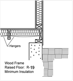
Wood-framed floors must have at least R-19 insulation installed between framing members, or the construction must have a U-factor of 0.049 or less. The equivalent U-factor is based on R-19 insulation in a wood-framed floor. The R-19 insulation value and U-factor of U-0.049 are for the floor assembly alone and do not assume the effects of a crawlspace or buffer zone beneath the floor. If comparing to a crawlspace assembly, the equivalent U-factor is 0.037, which includes the effect of the crawlspace.
Other types of raised floors, except for concrete raised floors (concrete raised floors do not have a mandatory requirement, but do have a prescriptive requirement) **need to meet, must also meet the maximum U-factor. In all cases, some areas of the floor can have a U-factor less than the requirement as long as other areas have a U-factor that exceeds the requirement and the area-weighted average U-factor is less than described above.
Raised slab floors with radiant heat (heated slab floors) must meet special insulation requirements that are described in Chapter 4 of this 'manual.
When a controlled ventilated crawlspace or an unvented crawlspace is used, raised-floor insulation is not required.
The Standards have mandatory requirements to limit infiltration associated with fireplaces, decorative gas appliances, and gas logs. Fireplace efficiency can be greatly improved through proper air control, and reduced infiltration is also a benefit when the fireplace is not operating (the majority of the time for most houses).
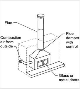
Installation of factory-built or masonry fireplaces (see Figure 3-16) must include the following:
1. Closable metal or glass doors covering the entire opening of the firebox,
2. Doors covering the entire opening of the firebox that can be closed when the fire is burning,
3. A combustion air intake that is at least 6 square inches to draw air from outdoors and equipped with a readily accessible, operable and tight-fitting damper or combustion air control device (Exception: An outside combustion air intake is not required if the fireplace is installed over a concrete slab and the fireplace is not located on an exterior wall),
4. A flue damper with a readily accessible control. (Exception: When a gas log, log lighter or decorative gas appliance is installed in a fireplace, the flue damper shall be blocked open if required by the manufacturer's installation instructions or the California Mechanical Code).
Continuous burning pilot lights are prohibited for fireplaces as well as for decorative gas appliances and gas logs. In 'addition, indoor air may not be used for cooling a firebox jacket when that indoor air is vented to the outside of the building.
When a gas log, log lighter or decorative gas appliance is installed in a fireplace, the flue damper must be blocked open if required by the manufacturer's installation instructions or the California Mechanical Code.
Example 3-14
Question
Are closable glass or metal doors required for decorative gas appliances?
Answer
Yes. Decorative gas appliances are required to have closable glass or metal doors covering the entire opening of the firebox.
Example 3-15
Question
If I want to have a gas log or some other device in the fireplace of my home, can I have a standing pilot light? Can I block open the damper?
Answer
The Standards disallow standing pilot light. The flue damper may be blocked open if required by either the manufacturer's installation instructions or the California Mechanical Code.
Example 3-16
Question
§150.0(e)2 states that no fireplace, decorative gas appliance or gas log can be installed if it has a
continuously burning pilot light. The California Mechanical Code requires all gas appliances installed in California to have a manually operated shut-off valve, accessible to the inhabited space. Does this shut-off valve meet the intent of this section?
Answer
Not if the pilot light must be manually extinguished when the appliance is off. A unit that meets the intent of this section will have a pilot light that cannot stay on when the unit is off.
Example 3-17
Question
A building plan specifies a freestanding gas heater that is decorative; however, the equipment is vented and is rated as a room heater. Is it acceptable that this appliance have a pilot light?
Answer
Yes. Since this equipment is rated as a room heater, it can have a continuous burning pilot light.
Example 3-18
Question
Do decorative gas appliances need glass or metal doors?
Answer
Yes, the door requirement applies to masonry or factory-built fireplaces only. If a decorative gas appliance is installed inside a fireplace, the fireplace needs doors. Consult with the manufacturer of the decorative gas appliance regarding combustion air requirements.
Luminaires recessed in insulated ceilings can create thermal bridging through the insulation. Not only does this degrade the performance of the ceiling assembly, but it can also permit condensation on a cold surface of the luminaire if exposed to moist air, as in a bathroom.
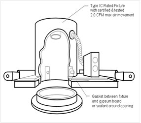
For these reasons, luminaires recessed in insulated ceilings must meet three requirements:
1. They must be listed as defined in the Article 100 of the California Electric Code for zero clearance insulation contact (IC) by Underwriters Laboratories or other testing/rating laboratories recognized by the International Conference of Building Officials. This enables insulation to be in direct contact with the luminaire.
2. The luminaire must have a label certified as per §150.0(k)8B for air tight (AT) construction. Air tight construction means that leakage through the luminaire will not exceed 2.0 cfm when exposed to a 75 Pa pressure difference, when tested in accordance with ASTM E283.
3. The luminaire must be sealed with a gasket or caulk between the housing and ceiling.
Refer to the Lighting chapter (chapter 6) of this compliance 'manual for more information regarding the applicable requirements for recessed luminaires.
§150.0(l) §118(g)
Mandatory measures require that the insulation material must be suitable for the application, with a water absorption rate no greater than 0.3 percent when tested in accordance with ASTM C272 Test Method A, 24-Hour-Immersion, and a vapor permeance no greater than 2.0 perm/inch when tested in accordance with ASTM E96. An example of an insulating material that meets these specifications is smooth-skin extruded polystyrene.
The insulation must also be protected from physical and UV degradation by either installing a water-resistant protection board, extending sheet metal flashing below grade, choosing an insulation product that has a hard durable surface on one side, or by other suitable means.
All buildings shall meet the requirements of ASHRAE Standard 62.2, Ventilation and Acceptable Indoor Air Quality in Low-Residential Buildings. The whole-building ventilation airflow shall be provided to meet the requirements of ASHRAE 62.2. Window operations are not a permissible method of providing whole house ventilation. Use of a continuously operating central fan integrated with a forced-air system air handler cannot be used to meet the whole-building ventilation airflow requirement.
ASHRAE Standard 62.2 requires ventilation openings in habitable spaces, toilets and utility rooms. Spaces that meet the exhaust requirements are exempted from meeting the whole-building ventilation air flow requirement; there for an exhaust system can be substituted for a ventilation opening (see Section 4.6.6).
Field Verification and Diagnostic Testing
Field verification and diagnostic testing is required to confirm proper ventilation airflow following the procedures specified in the Residential Reference Appendices, Appendix RA3.7.
Example 3-19 – Ventilation Opening Louvers
Question
There are fixed wooden louvers over a window in a bedroom. The louvers have slats that are 1/8 inch thick, and they are spaced 1 inch apart. What is the reduction in square inches of openable area?
Answer
Assuming a window of 4 x 5 feet with 1 inch spacing between 1 inch louvers. Each louver has a space of 1 inch measured perpendicular to the slats (the correct way). The reduction is the slat thickness divided by the spacing, or 1/8 inch. The opening area is the original opening area (2880in2) x ((1in – 1/8in)/1in) = 2520in2.
§150.0(g) and Reference Residential Appendix RA4.5.2
Vapor retarder class is a measure of the ability of a material or assembly to limit the amount of moisture the passes through the material or assembly. Vapor retarder classes are defined in Section 202 of the CBC. Testing for vapor retarder class is defined using the desiccant method of ASTM E96.
1. Class I: 0.1 perm or less
2. Class II: 0.1 < perm < 1.0 perm
3. Class III: 1.0 < perm < 10 perm
In climate zones 14 and 16, a continuous Class II vapor retarder, lapped or joint sealed, must be installed on the conditioned space side of all insulation in all exterior walls, on the floors of vented attics, and in unvented attics with air-permeable insulation.
Buildings with unvented crawl spaces in Climates zones 1-16 must have a Class I or Class II vapor retarder covering the earth floor to protect against moisture condensation.
If a building has a controlled ventilation crawl space a Class I or Class II vapor retarder must be placed over the earth floor of the crawl space to reduce moisture entry and protect insulation from condensation in accordance with Reference Residential Appendix RA4.5.2.
There are many product types having tested vapor retarder performance. Some common examples are:
1. Foil and other facings on gypboard can provide moisture resistance and product literature should always be checked to ensure conformance to ASTM E96.
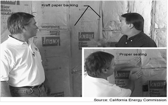
2. The kraft paper used as facing on thermal batt insulation material is typically a Class II vapor retarder. Faced-batts may or may not have flanges for fastening to assembly framing. Fastening flanges may be face or inset stapled or not stapled at all as the flanges provide no moisture control. Face stapling of flanged thermal batts helps ensure the insulation material is installed fully and properly within the framed cavity. Flangeless batts are also common and require no fastening as these materials maintain their installation integrity through friction-fitting within the cavity of framed assemblies. In all cases, the insulation must be installed properly.
3. Many interior painted surfaces may also qualify for meeting the vapor retarder requirement if the paint product has been tested to show its compliance as a vapor retarder. The effectiveness of vapor retarder paint is dependent on the installed thickness, in mils. These products often require more than one layer to achieve their tested perm rating and care must be shown by the installer of the paint and for inspection by the building official.
For all types of vapor barriers, care should be taken to seal penetrations such as electric outlets on exterior walls.

A. Roof/Ceiling
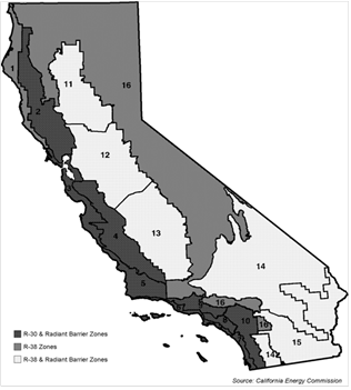
The prescriptive package, Component Package A, compliance method requires R-38 insulation or a U-factor of 0.025 in climate zones 1, and 11 through 16. R-30 insulation or U-factor of 0.031 is required in all other climate zones. In 'addition, a radiant barrier is required in climate zones 2 through 15; the climate zones where air conditioning is more common.
There are three ways to meet the prescriptive insulation requirement. The first way is to install R-30 or R-38 attic insulation in wood-framed construction. Wood-framed constructions include those in Tables 4.2.1 and 4.2.2 in Reference Joint Appendix JA4.
The second way is to use a different roof assembly from Reference Joint Appendix JA4, including structural insulated panel systems (SIPS) or metal-framed roofs, as long as they have a U-factor less than that of a wood-framed attic (the choices from Table 4.2.1 in Reference Joint Appendix JA4). The U-factor criteria are 0.025 (Table 4.2.1, cell entry A21) in climate zones 1 and 11 through 16 (where R-38 is required) and 0.031 (Table 4.2.1, cell entry A20) in the other climate zones (where R-30 is required).
The third way is to use the Energy Commission’s EZ-Frame assembly calculator to calculate the U-factor of the assembly components intended for the building design than those listed for Reference Joint Appendix JA4. The EZ-Frame assembly calculator can be used to calculate the total overall R-value and assembly’s U-factor. EZ-Frame is based on procedures of ASHRAE Handbook of Fundamentals.
Note that R-30 or R-38 installed in a wood rafter construction (the choices from JA4 Table 4.2.2) are acceptable for complying with Component Package A, since they have the minimum required insulation, even though these have a U-factor higher than the U-factor criteria stated above.
Construction Practice/Compliance and Enforcement
Insulation coverage should extend far enough to the outside walls to cover the bottom chord of the truss. However, insulation should not block eave vents in attics because the flow of air through the attic space helps remove moisture that can build up in the attic and condense on the underside of the roof. This can cause structural damage and reduce the insulation’s effectiveness.
Insulation may be tapered near the eave, but it must be applied at a rate to cover the entire ceiling at the specified level. An elevated truss is not required but may be desirable. See the Advanced Assembly section.
B. Radiant Barriers
The prescriptive requirements call for a radiant barrier in climate zones 2 through 15. The radiant barrier is a reflective material that reduces radiant heat transfer caused by solar heat gain in the roof. Radiant barriers reduce the radiant gain to air distribution ducts and insulation located below the radiant barrier, typically within the attic space. In the performance approach, radiant barriers are modeled as separate adjustments to the heating U-factor and the cooling U-factor. The duct efficiency is also affected by the presence of a radiant barrier when using the performance approach.
Radiant Barrier Construction Practice
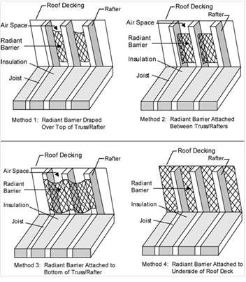
The most common way of meeting the radiant barrier requirement is to use roof sheathing that has a radiant barrier bonded to it by the manufacturer. Some oriented strand board (OSB) products have a factory-applied radiant barrier. The sheathing is installed with the radiant barrier (shiny side) facing down toward the attic space. Alternatively, a radiant barrier material that meets the same ASTM test and moisture perforation requirements that apply to factory-laminated foil can be field-laminated. Field lamination must use a secure mechanical means of holding the foil type material to the bottom of the roof decking such as staples or nails that do not penetrate all the way through the roof deck material. Roofs with gable ends must have a radiant barrier installed on them to meet the radiant barrier requirement.
Other acceptable methods are to drape a foil type radiant barrier over the top of the top chords before the sheathing is installed, stapling the radiant barrier between the top chords after the sheathing is installed, and stapling the radiant barrier to the underside of the truss/rafters (top chord). For these installation methods, the foil must be installed with spacing requirements as described in Residential Reference Appendices RA4.2.1. Installation of radiant barriers is somewhat more challenging in the case of closed rafter spaces, particularly when roof sheathing is installed that does not include a laminated foil type radiant barrier. Radiant barrier foil material may be field-laminated after the sheathing has been installed by “laminating” the foil as described above to the roof sheathing between framing members. This construction type is described in the Residential Reference Appendices RA4.2.1.1. See below for drawings of radiant barrier installation methods.
C. Roofing Products (Cool Roof)
Cool roofs of steep and low-sloped roofs are required in some climate zones. A low-slope roof is defined as a surface with a pitch less than or equal to 2:12 (9.5 degrees from the horizontal or less) while a steep-slope roof is a surface with a pitch greater than 2:12 (more than 9.5 degrees from the horizontal). The prescriptive requirement is based on an aged solar reflectance and thermal emittance tested value from the CRRC.
An alternative to the aged solar reflectance and thermal emittance is to use the Solar Reflectance Index (SRI) to show compliance. A calculator has been produced to calculate the SRI by designating the Solar Reflectance and Thermal emittance of the desired roofing material. The calculator can be found at www.energy.ca.gov/title24/2013standards. To calculate the SRI, the 3-year aged value of the roofing product must be used. By using the SRI calculator a cool roof may comply with an emittance lower than 0.85, as long as the aged reflectance is higher and vice versa.
The residential roofing product requirement in the prescriptive package is as follows. For steep-sloped applications in climate zones 10-15, the three year aged solar reflectance requirement of 0.20 and a (three year aged or initial) thermal emittance requirement of 0.75, or a minimum solar reflectance index (SRI) of 16.
For low-sloped roofing applications, in climate zones 13 and 15, there is a minimum aged solar reflectance of 0.63 and thermal emittance of 0.75, or a minimum SRI of 75.
There are two exceptions to meeting the roofing products requirements in the prescriptive package:
1. The roof area with building integrated photovoltaic panels and building integrated solar thermal panels are exempt from the minimum requirements for aged solar reflectance and thermal emittance or SRI Exception 1 to §150.1(c)11B.
2. Roof constructions that have thermal mass over the roof membrane with a weight of at least 25 lb/ft² are exempt from the minimum requirements for aged solar reflectance and thermal emittance or SRI under Exception 2 to §150.1(c)11B.
Construction Practice/Compliance and Enforcement
The compliance and enforcement process should ensure that the cool roof efficiency values (solar reflectance and thermal emittance values) modeled on the CF1R form are specified on the building plans, and that those same values of the actual installed cool roof product meet or exceed the efficiency values on the CF1R form. For more information on Compliance and Enforcement on cool roof, see chapter 2 of this 'manual.
Example 3-20
Question
A computer method analysis shows that a new house requires R-19 ceiling insulation to comply using the performance approach, but the minimum mandatory insulation level for ceiling insulation is only R-30. Which insulation level should be used?
Answer
R-30 the higher insulation level must be installed for the building to comply. In some cases such as this, minimum mandatory measures are superseded by stricter compliance measures when using the performance approach.
Example 3-21
Question
A small addition to an existing house appears to comply using only R-15 ceiling insulation with the performance approach. Does this insulation level comply with the Standards?
Answer
No. R-15 would not be sufficient because the required minimum ceiling insulation level established by the mandatory measures is R-30. However, R-15 could be used in limited areas, as follows:
1. 16-inches on center framing with attic with the weighted average U-factor for the entire ceiling/roof less than 0.032.
2. 24-inches on center framing with attic with the weighted average U-factor for the entire ceiling/roof less than 0.031
3. 16-inches on center rafter without attic with the weighted average U-factor for the entire ceiling/roof less than 0.051.
4. 24-inches on center rafter without attic with the weighted average U-factor for the entire ceiling/roof less than 0.049.
D. Wall Insulation
1. Framed Walls
The Package A prescriptive requirements (Standards Table 150.1-A call for either R-15 cavity wall insulation with R-4 continuous insulation or R-13 cavity wall insulation with R-5 continuous insulation with 2x4 framing or a U-factor of 0.065 in all climate zones.
Wood-framed walls may comply by specifying and installing the minimum R-value indicated. For metal-framed walls, or as an alternative to meeting the installed R-value in wood-framed walls, the designer may choose any wall construction from Reference Joint Appendix JA4 that has a U-factor equal to or less than 0.065).
Metal-framed assemblies will require rigid insulation in order to meet the maximum U- factor criteria. U-factors for metal-framed walls are given in Reference Joint Appendix JA4.
Demising partitions and knee walls are not required to meet the prescriptive requirements of §150.1(c)1B. Demising partitions and knee walls are required to meet the mandatory minimum insulation requirement as set in §150.0(c)1 and 2 requires that insulation not less than R-13 be installed between a 2x4 framing, or a U-factor which shall not exceed U-0.102. §150.0(c)2 requires insulation not less than R-19 be installed in framing of 2x6 inch or greater, or a U-factor equal to or less than 0.074.
2. Mass Walls
§150.1(c) These sections are also shown in Appendix B of this document.
The prescriptive requirements have separate criteria for mass walls with interior insulation and mass walls with exterior insulation. “Interior” denotes that insulation is installed on the interior surface of the mass wall and “exterior” denotes insulation is installed on the exterior surface of the mass wall. Placement of insulation on mass walls does affect the thermal mass properties of a building. The affect of thermal mass helps temper the fluctuation of heating and cooling loads throughout the year in the building.
3. Concrete Mass and Furred Walls
To determine the total R-value of a mass wall, the U-factor from Reference Joint Appendix JA4 Table 4.3.5, 4.3.6 or other masonry tables is added to an insulation layer selected from Reference Joint Appendix JA4 Table 4.3.14. When the prescriptive requirements are used, the insulation must be installed integral with or on the exterior or interior of the mass wall.

The walls addressed in the Properties of Solid Unit Masonry and Solid Concrete Walls tables in the Reference Joint Appendix JA4 tables are rarely used in residential construction, but are common in some types of nonresidential construction. For residential construction, the Prescriptive CF1R, CF1R-ADD and CF1R-ALT can calculate complex wall systems to include furred strip walls.
A four step process is required to calculate the effective U-factor of a furred wall;
1. Select one of the concrete or masonry walls tables and select a U-factor; and
2. Select the appropriate Effective R-value for Interior or Exterior Insulation Layers in Table 4.3.14; and
3. Fill out the CF1R Insulation Values for Opaque Surface table columns. To achieve the Proposed Assembly U-factor or R-value column, first the Furring Strips Construction Table for Mass Walls Only table needs to be filled out; and
4. Calculate the Final Assembly R-value and carry the value back to the Insulation Values for Opaque Surface Details table. Compare the R-value, it must be equal to or greater than the mass standard R-value from Energy Standards Prescriptive TABLE 150.1-A.
Construction Practice/Compliance and Enforcement
The compliance and enforcement process should ensure that the insulation R-value for walls (cavity and/or continuous) modeled on the CF1R form is specified on the building plans and that the same value for the actual installed wall insulation meets or exceeds the R-value on the CF1R form. For more information on Compliance and Enforcement on wall insulation, see Chapter 2 of this 'manual.
Because it is difficult to inspect wall insulation behind tub/shower enclosures after the enclosures are installed, insulation of these wall sections should be inspected during the framing inspection.
Batt and loose fill insulation should fill the wall cavity evenly. If Kraft or foil-faced insulation is used, it should be installed per manufacturer recommendations to minimize air leakage and avoid sagging of the insulation.
Wall insulation should extend into the perimeter floor joist (rim joist) cavities along the same plane as the wall.
If a vapor retarder is required, it must be installed on the conditioned space side of the framing.

Wood-Framed Wall with Brick Veneer, Mandatory Minimum R-13
Insulation
Source: California Energy
Commission

Wood-Framed Wall with Vinyl or Aluminum Siding, Mandatory Minimum
R-13 Insulation
Source: California Energy
Commission
Example 3-22
Question
Do new residential buildings or additions consisting of block walls (for example, converting a garage into living space) have to comply with the R-13 minimum wall insulation requirement? If not, what insulation R-value do they need?
Answer
Framed walls must meet the R-13 requirement or the U-factor associated with it. There is no mandatory minimum insulation requirement for mass walls. However, there are minimum insulation requirements in Package A for both framed and mass walls that must be met under Prescriptive compliance.
Example 3-23
Question
If 2-inches of medium density foam is used in combination with R-13 batt insulation in the cavity of a 2x6 wood framed wall, without continuous insulation added, what is the total U-factor for the wall assembly? Does this assembly meet prescriptive compliance Package A requirements?
Answer
No. Medium density foam is given a default value of R-5.8 per inch. When added with R-11 batt insulation, the total cavity insulation is R-22. The Reference Joint Appendix JA4 Table 4.3.1 shows the wall U-factor for this assembly as 0.072 (cell entry A7). The assembly does meet the minimum mandatory wall insulation U-factor requirement of 0.110, but does not meet the prescriptive compliance Package A U-factor requirement of 0.065. To meet the Package A requirement, Advanced Wall System (AWS) techniques may be used to reduce the framing factor, or continuous insulation may be added.
E. Floor Insulation
1. Raised-floor
Package A prescriptive requirements call for R-19 or maximum U-factor of 0.037 insulation in raised floors in all climates.
The requirement may be satisfied by installing the specified amount of insulation in a wood-framed floor or by meeting an equivalent U-factor. U-factors for raised-floors are listed in Reference Joint Appendix JA4. Concrete floors separating multifamily habitable space from a parking garage are also considered a raised-floor. For this class of construction, R-4 insulation is required for climate zones 12 and 15, and R-8 is required for climate zones 1, 2, 11, 13, 14, and 16. No insulation is required in other climate zones with a concrete raised floor.
|
Insulation R-value |
Crawlspace? |
Reference Joint Appendix JA4 Construction and Table Cell Entry |
Equivalent U-factor |
|
R-19 |
No |
4.4.2 A4 |
0.049 |
|
R-19 |
Yes |
4.4.1 A4 |
0.037 |
Construction Practice/Compliance and Enforcement
Floor insulation should be installed in direct contact with the subfloor so that there is no air space between the insulation and the floor. Support is needed to prevent the insulation from falling, sagging, or deteriorating.
Options for support include netting stapled to the underside of floor joists, insulation hangers running perpendicular to the joists, or other suitable means. Insulation hangers should be spaced at 18 inch or less prior to rolling out the insulation. Insulation hangers are heavy wires up to 48 inch long with pointed ends, which provide positive wood penetration. Netting or mesh should be nailed or stapled to the underside of the joists. Floor insulation should not cover foundation vents.
2. Slab Insulation
Prescriptive Table 150.1-A, Package A, requires slab insulation only in climate zone 16. In this case, a minimum of R-7 must be installed. The insulation must be installed to a minimum depth of 16 in. or to the bottom of the footing, whichever is less. The depth is measured from the top of the insulation, as near the top-of-slab as practical, to the bottom edge of the insulation (see ).
Perimeter insulation is not required along the slab edge between conditioned space and the concrete slab of an attached unconditioned enclosed space such as a garage, covered porch, or covered patio. Neither would it be practical or necessary to insulate concrete steps attached to the outside slab edge.
In situations where the slab is below grade and slab edge insulation is being applied to a basement or retaining wall, the top of the slab edge insulation should be placed as near to ground level as possible and extended down at least 16 inches. In situations where the slab is above grade and slab edge insulation is being applied, the top of the slab edge insulation should be placed at the top of the slab.
Construction Practice/Compliance and Enforcement
Slab-edge insulation should be protected from physical damage and ultraviolet light exposure because deterioration from moisture, pest infestation, ultraviolet light and other factors can significantly reduce the effectiveness of the insulation.
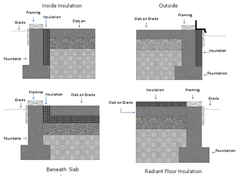
When slab-edge insulation is required by the prescriptive or
performance requirements, then minimum depth is 16 inch or to the top of the
footing, whichever is less.
Source: California Energy
Commission
Example 3-24
Question
What are the slab edge insulation requirements for a hydronic-heating system with the hot water pipes in the slab?
Answer
The requirements for insulation of heated slabs can be found in §110.8(g) of the Standards and are described in Chapter 4 of this 'manual. The material and installation specifications are as follows:
•Insulation values as shown in Table 110.8-A of the Standards
•Protection from physical damage and ultra-violet light deterioration
•Water absorption rate no greater than 0.3% (ASTM-C272)
•Water vapor permeance no greater than 2.0 perm/inch (ASTM-E96)