
This group of building descriptors relate to HVAC systems at the zone level. There is not a one-to-one relationship between HVAC components in the proposed design and the Standard Design since the Standard Design system is determined from building type, size, and heating source. The applicability of each building descriptor for each of the 11 Standard Design systems is indicated in tables under the building descriptor Standard Design rules. Additions and Alterations should follow the same requirements stated for new construction Proposed Designs and new construction Standard Designs; unless otherwise noted in the descriptor.
Space Thermostat Throttling Range
Applicability
All thermal zones
Definition
The number of degrees that the room temperature must change to cause the HVAC system to go from no heating or cooling (i.e., space temperatures floating) to full heating or cooling.
Units
Degrees Fahrenheit (°F)
Input Restrictions
The prescribed value is 2°F. (This is equivalent to a +/- 1F temperature tolerance around the heating and cooling setpoint.) No input is needed and the prescribed value may not be overridden.
Standard Design
Same as the proposed design
Space Temperature Schedule
Applicability
All thermal zones
Definition
An hourly space thermostat schedule
Units
Data structure: temperature schedule
Input Restrictions
Prescribed. The Schedule Group is specified for the given Space Type in Appendix 5.4A, and the schedule values are specified in Appendix 5.4B.
Standard Design
Schedules in the Standard Design shall be identical to the proposed design.
Applicability
All thermal zones
Definition
A terminal unit includes any device serving a zone (or group of zones collected in a thermal zone) that has the ability to reheat or recool in response to the zone thermostat. This includes:
•None (the case for single zone units)
•VAV box
•Series Fan-Powered VAV box
•Parallel Fan-Powered VAV box
•Induction-type VAV box
•Dual-duct mixing box (constant volume and VAV)
•Two and three duct mixing dampers (multi-zone systems)
•Reheat coil (constant volume systems)
•Perimeter induction units
Units
List (see above)
Input Restrictions
As designed
Standard Design
Table 14 specifies the HVAC terminal device for each of the Standard Design systems. See Section 5.1.2 for a summary of the HVAC mapping.
|
Standard Design System |
Terminal Type |
|
System 1 – PTAC |
None |
|
System 2 – FPFC |
None |
|
System 3 – PSZ-AC |
None |
|
System 5 – Packaged VAV with Reheat |
VAV Box |
|
System 6 – VAV with Reheat |
VAV Box |
|
System 7 – SZVAV |
None |
|
System 9 – Heating and Ventilation |
None |
|
System 10 – CRAH |
None |
|
System 11 – CRAC |
None |
|
System 12 – LAB |
None |
|
System 13 – Kitchen |
None |
This group of building descriptors applies to proposed design systems that have reheat coils at the zone level. The building descriptors are applicable for Standard Design systems 5 and 6.
Terminal Heat Type
Applicability
Systems that have reheat coils at the zone level
Definition
The heating source for the terminal unit. This includes:
•Electric resistance
•Gas furnace
•Oil furnace
•Hot water
•Steam
Units
List (see above)
Input Restrictions
As designed.
Standard Design
Table 15 shows the terminal heat type for each Standard Design system.
|
Baseline building System |
Terminal Heat Type |
|
System 1 – PTAC |
None |
|
System 2 – PTHP |
None |
|
System 3 – PSZ-AC |
None |
|
System 4 – PSZ-HP |
None |
|
System 5 – Packaged VAV with Reheat |
Hot Water |
|
System 6– VAV with Reheat |
Hot Water |
|
System 7 – SZVAV |
None |
|
System 8 – SZVAV HP |
None |
|
System 9 – Heating and Ventilation |
None |
|
System 10 – CRAH Unit |
None |
|
System 11 – CRAC Unit |
None |
|
System 12 – LAB |
None |
|
System 13 – Kitchen |
None |
Terminal Heat Capacity
Applicability
Systems that have reheat coils at the zone level
Definition
The heating capacity of the terminal heating source
Units
Btu/h
Input Restrictions
As designed. However, if the unmet load hours exceed 150, the energy analyst and design team may have to increase the size of the equipment so that the unmet load hours are less than 150. See Figure 10.
Standard Design
The software shall automatically size the terminal heating capacity to be 25% greater than the design loads. See Figure 2.
Reheat Delta T
Applicability
Systems that have reheat coils at the zone level
Definition
This is an alternate method to enter the terminal heat capacity. It can be calculated as follows:
(3)  ∆Treheat =
Treheat - Tcool_supply
∆Treheat =
Treheat - Tcool_supply
∆Treheat =
Qcoil / (1.1*CFM)
where
∆Treheat heat rise across the terminal unit heating coil (°F)
Treheat heating air temperature at design (°F)
Tcool_supply supply air temperature at the heating coil (°F)
Qcoil heating coil load (Btu/h)
CFM airflow (cfm)
Units
Degrees Fahrenheit (°F)
Input Restrictions
As designed, but may need to be increased if zone unmet load hours are greater than 150.
Standard Design
Method not used for standard design. (The temperature difference shall be no more than 40F.) See Heat Capacity above.
Baseboard Capacity
Applicability
All thermal zones
Definition
The total heating capacity of the baseboard unit(s)
Units
Btu/h
Input Restrictions
As designed
Standard Design
Not applicable to the standard design
Baseboard Heat Control
Applicability
All thermal zones
Definition
Defines the control scheme of base board heating as either:
•Controlled by a space thermostat
Units
List (see above)
Input Restrictions
Controlled by space thermostat is the only type allowed if baseboard heating is used.
Standard Design
Not applicable for the standard design
5.6.5.1 VAV Air Flow
This group of building descriptors applies to proposed design systems that vary the volume of air at the zone level. The building descriptors are applicable for standard design systems 5 and 6.
Design Airflow
Applicability
Systems that vary the volume of air at the zone level
Definition
The air delivery rate at design conditions
Units
cfm
Input Restrictions
As designed.
If the unmet load hours in the proposed design are greater than 150, the compliance simulation should not proceed and the user may have to modify the Design Airflow value manually.
Standard Design
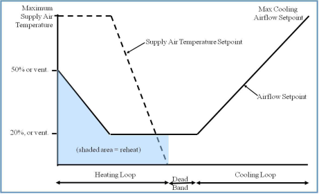
For systems 5 and 6, the software shall automatically size the system airflow to meet both: (a) the standard design peak cooling load based on a supply-air-to-room-air temperature difference of 20°F for exterior zones or 15°F for interior zones, the required ventilation air from Table 120.1-A of the Standard, or makeup air; whichever is greater and (b) the standard design peak heating load based on 50% zone flow and 95F supply air temperature.
An exterior zone is defined as a type of thermal zone that has any exterior walls, and that has a non-zero amount of vertical fenestration (windows). Any zone that does not meet the definition of an exterior zone is an interior zone.
For kitchen MAU systems, the design airflow is the greater of the airflow required to meet the design cooling loads and the total exhaust CFM.
Terminal Minimum Stop
Applicability
Systems that vary the volume of air at the zone level
Definition
The minimum airflow that will be delivered by a terminal unit before reheating occurs
Units
Unitless fraction of airflow (cfm) or specific airflow (cfm/ft²)
Input Restrictions
This input must be greater than or equal to the outside air ventilation rate.
Standard Design
For systems 5 and 6 set the minimum airflow to be the greater of 20% of the peak supply air volume to the zone or the minimum outside air ventilation rate.
For laboratories, the minimum airflow fraction shall be fixed at a value equivalent to 6 ACH.
Terminal Heating Control Type
Applicability
VAV boxes with reheat
Definition
The control strategy for the heating mode.
Single Maximum
In the single maximum control mode, the airflow is set to a minimum constant value in both the deadband and heating mode. This airflow can vary but is typically 30 to 50 percent of maximum. This control mode typically has a higher minimum airflow than the minimum used in the dual maximum below, resulting in more frequent reheat.
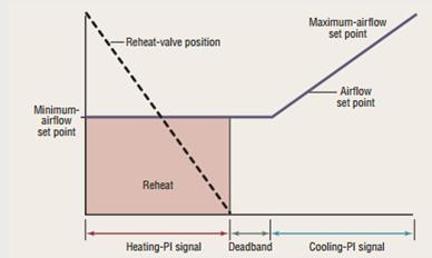
Single Maximum VAV Box Control
Courtesy: Taylor Engineering
Dual Maximum: raises the SAT as the first stage of heating, and increases the airflow to the zone as the second stage of heating.
1. The first stage of heating consists of modulating the zone supply air temperature setpoint up to a maximum setpoint no larger than 95ºF while the airflow is maintained at the dead band flow rate.
2. The second stage of heating consists of modulating the airflow rate from the dead band flow rate up to the heating maximum flow rate (50% of design flow rate).
Units
List:
Single Maximum
Dual Maximum
Input Restrictions
Fixed at Single Maximum if Control System Type is not DDC Control to the Zone Level
Standard Design
Dual Maximum
5.6.5.2 Fan Powered Boxes
Fan Powered Box Type
Applicability
thermal zones that have fan powered boxes
Definition
Defines the type of fan-powered induction box. This is either:
•Series; or
•Parallel
Units
List (see above)
Input Restrictions
As designed
Standard Design
Not applicable
Applicability
thermal zones that have fan powered boxes
Definition
The rated power input of the fan in a fan-powered box.
Units
W or W/cfm
Input Restrictions
As designed
Standard Design
Not applicable
Fan Powered Box Induced Air Zone
Applicability
thermal zones that have fan powered boxes
Definition
Zone from which a series or parallel fan-powered box draws its air
Units
List (of zones)
Input Restrictions
As designed
Standard Design
Not applicable
Parallel PIU Induction Ratio
Applicability
thermal zones that have fan powered boxes
Definition
The ratio of induction-side airflow of a fan-powered box at design heating conditions to the primary airflow
Units
Ratio
Input Restrictions
As designed
Standard Design
Not applicable
Parallel Fan Box Thermostat Setpoint
Applicability
thermal zones that have parallel fan powered boxes
Definition
The temperature difference above the heating setpoint at which the parallel fan is turned on
Units
Degrees Fahrenheit (°F)
Input Restrictions
2°F above the heating setpoint schedule
Standard Design
Not applicable
5.6.5.3 Zone
Exhaust
This group of building descriptors describes the rate of exhaust and the schedule or control for this exhaust. An exhaust system can serve one thermal zone or multiple thermal zones. Energy is summed for the exhaust system level, not the thermal zone level.
This section also contains unique inputs for kitchen exhaust systems that must meet requirements of section 140.9 of the Standards.
Kitchen Exhaust Hood Length
Applicability
Exhaust fans in spaces of type Kitchen
Definition
The exhaust hood length
Units
ft
Input Restrictions
As designed
Standard Design
Same as the proposed design
Kitchen Exhaust Hood Style
Applicability
Exhaust fans in spaces of type Kitchen
Definition
The hood style as defined in Table 140.9-A of the Standards
Units
List: Wall-mounted canopy, Single Island, Double Island, Eyebrow, Backshelf/Passover
Input Restrictions
As designed
Standard Design
Same as the proposed design
Kitchen Exhaust Hood Cooking Duty
Applicability
Exhaust fans in spaces of type Kitchen
Definition
The hood cooking duty as defined in Table140.9-A of the Standards
Units
List: Light Duty, Medium Duty, Heavy Duty, Extra Heavy Duty
Input Restrictions
As designed
Standard Design
Same as the proposed design
Exhaust Fan Name
Applicability
All thermal zones
Definition
A reference to an exhaust fan system that serves the thermal zone
Units
Text or other unique reference to an exhaust fan system defined in the secondary systems section.
Input Restrictions
As designed
Standard Design
Same as the proposed design
Laboratory Exhaust Rate Type
Applicability
All laboratory zones
Definition
The type of load that dictates lab exhaust rate requirements
Units
List, either:
Hood dominated
Load dominated
Input Restrictions
As designed
Standard Design
Same as the proposed design
Applicability
All thermal zones
Definition
Rate of exhaust from a thermal zone
Units
cfm
Input Restrictions
As designed for non-process zones
For laboratory zones, the exhaust air flow rate is prescribed:
15 ACH for hood dominated spaces, or
6 ACH for load dominated spaces
Standard Design
Same as the proposed design but not above the maximum standard design flow rates 'listed in Appendix 5.4A. Exception for kitchen space types with over 5,000 cfm of exhaust: the baseline is a function of the Kitchen Exhaust Hood Length, Kitchen Exhaust Hood Style and Kitchen Exhaust Hood Cooking Duty, and is determined by Table 140.9-A.
Exhaust Minimum Air Flow Rate
Applicability
All laboratory zones
Definition
Rate of exhaust from a zone
Units
cfm
Input Restrictions
As designed for non-process zones
For laboratory zones, the exhaust air flow rate is the maximum of the hood scheduled exhaust air flow rate and the minimum ventilation rate
Standard Design
For laboratory systems, the exhaust minimum air flow rate is the maximum of the hood scheduled exhaust flow rate and 6 ACH, the minimum ventilation rate
Exhaust Fan Schedule
Applicability
All thermal zones
Definition
Schedule indicating the pattern of use for exhaust air from the thermal zone. This input should consider the position of fume hood sash opening. For toilets and other exhaust applications, the schedule may coincide with the operation of the exhaust fan system.
Units
Data structure: schedule, fraction
Input Restrictions
As designed for non-covered process spaces
For laboratory spaces, if the hoods are constant volume the schedule shall be fixed at 0.90 for all hours of the year (24/7).
For laboratory spaces, if the hoods are variable volume the schedule shall be prescribed at the values in Appendix 5.4B.
Standard Design
Same as the proposed design for non-covered process spaces
Exhaust schedules for kitchen exhaust hoods for flow less than 5,000 cfm and for flow greater than 5,000 cfm are prescribed and specified in Appendix 5.4B.
Laboratory hood exhaust schedules for CAV and VAV hoods are prescribed and specified in Appendix 5.4B.
5.6.5.4 Outdoor Air
Ventilation
Applicability
All thermal zones
Definition
The source of ventilation for an HVAC system. The choices are:
•Natural (by operable openings)
•Forced (by fan)
Units
List: natural or forced
Input Restrictions
For residential units and hotel/motel guest rooms, as designed. (For software that cannot model outside air ventilation with residential systems that do not have a ducted air source, the ventilation source shall be none.) For all other occupancies, as designed.
Standard Design
For residential units, set to same as proposed, for all other occupancies, set equal to the same value for the proposed design.
Design Ventilation Rate
Applicability
All thermal zones
Definition
The quantity of ventilation air that is provided to the space for the specified thermal zone at maximum occupancy
Units
cfm or cfm/occupant
Input Restrictions
As designed, but not lower than code minimum (default value).
The default value shall be the larger of 15 cfm times the design occupancy from Appendix 5.4A or the conditioned floor area times the applicable ventilation rate from Appendix 5.4A or Table 120.1-A of the Standards.
Standard Design
The standard design outside air ventilation rate shall be the larger of 15 cfm times the design occupancy from Appendix 5.4A, or the conditioned floor area of the space times the applicable ventilation rate in Appendix 5.4A or Table 120.1-A of the Standards.
Minimum Ventilation Rate
Applicability
All thermal zones, excluding unconditioned spaces
Definition
The minimum quantity of ventilation air that must be provided to the space when it is occupied
Units
cfm or cfm/ft²
Input Restrictions
As designed, but not lower than code minimum (default value). The default value shall be the larger of 15 cfm times the design occupancy from Appendix 5.4A or the conditioned floor area times the applicable ventilation rate from Appendix 5.4A or Table 120.1-A of the Standards.
For labs the minimum ventilation rate shall not be less than 6 ACH at all times.
For spaces where demand control ventilation is installed, the minimum ventilation rate is specified by the greater of the rate in Table 120.1-A or 15 cfm times the scheduled occupancy for that hour;
For spaces where Occupant sensor ventilation controls are installed, the minimum ventilation rate shall be 25% of the area-based values in Table 120.1-A (e.g. 0.0375 cfm/ft2 for office) during hours when the occupancy schedule is 10% or less.
Standard Design
For spaces where demand control ventilation is required, the minimum ventilation rate is specified by the greater of the rate in Table 120.1-A or 15 cfm times the scheduled occupancy for that hour;
For systems serving laboratories, the airflow minimum for each lab space shall be 6 ACH.
For systems serving kitchens, the minimum outside air ventilation rate is the exhaust air ventilation rate minus available transfer air (available transfer shall be calculated from the building minimum outside airflow less any exhaust airflows other than kitchen exhausts) and minus 0.05 cfm/ft2 for exfiltration.
For all other spaces, the minimum ventilation rate is the same as the design ventilation rate in the standard design.
Ventilation Control Method
Applicability
All thermal zones
Definition
The method used to determine outside air ventilation needed for each hour in the simulation. This information is reported to the system serving the zone. The method of controlling outside air at the system level in response to this information is discussed under secondary systems. Options at the zone level are:
•Occupant sensors: When the space is occupied according to the prescribed occupancy schedule, the outside air requirement is equal to the design ventilation rate; otherwise, the outside air requirement is either 25% of the minimum ventilation rate or scheduled off (0).
•CO2 sensors in the space: The outside air is varied to maintain a maximum CO2 concentration in the space. This shall be approximated by multiplying the ventilation rate per occupant times the number of occupants for that hour. (When turnstile counts are used to automatically adjust ventilation levels based on occupancy, this method may also be used.)
•Fixed ventilation rate. Outside air is delivered to the zone at a constant rate and is equal to the design ventilation rate (see above).
Units
List (see above)
Input Restrictions
As designed. If the space includes a design occupant density greater than 25 persons per 1,000 ft2, and the system includes an airside economizer, the input is restricted to CO2 sensors in the space (a mandatory requirement).
Standard Design
For the federal tax credit Title 24 compliance, if the default occupancy from Appendix 5.4B is greater than 10025 persons per 1,000 ft² , set control method to CO2 sensors in the space, otherwise set to fixed ventilation rate.