Boiler Name
Applicability
All boilers
Definition
A unique descriptor for each boiler, heat pump, central heating heat-exchanger or heat recovery device.
Units
None
Input Restrictions
User entry. Where applicable, this should match the tags that are used on the plans for the proposed design.
Standard Design
Boilers are only designated in the baseline model if the Baseline System type uses hot water for space heating.
Boiler Fuel Source
Applicability
All boilers
Definition
The fuel source for the central heating equipment. The choices are:
•Gas
•Oil
•Electricity
Units
List (see above)
Input Restrictions
As designed
This input is restricted, based on the choice of Boiler Type, according to the following rules:
|
|
Electricity |
Gas |
Steam |
|
Steam Boiler |
|
|
Allowed |
|
Hot Water Boiler |
|
Allowed |
|
Standard Design
Gas
Boiler Type
Applicability
All boilers
Definition
The boiler type. Choices include:
•Steam Boiler
•Hot Water Boiler
•Heat-Pump Water Heater
Units
List (see above)
Input Restrictions
As designed
Standard Design
Hot water boiler
Boiler Draft Type
Applicability
All boilers
Definition
How combustion airflow is drawn through the boiler. Choices are:
•Natural (sometimes called atmospheric)
•Mechanical
Natural draft boilers use natural convection to draw air for combustion through the boiler. Natural draft boilers are subject to outside air conditions and the temperature of the flue gases.
Mechanical draft boilers enhance the air flow in one of three ways: 1) Induced draft, which uses ambient air, a steam jet, or a fan to induce a negative pressure which pulls flow through the exhaust stack; 2) Forced draft, which uses a fan and ductwork to create a positive pressure that forces air into the furnace, and 3) Balanced draft, which uses both induced draft and forced draft methods to bring air through the furnace, usually keeping the pressure slightly below atmospheric.
Units
List (see above)
Input Restrictions
As designed.
Standard Design
Mechanical (forced).
Number of Identical Boiler Units
Applicability
All boilers
Definition
The number of identical units for staging
Units
Numeric: integer
Input Restrictions
As designed. Default is 1.
Standard Design
The baseline building shall have one boiler for a when the baseline plant serves a conditioned floor area of 15,000 ft2 or less, and have two equally size boilers for plants serving more than 15,000 ft2.
Boiler Design Capacity
Applicability
All boilers
Definition
The heating capacity at design conditions
Units
Btu/h
Input Restrictions
As designed. If unmet load hours shall not exceed 150, see Section 2.6.1.for how the software handles undersized systems.
Standard Design
The boiler is sized to be 25% larger than the peak loads of the baseline building. Baseline boilers shall be sized using weather files containing 99.6% heating design temperatures and 0.5% dry-bulb and 1% wet-bulb cooling design temperatures.
Boiler Efficiency Type
Applicability
All boilers
Definition
The full load efficiency of a boiler is expressed as one of the following:
•Annual Fuel Utilization Efficiency (AFUE) is a measure of the boiler’s efficiency over a predefined heating season.
•Thermal Efficiency (Et) is the ratio of the heat transferred to the water divided by the heat input of the fuel.
•Combustion Efficiency (Ec) is the measure of how much energy is extracted from the fuel and is the ratio of heat transferred to the combustion air divided by the heat input of the fuel.
Units
List (see above)
Input Restrictions
None
Standard Design
Same as proposed design
Boiler Efficiency
Applicability
All boilers
Definition
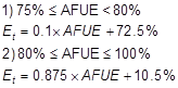
The full load efficiency of a boiler at rated conditions (see efficiency type above) expressed as a dimensionless ratio of output over input. The software must accommodate input in either Thermal Efficiency (Et), Combustion Efficiency (Ec) or Annual Fuel Utilization Efficiency (AFUE). The software shall make appropriate conversions to thermal efficiency if either AFUE or combustion efficiency is entered as the rated efficiency.
Where AFUE is provided, Et shall be calculated as follows:
(45)
All electric boilers will have an efficiency of 100%.
If combustion efficiency is entered, the compliance software shall convert the efficiency to thermal efficiency by the relation:
Et = Ec – 0.015
Units
Ratio
Input Restrictions
As designed
Standard Design
Boilers for the baseline design are assumed to have the minimum efficiency as 'listed in Table E-4 of the 2009 CEC Appliance Efficiency Standards.
Boiler Part-Load Performance Curve
Applicability
All boilers
Definition
An adjustment factor that represents the percentage full load fuel consumption as a function of the percentage full load capacity. This curve shall take the form of a quadratic equation as follows:
(46)
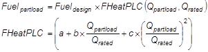
where
FHeatPLC The Fuel Heating Part Load Efficiency Curve
Fuelpartload The fuel consumption at part load conditions (Btu/h)
Fuel design The fuel consumption at design conditions (Btu/h)
Qpartload The boiler capacity at part load conditions (Btu/h)
Qrated The boiler capacity at design conditions (Btu/h)
a Constant
b Constant
c Constant
Units
Ratio
Input Restrictions
Prescribed to the part-load performance curve in ACM Appendix 5.7, based on the Boiler Draft Type.
Standard Design
The baseline building uses the mechanical draft fan curve in Appendix 5.7.
Boiler Forced Draft Fan Power
Applicability
All mechanical draft boilers
Definition
The fan power of the mechanical draft fan at design conditions.
Units
Nameplate Horsepower
Input Restrictions
As designed.
The software shall convert the user entry of motor HP to fan power in Watts by the following equation:
Fan Power = Motor HP x 746 x 0.5
Standard Design
Sized for an energy input ratio of 0.001018.(0.2984 W per kBtu/h heat input).
Boiler Minimum Unloading Ratio
Applicability
All boilers
Definition
The minimum unloading capacity of a boiler expressed as a percentage of the rated capacity. Below this level the boiler must cycle to meet the load.
Units
Percent (%)
Input Restrictions
As designed. If the user does not use the default value the software must indicate that supporting documentation is required on the output forms. Fixed at 1% (this accounts for jacket losses and start/stop losses).
Standard Design
1%
Boiler Minimum Flow Rate
Applicability
All boilers
Definition
The minimum flow rate recommended by the boiler manufacturer for stable and reliable operation of the boiler.
Units
gpm
Input Restrictions
As designed.
If the boiler(s) is piped in a primary only configuration in a variable flow system then the software shall assume there is a minimum flow bypass valve that allows the HW pump to bypass water from the boiler outlet back to the boiler inlet to maintain the minimum flow rate when boiler is enabled. Note that the boiler entering water temperature must accurately reflect the mixed temperature (colder water returning from the coil(s) and hotter bypass water) in order to accurately model boiler efficiency as a function of boiler entering water temperature.
Standard Design
0 gpm
Hot Water Supply Temperature
Applicability
All boilers
Definition
The temperature of the water produced by the boiler and supplied to the hot water loop
Units
Degrees Fahrenheit (°F)
Input Restrictions
As designed
Standard Design
Use 180°F for baseline boiler
Hot Water Return Temperature
Applicability
All boilers
Definition
The temperature of the water returning to the boiler from the hot water loop
Units
Degrees Fahrenheit (°F)
Input Restrictions
As designed
Standard Design
Use 140°F for baseline boiler design.
Hot Water Supply Temperature Reset
Applicability
All boilers
Definition
Variation of the hot water supply temperature with outdoor air temperature.
Units
Degrees Fahrenheit (°F)
Input Restrictions
As designed (Not allowed for non-condensing boilers)
Standard Design
The hot water supply temperature should vary according to the following:
180°F when outside air is < 20°F
ramp linearly between 180°F & 150°F when outdoor air is between 20°F and 50°F
150°F when outdoor air is > 50°F
Not applicable

Chiller Name
Applicability
All chillers
Definition
A unique descriptor for each chiller
Units
Text, unique
Input Restrictions
User entry. Where applicable, this should match the tags that are used on the plans.
Standard Design
Chillers are only designated when the baseline system uses chilled water
Chiller Type
Applicability
All chillers
Definition
The type of chiller, either a vapor-compression chiller or an absorption chiller.
Vapor compression chillers operate on the reverse-Rankine cycle, using mechanical energy to compress the refrigerant, and include:
•Reciprocating*
•Scroll*
•Screw*
•Centrifugal – uses rotating impeller blades to compress the air and impart velocity
•Direct Fired Single Effect Absorption – use a single generator & condenser
•Direct Fired Double Effect Absorption – use two generators/concentrators and condensers, one at a lower temperature and the other at a higher temperature. It is more efficient than the single effect, but it must use a higher temperature heat source.
•Indirect Fired Double Effect Absorption
•Gas Engine Driven
* Positive displacement – includes reciprocating (piston-style), scroll and screw compressors
Units
List (see above) The software shall support all chiller types 'listed above
Input Restrictions
As designed
Standard Design
The baseline building chiller is based on the design capacity of the standard design (baseline) as follows:
|
Building Peak Cooling Load |
Number and Type of Chiller(s) |
|
|
|
|
<= 300 tons |
1 water-cooled screw chiller |
|
>300 tons, < 600 tons |
2 water-cooled screw chillers, sized equally |
|
>= 600 tons |
A minimum of two (2) water-cooled centrifugal chillers, sized to keep the unit size below 800 tons |
Number of Identical Chiller Units
Applicability
All chillers
Definition
The number of identical units for staging.
Units
None
Input Restrictions
As designed. Default is 1.
Standard Design
From Table 47 above.
Chiller Fuel Source
Applicability
All chillers
Definition
The fuel source for the chiller. The choices are:
•Electricity (for all vapor-compression chillers)
•Gas (Absorption units only, designated as direct-fired units)
•Hot Water (Absorption units only, designated as indirect-fired units)
•Steam (Absorption units only, designated as indirect-fired units)
Units
List (see above)
Input Restrictions
As designed.
This input is restricted, based on the choice of Chiller Type, according to the following rules:
|
|
Electricity |
Gas |
Hot Water |
Steam |
|
Reciprocating |
allowed |
|
|
|
|
Scroll |
Allowed |
|
|
|
|
Screw |
Allowed |
|
|
|
|
Centrifugal |
Allowed |
|
|
|
|
Single Effect Absorption |
|
Allowed |
Allowed |
Allowed |
|
Direct Fired Double Effect Absorption |
|
Allowed |
Allowed |
Allowed |
|
Indirect Fired Absorption |
|
Allowed |
Allowed |
Allowed |
Standard Design
Electricity
Chiller Rated Capacity
Applicability
All chillers
Definition
The cooling capacity of a piece of heating equipment at rated conditions.
Units
Btu/h or tons
Input Restrictions
As designed. If unmet load hours are greater than 150 for any zone served by the chiller, the user must follow procedures outlined in Section 2.6.1|topic=2.6.1 Specifying HVAC Capacities for the Proposed Design to address undersized systems.
Standard Design
Determine loads for baseline building and oversize by 15%.
Chiller Rated Efficiency
Applicability
All chillers
Definition
The Efficiency of the chiller (Energy Efficiency Ratio (EER) for air-cooled chillers, kW/ton for water-cooled electric chillers and COP for fuel-fired and heat-driven chillers) at AHRI 550/590 rated full-load conditions.
Units
Ratio (kW/ton, COP, EER, depending on Chiller Type and Condenser Type)
Water-cooled electric chiller: kW/ton
Air-cooled or evaporatively cooled electric chiller: EER
All non-electric chillers: COP
Input Restrictions
As designed. Must meet the minimum requirements of Table 110.2-D.
Standard Design
Use the minimum efficiency requirements from Tables 110.2-D Path B.
If Chiller Type is Reciprocating, Scroll or Screw, use the efficiency for Positive Displacement chillers from Table 110.2-D.
Integrated Part-Load Value
Applicability
All chillers
Definition
The part-load efficiency of a chiller developed from a weighted average of four rating conditions, according to AHRI Standard 550.
Units
Ratio (kW/ton, COP, EER, depending on Chiller Type and Condenser Type)
Water-cooled electric chiller: kW/ton
Air-cooled or evaporatively cooled electric chiller: EER
All non-electric chillers: COP
Input Restrictions
As designed. Must meet the minimum requirements of Table 110.2-D.
Standard Design
Not used. When the standard design system has a chiller, the standard design will always use Path B performance curves.
Chiller Minimum Unloading Ratio
Applicability
All chillers
Definition
The minimum unloading capacity of a chiller expressed as a fraction of the rated capacity. Below this level the chiller must either cycle to meet the load or false-load the compressor (such as with hot gas bypass).
|
Chiller Type |
Default Unloading Ratio |
|
Reciprocating |
25% |
|
Screw |
15% |
|
Centrifugal |
10% |
|
Scroll |
25% |
|
Single Effect Absorption |
10% |
|
Double Effect Absorption |
10% |
Units
Percent (%)
Input Restrictions
As designed, but constrained to a minimum value of 10%.. If the user does not employ the default values, supporting documentation is required.
Standard Design
Use defaults 'listed above.
Chiller Minimum Part Load Ratio
Applicability
All chillers
Definition
The minimum unloading capacity of a chiller expressed as a fraction of the rated capacity. Below this level the chiller must cycle to meet the load. If the chiller minimum part-load ratio (PLR) is less than the chiller minimum unloading ratio, then the compliance software shall assume hot gas bypass operation between the minimum PLR and the minimum unloading ratio.
Units
Percent (%)
Input Restrictions
As designed, but constrained to a minimum value of 10%.. If the user does not employ the default values, supporting documentation is required.
Standard Design
When the standard design has a screw chiller, the minimum part load ratio is 15%. When the standard design has a centrifugal chiller, the minimum part load ratio is 10%.
Chiller Cooling Capacity Adjustment Curve
Applicability
All chillers
Definition
A curve or group of curves or other functions that represent the available total cooling capacity as a function of evaporator and condenser conditions and perhaps other operating conditions. The default curves are given as follows:
(47)

For air-cooled chillers:
(48)

For water-cooled chillers:
(49)

where
Qavailable Available cooling capacity at present evaporator and condenser conditions (MBH)
tchws The chilled water supply temperature (°F)
tcws The condenser water supply temperature (°F)
todb The outside air dry-bulb temperature (°F)
Qrated Rated capacity at AHRI conditions (MBH)
Note: If an air-cooled unit employs an evaporative condenser, todb is the effective dry-bulb temperature of the air leaving the evaporative cooling unit.
Separate curves are provided for Path A and Path B chillers in Appendix 5.7.
Units
Data structure
Input Restrictions
Prescribed curves are provided in Appendix 5.7 for the proposed design chiller type and the compliance path (Path A or Path B).. If the default curves are overridden, supporting documentation is required.
Standard Design
Use prescribed curve for Path B chiller as applicable to the standard design chiller type.
Electric Chiller Cooling Efficiency Adjustment Curves
Applicability
All chillers
Definition
A curve or group of curves that varies the cooling efficiency of an electric chiller as a function of evaporator conditions, condenser conditions and part-load ratio. Note that for variable-speed chillers, the part-load cooling efficiency curve is a function of both part-load ratio and leaving condenser water temperature. The default curves are given as follows:
(50) 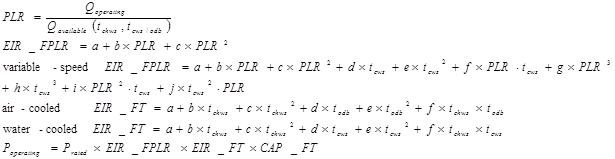
where
PLR Part load ratio based on available capacity (not rated capacity)
Qoperating Present load on chiller (Btu/h)
Qavailable Chiller available capacity at present evaporator and condenser conditions (Btu/h)
tchws The chilled water supply temperature (°F)
tcws The condenser water supply temperature (°F)
todb The outside air dry-bulb temperature (°F)
Prated Rated power draw at AHRI conditions (kW)
Poperating Power draw at specified operating conditions (kW)
Note: If an air-cooled chiller employs an evaporative condenser, todb is the effective dry-bulb temperature of the air leaving the evaporative cooling unit.
Units
Data structure
Input Restrictions
Curves are prescribed in Appendix 5.7 given the chiller capacity and type. A separate set of curves is be provided for Path A chillers and Path B chillers. The Path is determined by comparing software inputs of full-load efficiency and integrated part-load value with the requirements of Standards Table 110.2-D.
Standard Design
Use Path B curves specified in Appendix 5.7.
Fuel and Steam Chiller Cooling Efficiency Adjustment Curves
Applicability
All chillers
Definition
A curve or group of curves that varies the cooling efficiency of a fuel-fired or steam chiller as a function of evaporator conditions, condenser conditions, and part-load ratio. The default curves are given as follows:
Default Curves for Steam-Driven Single and Double Effect Absorption Chillers
(51)
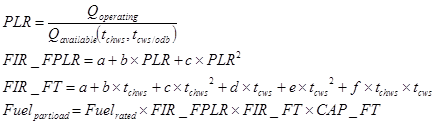
Default Curves for Direct-Fired Double Effect Absorption Chillers
(52)
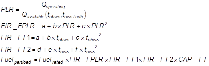
The default curves for engine driven chillers are the same format as those for the Steam-Driven Single and Double Effect Absorption Chillers but there are three sets of curves for different ranges of operation based on the engine speed.
where
PLR Part load ratio based on available capacity (not rated capacity)
FIR-FPLR A multiplier on the fuel input ratio (FIR) to account for part load conditions
FIR-FT A multiplier on the fuel input ratio (FIR) to account for the chiller water supply temperature and the condenser water temperature
FIR-FT1 A multiplier on the fuel input ratio (FIR) to account for chilled water supply temperature
FIR-FT2 A multiplier on the fuel input ratio (FIR) to account for condenser water supply temperature
CAP-FT A multiplier on the capacity of the chiller (see Equation (48))
Qoperating Present load on chiller (in Btu/h)
Qavailable Chiller available capacity at present evaporator and condenser conditions (in Btu/h)
tchws The chilled water supply temperature (in °F)
tcws The condenser water supply temperature (in °F)
todb The outside air dry-bulb temperature (°F)
Fuelrated Rated fuel consumption at AHRI conditions (in Btu/h)
Fuelpartload Fuel consumption at specified operating conditions (in Btu/h)
Units
Data structure
Input Restrictions
Restricted to curves specified in Appendix 5.7.
Standard Design
Use prescribed curves specified in Appendix 5.7
Chilled Water Supply Temperature
Applicability
All chillers
Definition
The chilled water supply temperature of the chiller at design conditions
Units
Degrees Fahrenheit (°F)
Input Restrictions
As designed
Standard Design
The baseline chilled water supply temperature is set to 44°F.
Chilled Water Return Temperature
Applicability
All chillers
Definition
The chilled water return temperature setpoint at design conditions
Units
Degrees Fahrenheit (°F)
Input Restrictions
As designed
Standard Design
The standard design chilled water return temperature is set to 64°F.
Chilled Water Supply Temperature Control Type
Applicability
All chillers
Definition
The method by which the chilled water setpoint temperature is reset. The chilled water setpoint may be reset based on demand or outdoor air temperature.
Units
List
None
Outside air-based reset
Demand-based reset
Input Restrictions
As designed.
Standard Design
Outside-air based reset
Chilled Water Supply Temperature Reset
Applicability
All chillers
Definition
The reset schedule for the chilled water supply temperature. The chilled water setpoint may be reset based on demand or outdoor air temperature.
Units
Degrees Fahrenheit (°F)
Input Restrictions
As designed.
Standard Design
10°F from design chilled water supply temperature
The chilled water supply temperature reset follows an outside-air reset scheme, where the setpoint is 44F at outside air conditions of 80F dry-bulb and above, the setpoint is 54F at outside air conditions of 60F dry-bulb and below, and ramps linearly from 44F to 54F as the outside air dry-bulb temperature varies between 80F and 60F.
Condenser Type
Applicability
All chillers
Definition
The type of condenser for a chiller. The choices are:
•Air-Cooled
•Water-Cooled
•Evaporatively-Cooled
Air-cooled chillers use air to cool the condenser coils. Water-cooled chillers use cold water to cool the condenser and additionally need either a cooling tower or a local source of cold water. Evaporatively-cooled chillers are similar to air-cooled chillers, except they use a water mist to cool the condenser coil which makes them more efficient.
Units
List (see above)
Input Restrictions
As designed
Standard Design
The baseline chiller is always assumed to have a water-cooled condenser, although the chiller type will change depending on the design capacity.
Standard Design Summary. Standard Design system 6 has one or more cooling towers. One tower is assumed to be matched to each standard design chiller. Each standard design chiller has its own condenser water pump that operates when the chiller is brought into service. The range between the condenser water return (CWR) and condenser water supply (CWS) is 10 F. The baseline building condenser pumping energy is assumed to be 12 W/gpm. The cooling tower is assumed to have a variable-speed fan that is controlled to provide a CWS equal to the design wet-bulb temperature when weather permits. The design approach shall be 10°F.
Cooling Tower Name
Applicability
All cooling towers
Definition
A unique descriptor for each cooling tower
Units
Text, unique
Input Restrictions
User entry. Where applicable, this should match the tags that are used on the plans.
Standard Design
Descriptive name that keys the baseline building plant
Cooling Tower Type
Applicability
All cooling towers
Definition
The type of cooling tower employed. The choices are:
•Open tower, centrifugal fan
•Open tower, axial fan
Open cooling towers collect the cooled water from the tower and pump it directly back to the cooling system. Closed towers circulate the evaporated water over a heat exchanger to indirectly cool the system fluid.
Units
List (see above)
Input Restrictions
As designed
Standard Design
The baseline cooling tower is an open tower axial fan device
Cooling Tower Capacity
Applicability
All cooling towers
Definition
The tower thermal capacity per cell adjusted to CTI (Cooling Technology Institute) rated conditions of 95 °F condenser water return, 85 °F condenser water supply, and 78 °F wet-bulb with a 3 gpm/nominal ton water flow. The default cooling tower curves below are at unity at these conditions.
Units
Btu/h
Input Restrictions
As designed
Standard Design
The baseline building chiller is autosized and increased by 15%. The tower is sized to supply 85 °F condenser water at design conditions for the oversized chiller.
Cooling Tower Number of Cells
Applicability
All cooling towers
Definition
The number of cells in the cooling tower. Each cell will be modeled as equal size. Cells are subdivisions in cooling towers into individual cells, each with their own fan and water flow, and allow the cooling system to respond more efficiently to lower load conditions.
Units
Numeric: integer
Input Restrictions
As designed
Standard Design
One cell per tower and one tower per chiller.
Cooling Tower Total Fan Horse Power
Applicability
All cooling towers
Definition
The sum of the nameplate rated horsepower (hp) of all fan motors on the cooling tower. Pony motors should not be included.
Units
Gpm/hp or unitless if energy input ratio (EIR) is specified (If the nominal tons but not the condenser water flow is specified, the condenser design water flow shall be 3.0 gpm per nominal cooling ton.)
Input Restrictions
As designed, but the cooling towers shall meet minimum performance requirements in Table 110.2-G.
Standard Design
The cooling tower fan horsepower is 60 gpm/hp.
Cooling Tower Design Wet-Bulb
Applicability
All cooling towers
Definition
The design wet-bulb temperature that was used for selection and sizing of the cooling tower.
Units
Degrees Fahrenheit (°F)
Input Restrictions
Specified from design wet-bulb conditions from Reference Appendix JA2 for the city where the building is located, or the city closest to where the building is located.
Standard Design
Specified from design wet-bulb conditions from Reference Appendix JA2 for the city where the building is located, or from the city closest to where the building is located.
Cooling Tower Design Entering Water Temperature
Applicability
All cooling towers
Definition
The design condenser water supply temperature (leaving tower) that was used for selection and sizing of the cooling tower.
Units
Degrees Fahrenheit (°F)
Input Restrictions
As designed. Default to 85°F.
Standard Design
85°F or 10°F above the design wet-bulb temperature, whichever is lower
Cooling Tower Design Return Water Temperature
Applicability
All cooling towers
Definition
The design condenser water return temperature (entering tower) that was used for selection and sizing of the cooling tower.
Units
Degrees Fahrenheit (°F)
Input Restrictions
As designed. Default to 95°F.
Standard Design
Set to a range of 10 F (10°F above the cooling tower design entering water temperature.
Cooling Tower Capacity Adjustment Curve(s)
Applicability
All cooling towers
Definition
A curve or group of curves that represent the available total cooling capacity as a function of outdoor air wet-bulb, condenser water supply and condenser water return temperatures. The default curves are given as follows:
Option 1 (DOE-2 based performance curves)
(53)
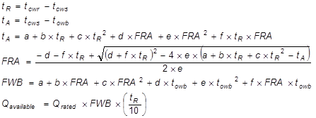
Where
Qavailable Available cooling capacity at present outside air and condenser water conditions (MBH)
Qrated Rated cooling capacity at CTI test conditions (MBH)
tcws The condenser water supply temperature (in °F)
tcwr The condenser water return temperature (in °F)
towb The outside air wet-bulb temperature (°F)
tR The tower range (in °F)
tA The tower approach (in °F)
FRA An intermediate capacity curve based on range and approach
FWB The ratio of available capacity to rated capacity (gpm/gpm).
Option 2: CoolTools performance curve (EnergyPlus)
Approach = Coeff(1) + Coeff(2)•FRair + Coeff(3)•(FRair)2 +Coeff(4)•(FRair)3 + Coeff(5)•FRwater + Coeff(6)•FRair•FRwater + Coeff(7)•(FRair)2•FRwater + Coeff(8)•(FRwater)2 + Coeff(9)•FRair•(FRwater)2 +
Coeff(10)•(FRwater)3 + Coeff(11)•Twb + Coeff(12)•FRair•Twb + Coeff(13)•(FRair)2•Twb + Coeff(14)•FRwater•Twb + Coeff(15)•FRair•FRwater•Twb + Coeff(16)•(FRwater)2•Twb +
Coeff(17)•(Twb)2 + Coeff(18)•FRair•(Twb)2 + Coeff(19)•FRwater•(Twb)2 + Coeff(20)•(Twb)3 + Coeff(21)•Tr + Coeff(22)•FRair•Tr + Coeff(23)•FRair•FRair•Tr + Coeff(24)•FRwater•Tr + Coeff(25)•FRair•FRwater•Tr +
Coeff(26)•(FRwater)2•Tr + Coeff(27)•Twb•Tr + Coeff(28)•FRair•Twb•Tr + Coeff(29)•FRwater•Twb•Tr +
Coeff(30)•(Twb)2•Tr + Coeff(31)•(Tr)2 + Coeff(32)•FRair•(Tr)2 + Coeff(33)•FRwater•(Tr)2 + Coeff(34)•Twb•(Tr)2 + Coeff(35)•(Tr)3
Where
FRair – ratio of airflow to airflow at design conditions
FRwater – ratio of water flow to water flow at design conditions
Tr – tower range (deg F)
Twb – wet-bulb temperature
Coefficients for this performance curve are provided in Appendix 5.7.
Data structure
Input Restrictions
User may only use one of the two curves specified in Appendix 5.7.
Standard Design
Use one of the prescribed curves defined in Appendix 5.7.
Cooling Tower Set Point Control
Applicability
All cooling towers
Definition
The type of control for the condenser water supply. The choices are:
•Fixed
•Wet-bulb reset
A fixed control will modulate the tower fans to provide the design condenser water supply temperature at all times when possible. A wet-bulb reset control will reset the condenser water setpoint to a fixed approach to outside air wet-bulb temperature. The approach defaults to 10°F. A lower approach may be used with appropriate documentation.
Units
List (see above)
Input Restrictions
As designed.
Standard Design
Fixed at the 0.4% design wet-bulb temperature, which is prescribed and specified for each of the 86 weather data files
Cooling Tower Capacity Control
Applicability
All cooling towers
Definition
Describes the modulation control employed in the cooling tower. Choices include:
•Fluid Bypass provides a parallel path to divert some of the condenser water around the cooling tower at part-load conditions
•Fan Cycling is a simple method of capacity control where the tower fan is cycled on and off. This is and is often used on multiple-cell installations.
•Two-Speed Fan/Pony Motor. From an energy perspective, these are the same. A lower horsepower pony motor is an alternative to a two-speed motor; the pony motor runs at part-load conditions (instead of the full sized motor) and saves fan energy when the tower load is reduced. Additional building descriptors are triggered when this method of capacity control is selected.
•Variable Speed Fan. A variable frequency drive is installed for the tower fan so that the speed can be modulated.
Units
List (see above)
Input Restrictions
As designed.
Standard Design
Variable-speed fan
Cooling Tower Low-Speed Airflow Ratio
Applicability
All cooling towers with two-speed or pony motors
Definition
The percentage full load airflow that the tower has at low speed or with the pony motor operating. This is equivalent to the percentage full load capacity when operating at low speed.
Units
Ratio
Input Restrictions
As designed.
Standard Design
Not applicable
Cooling Tower Low-Speed kW Ratio
Applicability
All cooling towers with two-speed or pony motors
Definition
The percentage full load power that the tower fans draw at low speed or with the pony motor operating
Units
Ratio
Input Restrictions
Calculated, using the as-designed flow ratio and the cooling tower power adjustment curve below
Standard Design
Not applicable
Cooling Tower Power Adjustment Curve
Applicability
All cooling towers with VSD control
Definition
A curve that varies the cooling tower fan energy usage as a function of part-load ratio for cooling towers with variable speed fan control. The default curve is given as follows:
(54)
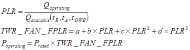
where
PLR Part load ratio based on available capacity (not rated capacity)
Qoperating Present load on tower (in Btu/h)
Qavailable Tower available capacity at present range, approach, and outside wet-bulb conditions (in Btu/h).
towb The outside air wet-bulb temperature (°F)
tR The tower range (°F)
tA The tower approach (°F)
Prated Rated power draw at CTI conditions (kW)
Poperating Power draw at specified operating conditions (kW)
|
Coefficient |
TWR-FAN-FPLR |
|
A |
0.33162901 |
|
B |
-0.88567609 |
|
C |
0.60556507 |
|
D |
0.9484823 |
Units
Data structure
Input Restrictions
User shall use only default curves.
Standard Design
Use default curves given above.
Cooling Tower Minimum Speed
Applicability
All cooling towers with a VSD control
Definition
The minimum fan speed setting of a VSD controlling a cooling tower fan expressed as a ratio of full load speed.
Units
Ratio
Input Restrictions
As designed. The default is 0.50.
Standard Design
0.5
Baseline Building Summary. None of the baseline building systems use a water-side economizer.
Water-Side Economizer Name
Applicability
All water-side economizers
Definition
The name of a water-side economizer for a cooling system
Units
Text, unique
Input Restrictions
Descriptive reference to the construction documents. The default is no water-side economizer.
Standard Design
Water Economizer Type
Applicability
All water-side economizers
Definition
The type of water-side economizer. Choices include:
•None
•Heat exchanger in parallel with chillers. This would be used with an open cooling tower is often referred to as a non-integrated economizer, because the chillers are locked out when the plant is in economizer mode.
•Heat exchanger in series with chillers. This would be used with an open cooling tower and is often referred to as an integrated, because the chillers can operate simultaneously with water economizer operation.
•Direct water economizer. This would be used with a closed cooling tower. In this case, a heat exchanger is not needed. This type works only as a non-integrated economizer. (also known as strainer-cycle)
•Thermo-cycle (also known as refrigerant migration). With thermo-cycle, bypass valves allow for the flow to vapor refrigerant to the condenser and allow gravity flow of liquid refrigerant to the evaporator without use of the compressor. Only some chillers have this capability and capacity may be limited under this mode. There is no additional piping; the cooler water from the tower is brought directly to the chiller(s) and the chiller(s) respond by shutting down the compressor and relying on thermal forces to drive the refrigerant. This method is also known as “thermosiphon” since thermal gradients passively move refrigerant between the evaporator and condenser.
Units
List (see above)
Input Restrictions
As designed
Standard Design
No water economizer
Water-Side Economizer HX Effectiveness
Applicability
Water-side economizers with an open cooling tower
Definition
The effectiveness of a water-side heat exchanger at design conditions. This is defined as:
(55)

Where
Qecon The maximum load that the economizer can handle
mCHW The chilled water flow rate
Cp The chilled water specific heat
TCHW,R The chilled water return temperature
TCW,S Condenser water supply temperature
WSEeff The effectiveness of the water-side economizer coil
tea The entering coil air dry-bulb temperature (°F)
tla The leaving coil air dry-bulb temperature (°F)
tea The entering coil water temperature (°F)
Units
Ratio
Input Restrictions
As designed. The default is 60%.
Standard Design
No water economizer
Water-Side Economizer Operating Range
Applicability
All water-side economizers
Definition
The minimum temperature difference between the chilled water inlet to the heat exchanger and the condenser water inlet to the heat exchanger that is required to enable the water-side economizer.
Units
Degrees Fahrenheit (°F)
Input Restrictions
As designed. Defaults to 4°F.
Standard Design
No water economizer
Water-Side Economizer Maximum CWS
Applicability
All water-side economizers
Definition
The control temperature (condenser water supply temperature) above which the water-side economizer is disabled.
Units
Degrees Fahrenheit (°F)
Input Restrictions
As designed. Defaults to 50°F.
Standard Design
No water economizer
Water-Side Economizer Availability Schedule
Applicability
All water-side economizers
Definition
A schedule which represents the availability of the water-side economizer
Units
Data structure: schedule, on/off
Input Restrictions
As designed
Standard Design
No water economizer
Water-Side Economizer Auxiliary kW
Applicability
Water-side economizers with an open tower
Definition
The electrical input (pumps and auxiliaries) for a dedicated pump for the chilled water side of the heat exchanger. This power is in excess of the condenser water pumps and cooling tower fans for the system during water-side economizer operation.
Units
KW or kW/ton
Input Restrictions
As designed
Standard Design
No water economizer
Baseline Building Summary. Hot water pumping in the baseline building shall be modeled as a variable flow primary only system. Two-way valves are assumed at the heating coils.
Chilled water pumping in the baseline building (system 6) is a primary system. Each chiller has its own primary and condenser water pumps that operate when the chiller is activated. For plants less than or equal to 300 tons, the secondary pump “rides the curve” for larger plants, the pump has a variable speed drive. The chilled water pump shall be variable speed and the condenser water pump shall be fixed speed.
General Notes. The building descriptors in this section are repeated for each pumping system. See the Pump Service building descriptor for a list of common pump services.
Pump Name
Applicability
All pumps
Definition
A unique descriptor for each pump
Units
Text, unique
Input Restrictions
User entry. Where applicable, this should match the tags that are used on the plans.
Standard Design
Same as the proposed design. If there is no equivalent in the proposed design, assign a sequential tag to each piece of equipment. The sequential tags should indicate the pump service as part of the descriptor (e.g. CW for condenser water, CHW for chilled water, or HHW for heating hot water).
Pump Service
Applicability
All pumps
Definition
The service for each pump. Choices include:
•Chilled water
•Chilled water (primary)
•Chilled water (secondary)
•Heating water
•Heating water (primary)
•Heating water (secondary)
•Service hot water
•Condenser water
•Loop water (for hydronic heat pumps)
Units
List (see above)
Input Restrictions
As designed
Standard Design
As needed by the baseline building system
Number of Pumps
Applicability
All pumps
Definition
The number of identical pumps in service in a particular loop, e.g. the heating hot water loop, chilled water loop, or condenser water loop
Units
Numeric: integer
Input Restrictions
As designed
Standard Design
There will be one heating hot water pump for each boiler, one chilled water pump, and one condenser water pump for each chiller.
Water Loop Design
Applicability
All pumps
Definition
The heating and cooling delivery systems can consist of a simple primary loop system, or more complicated primary/secondary loops or primary/secondary/tertiary loops.
Units
List (see above)
Input Restrictions
As designed
Standard Design
Assume primary loops only for heating hot water. For chilled water loops, a primary loop design is assumed s.
Applicability
All pumps
Definition
Software commonly models fans in one of two ways: The simple method is for the user to enter the electric power per unit of flow (W/gpm). This method is commonly used for smaller systems. A more detailed method requires a specification of the pump head, design flow, impeller and motor efficiency.
Units
List: Power-Per-Unit-Flow or Detailed
Input Restrictions
Detailed
Standard Design
Detailed for Chilled Water and Condenser Water Pumps; Power-per-unit-flow for Heating hot water and Service hot water pumps
Pump Motor Power-Per-Unit-Flow
Applicability
All proposed design pumps that use the Power-Per-Unit-Flow method.
Definition
The electric power of the pump divided by the flow at design conditions.
Units
W/gpm
Input Restrictions
As designed
Standard Design
Not applicable for chilled water and condenser water pumps; 19 W/gpm for heating hot water and service hot water pumps
Pump Motor Horsepower
Applicability
All pumps
Definition
The nameplate motor horsepower
Units
horsepower
Input Restrictions
Constrained to be a value from the following list of standard motor sizes:
A Standard Motor Size table (hp) is defined as: 1/12, 1/8, ¼, ½, ¾, 1, 1.5, 2, 3, 5, 7.5, 10, 15, 20, 25, 30, 40, 50, 60, 75, 100, 125, 150, 200
Standard Design
Not applicable
Pump Design Head
Applicability
All baseline building pumps and proposed design pumps that use the Detailed method.
Definition
The head of the pump at design flow conditions.
Units
ft of w.g.
Input Restrictions
As designed, but subject to an input restriction. The user inputs of Pump Design Head, Impeller Efficiency and Cooling Tower Design Entering Water Temperature and Cooling Tower Design Return Water Temperature shall be used to calculate the proposed brake horsepower. This shall be compared to the Pump Motor Horsepower for the next smaller motor size (MHPi-1) than the one specified by the user (MHPi).
The Proposed Design Pump Design Head shall be constrained so that the resulting brake horsepower is no smaller than 95% of the next smaller motor size:
Proposed Design bhp = min(Proposed Design bhpuser_head, 0.95 x MHPi-1)
Where
Proposed Design bhp – is the brake horsepower used in the simulation
Proposed Design bhpuser_head = the brake horsepower resulting from the user input of design head
MHPi = the Pump Motor Horsepower specified by the user
i = the index into the Standard Motor Size table for the user motor horsepower
MHPi-1 = the motor horsepower for the next smaller motor size. For example, if the user-specified Pump Motor Horsepower is 25, the next smaller motor size in the table above is 20.
Since all other user inputs that affect the proposed design brake horsepower are not modified, the Proposed Design Pump Design Head is adjusted in the same proportion as the pump brake horsepower in the equation above. If the user-entered Pump Design Head results in a brake horsepower that is at least 95% of the horsepower of the next smaller motor size, no modification of the user input is required.
Standard Design
For chilled water pumps, 40 ft plus an additional allowance of 0.03 ft/ton, but not to exceed 100 ft
For condenser water pumps, 45 ft
Impeller Efficiency
Applicability
All pumps in proposed design that use the detailed modeling method
Definition
The full load efficiency of the impeller
Units
Ratio
Input Restrictions
As designed
Standard Design
70%
Motor Efficiency
Applicability
All pumps in proposed design that use the detailed modeling method
Definition
The full load efficiency of the pump motor
Units
Ratio
Input Restrictions
As designed
Standard Design
Not applicable T The motor efficiency is taken from Table 29, using the next larger motor size than the calculated Standard Design brake horsepower.
Pump Minimum Speed
Applicability
All two-speed or variable-speed pumps
Definition
The minimum pump speed for a two-speed for variable-speed pump. For two-speed pumps this is typically 0.67 or 0.5. Note that the pump minimum speed is not necessarily the same as the minimum flow ratio, since the system head may change.
Units
Ratio
Input Restrictions
As designed
Standard Design
0.10.
Pump Minimum Flow Ratio
Applicability
Primary Chilled water pumps
Definition
The minimum fraction of design flow when the pump is operating at its minimum speed. Note that the pump minimum speed is not necessarily the same as the minimum flow ratio, since the system head may change.
Units
Ratio
Input Restrictions
As designed
Standard Design
0.3
Pump Design Flow (GPM)
Applicability
All pumps
Definition
The flow rate of the pump at design conditions. This is derived from the load, and the design supply and return temperatures.
Units
gpm or gpm/ton for condenser and primary chilled water pumps
Input Restrictions
Not a user input
Standard Design
The temperature change on the evaporator side of the chillers is 20 F (64 F less 44 F) and this equates to a flow of 1.2 gpm/ton. The temperature change on the condenser side of the chillers is 12 F, which equates to a flow of 2.0 gpm/ cooling ton. A VSD is required for heating pumps when the service area is greater than or equal to 120,000 ft². For hot water pumps servicing boilers, the flow rate in gpm shall correspond to a loop temperature drop of 40°F.
Pump Control Type
Applicability
All pumps
Definition
The type of control for the pump. Choices are:
•Fixed speed, fixed flow
•Fixed speed, variable flow (the default, with flow control via a valve)
•Two-speed
•Variable speed, variable flow
Units
None
Input Restrictions
As designed. The default is “Fixed Speed, Variable Flow” which models the action of a constant speed pump riding the curve against 2-way control valves.
Standard Design
The chilled water pumping for systems 7 and 8 is primary/secondary with variable flow. When the chilled water system has a capacity of less than 300 tons, the secondary system pumps shall ride the pump curve. When the chilled water system has a capacity of more than 300 tons, the secondary chilled water pumps shall be variable speed. Chilled water pumps used in the primary loop shall be fixed speed, fixed flow. Condenser water pumps shall be modeled as fixed speed, fixed flow.
The chilled water pumps shall be modeled as variable-speed, variable flow, and the condenser water pumps shall be modeled as fixed speed. The hot water pumps shall be modeled as fixed-speed, variable flow, riding the curve.
Pump Operation
Applicability
All pumps
Definition
The type of pump operation can be either On-Demand, Standby or Scheduled. On-Demand operation means the pumps are only pumping when their associated equipment is cycling, so chiller and condenser pumps are on when the chiller is on and the heating hot water pump operates when its associated boiler is cycling. Standby operation allows hot or chilled water to circulate through the primary loop of a primary/secondary loop system or through a reduced portion of a primary-only system, assuming the system has appropriate 3-way valves. Scheduled operation means that the pumps and their associated equipment are turned completely off according to occupancy schedules, time of year, or outside conditions. Under scheduled operation, when the systems are on they are assumed to be in On-Demand mode.
Units
List (see above)
Input Restrictions
As designed
Standard Design
The baseline system pumps are assumed to operate in On-Demand mode. The chilled water and condenser pumps are tied to the chiller operation, cycling on and off with the chiller, and the heating hot water pumps are tied to the boiler operation.
Pump Part Load Curve
Applicability
All pumps
Definition
A part-load power curve for the pump
(56)

(57)

where
PLR Part load ratio (the ratio of operating flow rate in gpm to design flow rate in gpm)
Ppump Pump power draw at part-load conditions (W)
Pdesign Pump power draw at design conditions (W)
|
Default (No Reset) |
DP Reset | |
|
a |
0 |
0 |
|
b |
0.5726 |
0.0205 |
|
c |
-0.301 |
0.4101 |
|
d |
0.7347 |
0.5753 |
Source:
Units
Data structure
Input Restrictions
Default is Default (No Reset). The DP Reset curve may only be selected if the DDC Control Type building descriptor indicates that the building has DDC controls.
Standard Design
DP Reset curve for chilled water pumps. Heating Hot water pump power is assumed to be constant even though the pump is riding the curve.
There are multiple ways to model thermal storage in the proposed design. The baseline building does not have thermal storage. Stratified storage tanks with a chilled water storage medium are not supported by the ACM.
Storage Type
Applicability
All thermal storage systems
Definition
A type of thermal energy storage (TES) that indicates the storage medium.
Units
List
Input Restrictions
Ice, Chilled Water
Standard Design
No thermal storage systems
Configuration
Applicability
All thermal storage systems
Definition
Indication of how the TES is configured and operated in relation to the chilled water cooling
Units
List
Input Restrictions
Series, Chiller Upstream
Series, Chiller Downstream
Parallel
Standard Design
No thermal storage systems
Ice Storage Type
Applicability
All thermal storage systems with Storage Type=Ice
Definition
Indication of the storage type for ice storage
Units
List
Input Restrictions
IceOnCoilExternal
IceOnCoilInternal
Standard Design
No thermal storage systems
Storage Capacity
Applicability
All thermal storage systems using ice storage
Definition
Nominal Storage Capacity of the tank
Units
GJ
Input Restrictions
None
Standard Design
No thermal storage systems
Tank Volume
Applicability
All thermal storage systems using ice storage
Definition
Nominal Storage Capacity of the tank
Units
m3
Input Restrictions
None
Standard Design
No thermal storage systems
CHW Setpoint Schedule
Applicability
All thermal storage systems using ice storage
Definition
Nominal Storage Capacity of the tank
Units
Series, deg F
Input Restrictions
None
Standard Design
No thermal storage systems
Deadband Temperature Difference
Applicability
All thermal storage systems using chilled water
Definition
The deadband temperature difference between enabling and disabling use of the TES system for cooling
Units
Degrees F
Input Restrictions
None
Standard Design
No thermal storage systems
Minimum Temperature Limit
Applicability
All thermal storage systems using chilled water
Definition
The minimum allowed temperature of the tank, below which charging of the tank cannot occur
Units
Deg F
Input Restrictions
None
Standard Design
No thermal storage systems
Storage Tank Location Indicator
Applicability
All thermal storage systems using ice storage
Definition
Nominal Storage Capacity of the tank
Units
List
Input Restrictions
Schedule, Zone, or Exterior.
If Schedule, the ambient temperature schedule must be specified. If Zone, the Zone name must be specified.
Standard Design
No thermal storage systems
Storage Tank Heat Gain Coefficient
Applicability
All thermal storage systems using chilled water
Definition
The heat transfer coefficient between the tank and the ambient surroundings
Units
W/K
Input Restrictions
None
Standard Design
No thermal storage systems
Use Side Heat Transfer Effectiveness
Applicability
All thermal storage systems using chilled water
Definition
The heat transfer effectiveness between the use side water and the tank water
Units
none
Input Restrictions
Between 0 and 1
Standard Design
No thermal storage systems
Use Side Design Flow Rate
Applicability
All thermal storage systems using chilled water
Definition
Design flow rate through the use side of the storage tank
Units
gpm
Input Restrictions
None
Standard Design
No thermal storage systems
Source Side Heat Transfer Effectiveness
Applicability
All thermal storage systems using chilled water
Definition
The heat transfer effectiveness between the source side water and the tank water
Units
none
Input Restrictions
Between 0 and 1
Standard Design
No thermal storage systems
Source Side Design Flow Rate
Applicability
All thermal storage systems using chilled water
Definition
Design flow rate through the source side of the storage tank
Units
gpm
Input Restrictions
None
Standard Design
No thermal storage systems
Tank Recovery Time
Applicability
All thermal storage systems using ice storage
Definition
This is the time in hours for the tank to cool from 14.4°C to 9°C. This input is only used if the source side design flow rate is not specified.
Units
hours
Input Restrictions
None
Standard Design
No thermal storage systems
Heat Recovery Name
Applicability
All heat recovery systems
Definition
A name assigned to a heat recovery system. This would provide a link to the construction documents.
Units
Text, unique
Input Restrictions
As designed
Standard Design
No heat recovery systems
Heat Recovery Device Type
Applicability
All heat recovery systems
Definition
The type of heat recovery equipment. Choices include:
•Double-Bundled Chiller
•Generator
•Engine-Driven Chiller
•Air Conditioning Unit
•Refrigerated Casework
Units
List (see above)
Input Restrictions
As designed
Standard Design
Heat recovery systems are not included in the baseline system.
Heat Recovery Loads
Applicability
All heat recovery systems
Definition
The loads met by the heat recovery system. Choices include:
•Space heating
•Process heating
More than one load may be selected.
Units
List (see above)
Input Restrictions
As designed
Standard Design
Not required in the baseline system.
Plant management is a method of sequencing equipment. Separate plant management schemes may be entered for chilled water systems, hot water systems, etc. The following building descriptors are specified for each load range, e.g. when the cooling load is below 300 tons, between 300 tons and 800 tons, and greater than 800 tons.
Equipment Type Managed
Applicability
All plant systems
Definition
The type of equipment under a plant management control scheme. Choices include:
•Chilled water cooling
•Hot water space heating
•Condenser water heat rejection
•Electrical generation
Units
None
Input Restrictions
As designed
Standard Design
Same as the proposed design
Equipment Schedule
Applicability
All plant equipment
Definition
A schedule which identifies when the equipment is in service.
Units
Data structure
Input Restrictions
As designed
Standard Design
Where multiple equipment is used, they shall be staged in operation.
Equipment Operation
Applicability
All plant equipment
Definition
Equipment operation can be either On-Demand or Always-On. On-Demand operation means the equipment cycles on when it is scheduled to be in service and when it is needed to meet building loads, otherwise it is off. Always-On means that equipment runs continuously when it scheduled to be in service.
Units
None
Input Restrictions
As designed; the default is On-Demand.
Standard Design
Assume On-Demand operation
Equipment Staging Sequence
Applicability
All plant equipment
Definition
The staging sequence for plant equipment (chillers and boilers) indicates how multiple equipment will be staged on and off when a single piece of equipment is unable to meet the load.
Units
Structure – this should include (a) the percent of capacity above which additional equipment is staged on; (b) the percent of capacity below which one plant equipment is staged off
Input Restrictions
As designed.
Standard Design
Compliance software shall bring up each boiler to 90 percent capacity prior to the staging of the next boiler.
Compliance software shall bring up each chiller to 90 percent capacity prior to the staging of the next chiller.