
Miscellaneous energy uses are defined as those that may be treated separately since they have little or no interaction with the conditioned thermal zones or the HVAC systems that serve them.
Water heating systems shall always be modeled for both the proposed design and baseline building when the proposed building is expected to have a water heating load, even if no water heating is shown on the plans or specifications for the proposed design. In such instances, an electric resistance system shall be modeled for both the proposed design and baseline building, meeting the efficiency requirements of the baseline standard.
When the construction documents show a water heating system, the layout and configuration of the baseline building system shall be the same as the proposed design, e.g. the baseline building shall have the same number of water heaters and the same distribution system.
5.9.1.1 System Loads and Configuration
Water Heating System Name
Applicability
All water heating systems
Definition
A unique descriptor for each water heating system. A system consists of one or more water heaters, a distribution system, an estimate of hot water use, and a schedule for that use. Nonresidential buildings will typically have multiple systems, perhaps a separate electric water heater for each office break room, etc. Other building types such as hotels and hospitals may have a single system serving the entire building.
Units
Text, unique
Input Restrictions
Where applicable, this should match the tags that are used on the plans such that a plan reviewer can make a connection.
Standard Design
The naming convention for the baseline building system shall be similar to the proposed design.
Water Heating Peak Use
Applicability
All water heating systems, required
Definition
An indication of the peak hot water usage (e.g. service to sinks, showers, and kitchen appliances, etc.). When specified per occupant, this value is multiplied by design occupancy density values and modified by service water heating schedules to obtain hourly load values which are used in the simulation.
Peak consumption is commonly specified as gallons per hour per occupant, dwelling unit, hotel room, patient room, or floor area. If consumption is specified in gallons per hour, then additional inputs would be needed such as supply temperature, cold water inlet temperature, etc.
Software that specifies peak use as a thermal load in Btu/h. can apply ACM rules for the mains (cold water inlet) temperature and supply temperature to convert the prescribed peak use from gph/person to Btu/h-person. The thermal load does not include conversion efficiencies of water heating equipment.
Units
gph/person
Input Restrictions
Prescribed values from Appendix 5.4A.
Standard Design
Prescribed values from Appendix 5.4A
Water Heating Schedule
Applicability
All water heating systems, required
Definition
A fractional schedule reflecting the time pattern of water heating use. This input modifies the water heating peak use, described above.
Units
Data structure: schedule, fractional
Input Restrictions
The schedules from Appendix 5.4A shall be used.
Standard Design
The schedules from Appendix 5.4A shall be used.
Water Heating System Configuration
Applicability
All water heating systems, required
Definition
The configuration and layout of the water heating system, including the number of water heaters; the size, location, length and insulation of distribution pipes; recirculation systems and pumps; and any other details about the system that would affect the energy model.
Units
Data structure
Input Restrictions
None
Standard Design
The baseline building shall have one gas storage water heater, except for high-rise residential buildings, which shall follow the Standard Design rules in Appendix E of the 2013 Residential ACM 'Manual.
Water Mains Temperature Schedule
Applicability
All water heating systems, required
Definition
A monthly temperature schedule indicating the water mains temperature. This temperature and the setpoint temperature is used to convert the load into a water flow rate.
Units
Data structure: schedule, deg F
Input Restrictions
The schedules from Appendix 5.4A shall be used. The water mains temperature schedule shall be fixed for a given climate zone.
Standard Design
The schedules from Appendix 5.4A shall be used. The water mains temperature schedule shall be fixed for a given climate zone.
5.9.1.2 Water Heaters
This section describes the building descriptors for water heaters. Typically, a building will have multiple water heating systems and each system can have multiple water heaters, so these building descriptors may need to be specified more than once.
Water Heater Name
Applicability
All water heaters
Definition
A unique descriptor for each water heater in the system. Some systems will have multiple pieces of equipment, for instance a series of water heaters plumbed in parallel or a boiler with a separate storage tank.
Units
Text, unique
Input Restrictions
Where applicable, this should match the tags that are used on the plans such that a plan reviewer can make a connection.
Standard Design
The naming convention for the baseline building system shall be similar to the proposed design.
Water Heater Type and Size
Applicability
All water heaters
Definition
This building descriptor includes information needed to determine the criteria from baseline standards. The choices are 'listed below.
•Electric water heaters (storage and instantaneous)
o Small (≤ 12 kW)
o Large (> 12 kW)
•Gas storage water heaters
o Small (≤ 75,000 Btu/h)
o Large (> 75,000 Btu/h)
•Gas instantaneous water heaters
o Small (> 50,000 and < 200,000 Btu/h)
o Large (≥ 200,000 Btu/h), <10 gal
o Large (≥ 200,000 Btu/h), >= 10 gal
•Oil storage water heaters
o Small (≤ 105,000 Btu/h)
o Large (> 105,000 Btu/h)
•Oil instantaneous water heaters
o Small (≤ 210,000 Btu/h)
o Large (> 210,000 Btu/h), <10 gal
o Large (> 210,000 Btu/h), >= 10 gal
•Gas hot water supply boiler
•Oil hot water supply boiler
Units
List (see above)
Input Restrictions
As designed
Standard Design
Gas storage water heater
Rated Capacity
Applicability
All water heaters
Definition
The heating capacity of a water heater at the rated conditions specified in DOE 10 CFR
Part 430 or ANSI Z21.10.
Units
Thousands of British Thermal Units per hour (MBH)
Input Restrictions
As designed. If the loads are not met, autosize.
Standard Design
Autosize
Storage Volume
Applicability
Gas-fired water heaters
Definition
The storage volume of a gas-fired water heater. This is used in the Standby loss calculations and baseline calculations of Energy Factor.
Units
gallons
Input Restrictions
As designed. If the loads are not met, autosize.
Standard Design
Autosize
Energy Factor
Applicability
Equipment covered by NAECA, which includes small storage and instantaneous water heaters
Definition
The energy factor (EF) is the ratio of the energy delivered by the water heater divided by the energy used, in the same units. EF is calculated according to the DOE 10 CFR Part 430 test procedure, which specifies a 24-hour pattern of draws, a storage temperature, inlet water temperature, and other test conditions. These conditions result in the energy delivered for the test period. Energy inputs are measured for the same test period and the EF ratio is calculated.
Units
Unitless ratio
Input Restrictions
Building descriptors for the proposed design should be consistent with equipment specified on the construction documents or observed in the candidate building.
Standard Design
The EF for the baseline building system shall be determined from the CEC Appliance Efficiency Regulations. The following baseline EF applies for water heaters:
Gas-fired storage type water heaters: 0.67 – 0.0019 x V
Oil-fired water heaters: 0.59 – 0.0019 x V
Electric storage water heaters: 0.97 – 0.00132 x V
Gas-fired instantaneous: 0.62 – 0.0019 x V
Electric instantaneous: 0.93 – 0.00132 x V
Heat pump water heaters: 0.97 – 0.00132 x V
Where V is the rated volume in gallons.
Thermal Efficiency
Applicability
Oil and gas fired water heaters not covered by NAECA
Definition
The full load efficiency of a water heater at rated conditions expressed as a dimensionless ratio of output over input. This is also referred to as recovery efficiency.
Units
Unitless ratio
Input Restrictions
Building descriptors for the proposed design should be consistent with equipment specified on the construction documents or observed in the candidate building.
For NAECA covered water heaters that have specified an Energy Factor but not a recovery efficiency, the default recovery efficiency is as follows:
Gas Water Heaters: ηth th = 0.78
Electric Water Heaters: ηth th = 0.97
Standard Design
Baseline efficiency is set from the Appliance Efficiency Regulations
Tank Standby Loss
Applicability
Water heaters not covered by NAECA
Definition
The tank standby loss for storage tanks, which includes the effect of recovery efficiency.
Units
Btu/h for the entire tank
Input Restrictions
Standby loss is calculated by the following:
STBY = 453.75 × S × VOL
where
S =The standby loss fraction listed in the Commission’s Appliance Database of Certified Water Heaters,
VOL =The actual storage capacity of the water heater as listed in the Commission’s Appliance Database of Certified Water Heaters (gallons)
Standard Design
Tank Off-Cycle Loss Coefficient
Applicability
Water heaters
Definition
The tank standby loss coefficient (UA) for the water heater. For small water heater covered by NAECA, the loss coefficient is a derived parameter, a function of the Energy Factor and recovery efficiency
Units
Btu/h-deg F
Input Restrictions
For NAECA covered water heaters, the loss coefficient is calculated by the following:
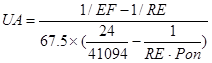
where
EF =The energy factor of the rated water heater (Unitless)
RE =The recovery efficiency of the rated water heater. If this data is not available the default shall be 0.78 for gas water heaters and 0.93 for electric water heaters.
Pon =The input power to the water heater, in Btu/h
Standard Design
The baseline loss coefficient for NAECA water heaters shall be:
10 Btu/h-F for gas-fired water heaters
Off Cycle Parasitic Losses
Applicability
Water heater
Definition
The rate of parasitic losses, such as a pilot light or controls, when the water heater is not heating.
Units
Watts
Input Restrictions
As designed
Standard Design
0
Off Cycle Fuel Type
Applicability
Water heater
Definition
The type of fuel that serves energy using parasitic equipment, such as a pilot light or controls, when the water heater is not heating.
Units
List: Electricity, Gas, Oil, Propane
Input Restrictions
As designed
Standard Design
Not applicable
On Cycle Parasitic Losses
Applicability
Water heater
Definition
The rate of parasitic losses, such as a pilot light or controls, when the water heater is not heating. This may be different than off cycle losses if the flue energy is considered.
Units
Watts
Input Restrictions
As designed
Standard Design
0
On Cycle Fuel Type
Applicability
Water heater
Definition
The type of fuel that serves energy using parasitic equipment, such as a pilot light or controls, when the water heater is not heating.
Units
List: Electricity, Gas, Oil, Propane
Input Restrictions
As designed
Standard Design
Electricity
Water Heater Ambient Location
Applicability
Water heater
Definition
The location of the water heater for determining losses and energy interaction with the surroundings
Units
List: Schedule, Zone, Outdoors
Input Restrictions
As designed
Standard Design
Zone
Tank Standby Loss Fraction
Applicability
Title 24 Standards
Definition
The tank standby loss fraction for storage tanks.
Units
Unitless
Input Restrictions
Prescribed to the value listed in the Commission’s Appliance Database of Certified Water Heaters
Standard Design
Not applicable
The part-load curve procedure in Title 24 can be an alternate method of specifying the effects of standby and parasitic losses on performance. The primary method is to specify a loss coefficient for the storage tank.
Fuel Water Heater Part Load Efficiency Curve
Applicability
Water Heating equipment for which a loss coefficient is not specified (alternate method)
Definition
A set of factors that adjust the full-load thermal efficiency for part load conditions. The factor is set as a curve.
Units
Percent (%)
Input Restrictions
The following prescribed curve shall be used based on user inputs. The curve shall take the form of a quadratic equation as follows:
(58)
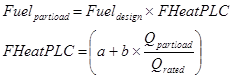
where
FHeatPLC The fuel heating part load efficiency curve
Fuelpartload The fuel consumption at part load conditions (Btu/h)
Fuel design The fuel consumption at design conditions (Btu/h)
Qpartload The water heater capacity at part load conditions (Btu/h)
Qrated The water heater capacity at design conditions (Btu/h)
For Title 24, the coefficients shall be determined by the following :
a = STBY / INPUT
b = INPUT

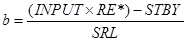
* or Thermal Efficiency (TE)
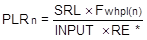
PLRn = Part-load ratio for the
nth hour and shall always be less than 1. PLR n
is
calculated from the following equation:
* or Thermal Efficiency (TE)
INPUT = The input capacity of the water heater expressed in Btu/hr.
STBY = Hourly standby loss expressed in Btu/hr. For large storage gas water heaters STBY is listed in the CEC’s appliance database. The value includes pilot energy and standby losses. For all other systems refer to equation N2-62.
SRL = the Standard Recovery Load, taken from Appendix 5.4A, in Btu/hr, adjusted for the number of occupants according to the occupancy schedules.
For Boilers, Instantaneous gas or other storage type water heaters, not in the scope of Covered Consumer Products as defined in the Title 10 or the Code of Federal Regulations, Part 430; STBY = 453.75 × S × VOL
where
S =The standby loss fraction listed in the Commission’s Appliance Database of Certified Water Heaters,
VOL =The actual storage capacity of the water heater as listed in the Commission’s Appliance Database of Certified Water Heaters,
Required inputs and standard and proposed design assumptions depend on the type of water heater and whether or not it is a DOE covered consumer product.
Standard Design
Not applicable
5.9.1.3 Recirculation Systems
This section describes the building descriptors for hot water recirculation systems. The baseline building has a recirculation system when the proposed design does. This is one aspect of the water heating system configuration (see above).
Recirculating systems shall follow the rules set forth in Appendix E of the 2013 Residential ACM Manual.
5.9.1.4 Water Heating Auxiliaries
External Storage Tank Insulation
Applicability
All water heating systems that have an external storage tank
Definition
Some water heating systems have a storage tank that is separate from the water heater(s) that provides additional storage capacity. This building descriptor addresses the heat loss related to the external tank, which is an additional load that must be satisfied by the water heater(s).
Units
R-value (h-ft2-F/Btu)
Input Restrictions
As specified in manufacturer data and documented on the construction documents
Standard Design
Heat loss associated with the storage tank in the baseline building shall meet the requirements for an unfired storage tank in the baseline standards which is an insulation R-value of 12.5. The surface area and location of the storage tank shall be the same as the proposed design.
External Storage Tank Area
Applicability
All water heating systems that have an external storage tank
Definition
Some water heating systems have a storage tank that is separate from the water heater(s) that provides additional storage capacity. This documents the entire exterior surface area of the tank.
Units
ft2
Input Restrictions
As specified in manufacturer specifications
Standard Design
Not applicable
External Storage Tank Location
Applicability
All water heating systems that have an external storage tank
Definition
Location of the storage tank, used to determine the heat loss rate and energy exchange with the surroundings
Units
List: Schedule, Zone, Outdoors
Input Restrictions
As designed
Standard Design
Not applicable
Heat Recovery
Applicability
Water heating systems that are coupled to heat recovery equipment
Definition
Building equipment such as air conditioners, chillers, gas fired generators, etc. produce thermal energy that may be recovered and used to heat water. The heat producing characteristics are generally defined for the equipment that is producing the heat, not the equipment that is receiving the heat (water heaters in this case). The building descriptors will vary depending on the equipment. The models for heat producing equipment need to produce output on an hourly basis so that the schedule of heat production and heating needs can be aligned and evaluated in the water heating model.
Units
Data structure: depends on the equipment producing the heat
Input Restrictions
There are no restrictions, other than agreement with the construction documents.
Standard Design
Not applicable
Solar Thermal
Applicability
Water heating systems with a solar thermal system
Definition
A solar thermal water heating system consists of one or more collectors. Water is passed through these collectors and is heated under the right conditions. There are two general types of solar water heaters: integrated collector storage (ICS) systems and active systems. Active systems include pumps to circulate the water, storage tanks, piping, and controls. ICS systems generally have no pumps and piping is minimal.
Solar systems may be tested and rated as a complete system or the collectors may be separately tested and rated. SRCC OG-300 is the test procedure for whole systems and SRCC OG-100 is the test procedure for collectors. The building descriptors used to define the solar thermal system may vary with each software application and with the details of system design.
The solar fraction shall be estimated by the f-chart procedure for solar water heating systems.
Units
Unitless fraction
Input Restrictions
The solar fraction provided by the solar DHW system shall be between 0 and 1.
Standard Design
The baseline building has no solar auxiliary system.
Combined Space Heating and Water Heating
Applicability
Projects that use a boiler to provide both space heat and water heating
Definition
A system that provides both space heating and water heating from the same equipment, generally the space heating boiler. Such systems are restricted by the baseline standards, but may be modeled in the candidate building. The restrictions are due to the misalignment of the space heating load and the water heating load. The first is highly intermittent and weather dependent, while the latter is more constant and not generally related to the weather.
Units
Data structure
Input Restrictions
The proposed design may have a combined space and water heating system.
Standard Design
The baseline building shall be modeled with separate space heating and water heating systems
Outdoor lighting requirements are specified in Standards section 140.7. Outdoor lighting shall not be modeled in the proposed design or standard design, and no tradeoffs are available with other building end uses or systems. Outdoor lighting shall meet all prescriptive requirements in the Standards. Compliance software shall accept user input for outdoor lighting and verify that the proposed design outdoor lighting does not exceed the standard design outdoor lighting, and shall include verification of compliance on the appropriate compliance form(s).
Swimming pools must meet applicable mandatory requirements and are not required to be modeled for California Title 24 compliance or Reach.
This set of building descriptors should be used to include any miscellaneous electricity use that would add to the electric load of the building and would be on the building meter. These energy uses are assumed to be outside the building envelope and do not contribute heat gain to any thermal zone.
Miscellaneous Electric Power
Applicability
All buildings with miscellaneous electric equipment located on the building site
Definition
The power for miscellaneous equipment.
Units
Watts (W)
Input Restrictions
As designed.
Standard Design
Same as the proposed design
Miscellaneous Electric Schedule
Applicability
All buildings with miscellaneous electric equipment located on the building site
Definition
The schedule of operation for miscellaneous electric equipment. This is used to convert electric power to energy use.
Units
Data structure: schedule, fractional
Input Restrictions
The schedule specified for the building should match the operation patterns of the system.
Standard Design
Same as the proposed design
This set of building descriptors should be used to include any miscellaneous gas use that would add to the load of the building and would be on the building meter. These energy uses are assumed to be outside the building envelope and do not contribute heat gain to any thermal zone.
Other Gas Power
Applicability
All buildings that have commercial gas equipment
Definition
Gas power is the peak power which is modified by the schedule (see below).
Units
Btu/h-ft²
Input Restrictions
As designed
Standard Design
Same as the proposed design
Other Gas Schedule
Applicability
All buildings that have commercial gas equipment
Definition
The schedule of operation for commercial gas equipment. This is used to convert gas power to energy use.
Units
Data structure: schedule, fractional
Input Restrictions
Continuous operation is prescribed.
Standard Design
Same as the proposed design