This is a new Section. It makes the recommended voltage drop limits from the California Electrical Code (Title 24 Part 3) mandatory. Specifically,
•The voltage drop in feeders is limited to 2% of design load; and
•The voltage drop in branch circuits is limited to 3% of design load.
Emergency power circuits are exempt.
Voltage drop represents energy loss as heat in the electrical conductors. The loss is called “I2R” (I-squared-R) loss, meaning that the loss is directly proportional to the conduction resistance and proportional to the amps squared. Because of I2R loss, it is advantageous to distribute utilization power at the highest practical voltage to reduce current to each load. This basic consideration will continue to promote 277/480-volt systems wherever practical. But with the growth of 120-volt utilization loads, many projects will consider 120/208-volt or 120/240-volt systems to avoid subtransformers and the added costs of having two power systems.
Once the distribution and utilization voltage(s) are determined, feeders and branch circuits are designed. Per code, the wire size or gauge is primarily based on “ampacity”, the number of amps for which the wire is rated in the application. Voltage drop limits may cause increased cable diameter (gauge), particularly for long wire runs.
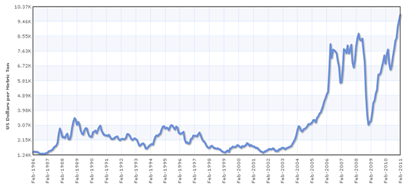
With rising prices of copper and the heavy demand for it in developing countries, there will be continued pressure to use aluminum alloy and copper clad aluminum for typical projects in the US. Past problems with aluminum branch circuits will discourage aluminum branch wiring, but feeders will use increasing amounts to save both cost and weight. Unfortunately, the resistivity of copper is 10.4 ohms per circular mil per foot as compared to 15% copper-clad aluminum (16.1) and AA-8000 series aluminum alloy (17.0). In practice, larger gauge aluminum and copper clad aluminum conductors will be required to reduce the voltage drop.
|
Source: Wikipedia
Voltage drop losses are cumulative, so that 2% loss in feeders and 3% loss in branch circuits add up to 5% loss relative to the load at the end of the branch circuit. Because electrical loads are not constant, the calculation is based on design load. For feeders, this is the calculated maximum demand load on the circuit per the California Electrical Code but does not include any of the additional ampacity required by the California Electric Code. For branch circuits, the design load is either (a) the branch circuit rating for receptacle loads (usually 16 amps), or (b) the 100% load of a specific load such as motor or fixed equipment.
The calculation is for the total length of the feeder, and for the maximum length of branch circuit to the load. For branch circuits, this calculation can be excessively complicated in many cases. For this reason, any of the following methods can be used to calculate branch circuit voltage drop:
a) A load-by-load, detailed calculation of the voltage drop. This is required for circuits with specific loads such as motors or fixed equipment.
b) For circuits with many loads such as receptacles, determine the approximate centroid of the load. The centroid is defined as the weighted center of all possible load locations. For a receptacle or lighting circuit, it is the physical center of the room or all rooms served by the circuit. Determine the voltage drop at that point for the actual load or 75% of the maximum allowable circuit amps, whichever is greater.
c) For circuits as b) but with a common neutral and multiple phase conductors carried as far as a first major junction box, the voltage drop calculated above may be reduced 25% to account for the cancelation of neutral current before the neutral is tapped and single phase circuits begin.
While voltage drop calculations can be performed by hand, they are also the output of most modern power design computer programs. 'In 'addition there are handy calculators on the Internet and procedures for determining voltage drop are printed in electrician’s handbooks.
Calculations are relatively straightforward. Multiply the allowed voltage-drop percentage (2% for feeders, 3% for branch circuits) by the nominal system voltage. This is the allowed drop in the feeder or branch circuit. Note to be careful whether calculating voltage drop in a single-phase or three-phase system, as illustrated in the following example.
Example 8-6
In a 120/208 volt system, the allowed voltage drop for a single phase 120 volt branch circuit load is (120 *.03) = 3.6 volts. For the feeder in the same 120/208 volt three phase system, the allowed voltage drop is (120*.02) = 2.4 volts, for a cumulative loss of 6 volts (5%).
Next, calculate the actual voltage drop in the circuit. Multiply the resistance times the length of wire in the circuit. Remember, the length of wire is TWICE the distance, as current must flow to the load and back. For three phase circuits, the allowed voltage drop is based on line-to-line volts, not line-to-neutral volts.
Example 8-7
In a 120/208 volt system, a single-phase branch circuit runs 100 feet to the centroid of a number of receptacles. Assuming 12 amps (75% of the maximum allowed load) and cooper wire, the voltage drop in the branch circuit will be
With #12 wire @ .00187 ohms/ft, Edrop = IR = 12*100*2*.00187 = 4.48 volts
With #10 wire @ .00118 ohms/ft, Edrop = IR = 12*100*2*.00118 = 2.81 volts
With #8 wire @ .000739 ohms/ft, Edrop = IR = 12*100*2*.000739 = 1.76 volts
In this case, the branch circuit should be #10 to the first load or junction box. The remainder of the circuit could probably be wired with #12 gauge provided there are no long runs or single large loads.
Example 8-8
A service panel feeds a 120/208 volt three phase panelboard 150 feet away. The design load is 80 amps, three-phase. The panel mains and feeder breaker are rated 100 amps. By code the feeder must be at least #3 AWG copper, but the more common size #2 AWG is used. Does it comply?
For #2 AWG, E = IR = .000513 ohms/ft *150 ft *2* 80 amps =12.3 volts. But the allowed drop is 208 * .02 = 2.4 volts. The answer is no, there will be too much loss in the feeder.
The proper feeder will be at least 400 MCM copper to achieve 2.4 volts or less in voltage drop.
Voltage drop calculations are of two principal types:
•Voltage drop in feeders, which are conductors carrying current from one switchboard or panelboard to another; and
•Voltage drop in branch circuits, which are conductors carrying current from a switchboard or panelboard to one or more connected loads.
As a general rule, “switchboards” include service entrance or disconnecting gear with or without distribution sections, power distribution gear of switchboard construction and employing feeder and/or branch circuit distribution breakers or fusible disconnects, motor control centers with motor starters and/or distribution breakers or fusible disconnects, and similar equipment. “Panelboards” include service entrance or disconnecting gear with or without distribution sections, power distribution gear of panelboard construction and employing feeder and/or branch circuit distribution breakers, and similar equipment.
A. Determining Load Current
For the purposes of voltage drop calculations, loads must be included as volt-amperes (VA), not watts. Because of the increased use of electronic equipment, unity power factor should not be assumed. For the purposes of this calculation, if power factor is known, the following power factors can be used to determine VA and thereby, circuit amps.
For instance, the minimum allowed power factor (pf) for an Energy Star LED lamp is 70% (0.7). Assume a lamp rated at 12 watts at 120 volts. The volt-amps will be
VA = Watts/pf
In this case, the VA will be (12/.7) = 17.14 VA and the current at 120 volts will be about .143 amps. This means that a maximum of (16/.143) = 111.8 lamps can be placed on a standard 20 amp circuit. If watts had been used instead of VA, the designer or electrician would have assumed that 160 lamps could be used on a circuit, which would have then drawn nearly 23 amps and tripped the breaker.
In an ideal world, the watts and VA of a load would be equal (pf = 1.0 or 100%). But many LED lighting and electronic branch circuit loads have poor power factor (80% or less). Poor power factor means that the load draws current but does not use all of the power, in essence storing the energy and returning it to the circuit unused. This causes inefficiency as the unused energy still causes power losses in transformers, conductors and other system components. Moreover, many utility tariffs charge customers extra for poor power factor.
|
Load Type |
Default Power Factor at 120 volts |
Default Power Factor at 277 volts |
Note |
|
Fluorescent lighting |
0.95 |
0.95 |
------ |
|
Compact fluorescent lighting |
0.9 (hardwired) 0.5 (GU-24) |
0.9 (hardwired) 0.3 (GU-24) |
NPF magnetic ballasts use GU-24 values |
|
LED lighting |
0.7 |
0.5 |
May be higher if specifications call for high power factor drivers |
|
Incandescent lighting |
1.0 |
1.0 |
------ |
|
HID lighting |
0.9 |
0.9 |
May be lower if NPF ballasts are specified |
|
HVAC packages |
0.85 |
0.9 |
------ |
|
Other motors <5 HP |
0.8 |
0.8 |
------ |
|
Other motors >5 HP |
0.85 |
0.85 |
------ |
|
Kitchen equipment |
0.9 |
N/A |
------ |
|
Receptacles |
0.6 |
N/A |
For dedicated receptacles, may be rated according to the load |
|
Electric heating including hot water |
1.0 |
1.0 |
------ |
|
Other |
0.85 |
0.85 |
------ |
B. Resistance versus Impedance
The resistance of wire (R) is relatively constant and predictable based on material, stranded versus solid cable, and length. There are small variations due to temperature, but for the purposes of voltage drop calculations in building wiring, the resistance at 25°C is generally suitable.
On the other hand, the impedance of wire (Z) depends on many factors, including type of conduit (if any), whether the wires are twisted, and type of insulation. Moreover, in normal operating calculations (not short circuit calculations), the inductive reactance (XL) plays a small role in circuit impedance, and at 60 Hz, the capacitive reactance (XC) plays little role in circuit behavior. Moreover, in DC circuits neither XL nor XC matter except under transient and short circuit conditions. Because R is the dominant cause of voltage drop, use of wiring resistance only is acceptable for the purposes of these calculations.
C. Feeder Calculations
The approximate length of the feeder can be determined by examining the plans and estimating the route that the installing contractor will use. This estimate should include lateral and vertical conduit lengths, with routing at right angles to the building structure. Diagonal routing may be used for calculations only if indicated on the plans. Note that this estimate should take into account any known conditions shown on the plans, and accuracy of 10% or better is considered acceptable.
The calculation should assume the design load per connected panelboard or switchboard load calculations. This means that the schedule for every panel should be shown on the plans, with circuit VA loads determined according to the California Electrical Code. The voltage drop should be based on the load and is not required to include derating factors. However, if spare feeder or branch circuit overcurrent protection devices or future spaces are provided in the connected panelboard or switchboard, then they are typically assumed to be loaded to 50% of rating. However, in any event the load of the connected panelboard or switchboard must not exceed its full rated load. .
If detailed load schedules are not available, or simply for ease of calculations, the voltage drop for the feeder may assume the connected panelboard or switchboard to being operated at 80% of rated ampacity. For example, for the feeder to a 400 amp panelboard, it is acceptable to assume (400*.8) = 320 amps.
Example 8-9
Feeder calculations
Basic Calculation
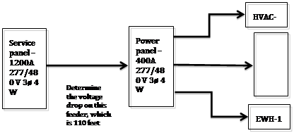
A service switchboard feeds a 277/480 volt 400 amp distribution panelboard (power panel) with the following schedule of devices and loads:
Section 1 - 200-amp three phase breaker – feeds rooftop HVAC unit rated 125 full load amps (FLA) with 500 locked rotor amps (LRA), minimum breaker size 175 amps
Section 2 – 100A three-phase breaker – feeds downstream 100A lighting panelboard with 65-amp three-phase connected load and no spare breakers.
Section 3 – (3) 20-amp single-phase breakers feeding local lighting loads of 12 amps, 8 amps and 10 amps, respectively
Section 4 – (1) 60-amp three-phase breaker feeding an electric water heater rated 18 kW and 43 amps per phase
This example includes a number of common load types and considerations.
•Section 1: for the feeder voltage drop calculation, full load amps (FLA) are to be used. The load on the feeder is 125-amps, three-phase.
•Section 2: for the feeder voltage drop calculation, the lighting load of 65-amps, three-phase is used at 100%.
•Section 3: for the feeder voltage drop calculation, the largest single-phase current is assumed for all three phases, or 12 amps at 100%.
•Section 4: for the feeder voltage drop calculation, the three-phase load of the water heater is (18,000 watts)*1.0 = 18 KVA, or (18KVA/.832) = 21.6 amps.
•The total maximum connected load amps is (125+65+12+22) = 224 amps.
The engineer specifies (2) 4/0 aluminum 90°C wire (rated 205 amps) aluminum per phase. The resistance of 4/0 stranded aluminum wire is .08360 ohms per 1000 feet at 25° C, so the resistance of two conductors per phase is (.08360/2) = .04180 ohms per 1000 feet. The maximum permissible voltage drop (line to line) is 480 volts * .02 = 9.6 volts.
The total circuit length (line-line) is 110 feet *2 = 220 ft. The circuit voltage drop is
E = IR = Amps x Resistance per 1000’ x length(ft)/1000 =
224 * .04180 * .220 = 2.1 volts (passes the test)
Spares and Spaces Calculation
Now assume that the power panel above has the following spares and spaces:
•Section 5 – 60-amp three-phase spare
•Section 6 – 100-amp three-phase space
These are typically counted at 50% load (or greater). This means that the new total load for the panel is (100+60)*.5 = 80 amps. The new total load is 224 amps (as determined above) plus 80 amps for a total of 304 amps.
Repeating the calculation above, the voltage drop in the specified (2) #4/0 aluminum conductors per phase is
E = IR = 304 * .04180*.220 = 2.8 volts (passes the test)
Ampacity Rating
For simplicity or when loads are not known, it is permissible to use 80% of the panel’s rated current. The power panel is rated at 400 amps three-phase, so the load to be used is 400*.8 = 320 amps. The voltage drop is
320* .04180*.220 = 2.9 volts (passes the test)
In order to expedite design, as an alternative to performing detailed calculations, Table 130.5-B allows the selection of acceptable combinations of feeder conductors and distance meeting these voltage-drop requirements.
D. Branch Circuit Calculations
Branch circuits provide power from switchboards, panelboards or other distribution centers to individual loads or groups of loads. An example of an individual load is a rooftop package HVAC unit, which although technically is a group of loads including a compressor, fan, control circuits, etc., it is all in one place and the manufacturer provides the total load amps for the package unit. An example of a group of loads is a lighting branch circuit, to which a large number of individual loads might be connected over a large area.
As a general rule for individual loads, the location of the load is known. First determine the length of the branch circuit, taking into account both the lateral and vertical distance from power source to load. Conduit routing is usually at right angles to the building structure unless specifically shown on the plans. Next, determine the branch circuit voltage drop assuming 100% of rated load, calculated per the California Electrical Code. Derating factors used to determine current amps and conductor size do not need to be included.
As a general rule for branch circuits with multiple loads, in plan identify all loads on the circuit. Determine the centroid of the loads on the circuit, which is defined as the weighted central location of the group of loads. It is usual to determine the approximate location of the centroid of the loads simply by “judging by eye”. The length of the branch circuit is defined as the distance from this point to the power source. Assume conduit routing at right angles to the building structure unless specifically shown on the plans. Next, determine the branch circuit voltage drop; this can be based on the following load factors, calculated per the California Electrical Code. Derating factors used to determine current amps and conductor size do not need to be included. Note that since the intent of this calculation is to determine the voltage drop that is primarily contained in the home-run conductors with an approximation for tap conductors, this method can be used for any wiring method.
|
Load type |
Percentage of Code connected load to be used |
Notes and Special Exceptions |
|
Lighting |
100% |
|
|
Receptacles |
75% |
100% of all equipment loads using cord and plug connection |
|
Combined lighting and receptacle |
100% of lights and 75% of receptacles |
------ |
|
Tapped circuits |
75% of receptacles 100% of all other loads |
For circuits tapped downstream to supply mixed loads |
Note: as a convenience, the calculation may assume the allowed branch circuit capacity. In general, this is 80% of the rating of the overcurrent protection device, e.g. 16 amps for a 20-amp circuit. This is especially recommended for lighting and receptacle branch circuits that might have additional loads connected later.
Example 8-10
Single Load Example
A package HVAC unit running on 208 volts, three-phase has a full load amp (FLA) rating of 10.5 amps and locked rotor amps (LRA) of 45 amps. The engineer specified #12 wires and a 20 amp 3-pole breaker. The physical distance is 200 feet. What is the voltage drop and does it meet section 130.5?
On a 208 volt line-to-line circuit, the allowed branch circuit voltage drop is 3%, or (208*.03) = 6.24 volts.
The resistance of solid copper #12 wire is 1.62 ohms/1000 ft at 25° C. The voltage drop in this circuit is:
E = IR = 10.5*1.62 *(400/1000) = 6.84 volts (fails)
This circuit will require #10 wires.
Example 8-11
Centroid Example
90 LED troffers are located in an office space. Each troffer is an LED luminaire rated at 277 volts, 42 watts and .16 amps, for a total of 14.4 amps for all 90 luminaires. The centroid is at the weighted center of all the luminaires, meaning the “center of mass”. An approximate location is likely to be sufficient for compliance purposes. In this example, the centroid is about 150 feet from the panel. What is the voltage drop and does it meet section 130.5?
On a 277 volt line to neutral circuit, the allowed branch circuit voltage drop is 3%, or (277*.03) = 8.31 volts.
The resistance of solid copper #12 wire is 1.62 ohms/1000 ft at 25° C. The voltage drop in this circuit is:
E = IR = 14.4*1.62 *(300/1000) = 7.00 volts (passes)
Note that the voltage drop is (7/277) = 2.5%. The engineer might be advised to use #10 home run conductors and tap down to #12 for the remainder of the branch circuit.
Example 8-12
Branch Circuit Rating Example
It is permissible to use 80% of the branch circuit overcurrent protection device as the circuit current. This method is strongly recommended for branch circuits to which additional loads might be added in the future.
For #12 wires, the overcurrent protection device is 20-amps, so the current to be used for the calculation is 20 amps * 0.8 = 16 amps. If the conduit length is 225 feet, what is the voltage drop and does it meet section 130.5?
On a 277 volt line to neutral circuit, the allowed branch circuit voltage drop is 3%, or (277*.03) = 8.31 volts.
The resistance of solid copper #12 wire is 1.62 ohms/1000 ft at 25° C. The voltage drop in this circuit is:
E = IR = 16*1.62 *(450/1000) = 11.64 volts (fails)
For #10 stranded conductors,
E = IR = 16*1.04 *(450/1000) = 7.84 volts (passes)
The engineer should choose #10 home run conductors and may consider tapping down to #12 for the remainder of the branch circuit.
|
Circuit Volts (V) |
2% Voltage Drop (V) |
3% Voltage Drop (V) |
Total Loss (V) |
|
120 |
2.4 |
3.6 |
6.0 |
|
208 |
4.2 |
6.2 |
10.4 |
|
240 |
4.8 |
7.2 |
12.0 |
|
277 |
5.5 |
8.3 |
13.9 |
|
480 |
9.6 |
14.4 |
24.0 |
|
Wire |
Circuit Amps |
Maximum Feeder Length |
Maximum Branch Circuit Length | ||||||||
|
120 |
208 |
240 |
277 |
480 |
120 |
208 |
240 |
277 |
480 | ||
|
14* |
12 |
39 |
67 |
78 |
90 |
156 |
58 |
101 |
117 |
135 |
233 |
|
12* |
16 |
46 |
80 |
93 |
107 |
185 |
69 |
120 |
139 |
160 |
278 |
|
10 |
24 |
48 |
83 |
96 |
111 |
192 |
72 |
125 |
144 |
166 |
288 |
|
8 |
32 |
57 |
99 |
115 |
132 |
229 |
86 |
149 |
172 |
199 |
344 |
|
6 |
40 |
73 |
127 |
146 |
169 |
293 |
110 |
190 |
220 |
253 |
439 |
|
4 |
52 |
89 |
154 |
178 |
206 |
356 |
134 |
232 |
267 |
309 |
535 |
|
2 |
72 |
103 |
178 |
206 |
237 |
412 |
154 |
267 |
309 |
356 |
617 |
|
0 |
96 |
123 |
212 |
245 |
283 |
490 |
184 |
319 |
368 |
424 |
735 |
|
00 |
108 |
137 |
238 |
274 |
317 |
549 |
206 |
357 |
412 |
475 |
823 |
|
0000 |
144 |
163 |
283 |
327 |
377 |
654 |
245 |
425 |
490 |
566 |
980 |
|
250 |
164 |
170 |
294 |
340 |
392 |
679 |
255 |
441 |
509 |
588 |
1019 |
|
300 |
184 |
181 |
314 |
362 |
418 |
725 |
272 |
471 |
543 |
627 |
1087 |
|
350 |
200 |
195 |
338 |
390 |
450 |
779 |
292 |
506 |
584 |
675 |
1169 |
|
500 |
248 |
224 |
388 |
448 |
517 |
896 |
336 |
582 |
672 |
776 |
1344 |
|
Wire |
Circuit Amps |
Maximum Feeder Length |
Maximum Branch Circuit Length | ||||||||
|
120 |
208 |
240 |
277 |
480 |
120 |
208 |
240 |
277 |
480 | ||
|
14* |
12 |
24 |
41 |
47 |
55 |
95 |
36 |
62 |
71 |
82 |
142 |
|
12* |
16 |
28 |
49 |
56 |
65 |
113 |
42 |
73 |
85 |
98 |
169 |
|
10 |
24 |
29 |
51 |
59 |
68 |
118 |
44 |
76 |
88 |
102 |
176 |
|
8 |
32 |
35 |
61 |
70 |
81 |
140 |
53 |
91 |
105 |
121 |
210 |
|
6 |
40 |
45 |
77 |
89 |
103 |
178 |
67 |
116 |
134 |
154 |
267 |
|
4 |
52 |
54 |
94 |
109 |
126 |
218 |
82 |
142 |
163 |
188 |
327 |
|
2 |
72 |
62 |
108 |
125 |
144 |
250 |
94 |
162 |
187 |
216 |
375 |
|
0 |
96 |
74 |
129 |
149 |
172 |
298 |
112 |
193 |
223 |
258 |
446 |
|
00 |
108 |
84 |
145 |
167 |
193 |
334 |
125 |
217 |
251 |
289 |
501 |
|
0000 |
144 |
99 |
172 |
198 |
229 |
397 |
149 |
258 |
298 |
344 |
595 |
|
250 |
164 |
103 |
179 |
207 |
239 |
413 |
155 |
269 |
310 |
358 |
620 |
|
300 |
184 |
111 |
192 |
221 |
255 |
442 |
166 |
287 |
332 |
383 |
663 |
|
350 |
200 |
119 |
206 |
238 |
274 |
475 |
178 |
309 |
356 |
411 |
713 |
|
500 |
248 |
137 |
237 |
273 |
316 |
547 |
205 |
355 |
410 |
473 |
820 |