Proposed design
The building is defined through entries for zones, surfaces, and equipment. Zone types include attic, conditioned space, crawl space, basements, and garages. The roof (such as asphalt shingles or tile) is defined as either part of the attic or as part of a cathedral ceiling (also called a rafter roof). Surfaces separating conditioned space from exterior or unconditioned spaces (such as garage or storage) are modeled as interior surfaces adjacent to the unconditioned zone. Exterior surfaces of an attached garage or storage space are modeled as part of the unconditioned zone.
The input file will include entries for floor areas, wall, door, roof and ceiling areas, and fenestration and skylight areas, as well as the water heating, space conditioning, ventilation, and distribution systems.
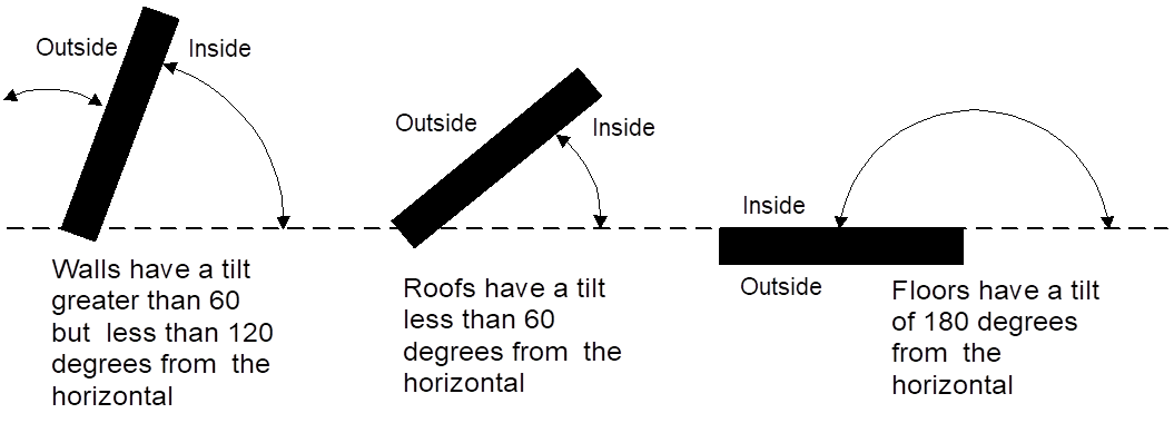
Each surface area is entered along with performance characteristics, including building materials, U-factor and SHGC. The orientation and tilt (see Figure 1) is required for envelope elements.
Building elements are to be consistent with the actual building design and configuration.
Standard Design
To determine the standard design for low-rise buildings, a building with the same general characteristics (number of stories, attached garage, climate zone) and with wall and window areas distributed equally among the four main compass points is created by the software. Energy features are set to be equal to §150.1(c) and Table 150.1-A. For additions and alterations, the standard design for existing features in the existing building shall have the same wall and fenestration areas and orientations as the proposed building. The details are described below.
Verification and Reporting
All inputs that are used to establish compliance requirements are reported on the CF1R for verification.
Proposed Design
The user specifies the climate zone based on the zip code of the proposed building. Compliance requirements, weather, design temperatures, and Time Dependent Valuation (TDV) of energy factors are a function of the climate zone. Compliance software assumes that the ground surrounding residential buildings has a reflectivity of 20 percent in both summer and winter.
Standard Design
The standard design climate zone is the same as the proposed design.
Verification And Reporting
The zip code and climate zone of the proposed design is reported on the CF1R for verification.
This input determines the appropriate federal appliance efficiency requirement for the standard design to compare with the proposed design.
Proposed Design
The user inputs Compliance2017.
Standard Design
The standard design cooling equipment efficiency is based on the federal requirements. A minimum SEER and EER (if applicable) that meet the current standard for the type of equipment is modeled.
Verification and Reporting
Compliance version is reported on the CF1R.
The compliance credit available for photovoltaic (PV) systems is available for new construction only and is dependent on the climate zone and dwelling unit size. The credit may be used to tradeoff any efficiency measure, with limits as described below. The PV system must meet the eligibility and verification requirements of Residential Appendix RA4.6.1 and must meet the minimum system size described below.
The PV compliance credit for both single- and multi-family buildings is calculated by the compliance software and is equal to:
PVcredit = TDVstd * PVmaxpct / 100.0 Equation 1
Where:
PVcredit = PV compliance credit (kTDV/ft2)
TDVstd = Standard Design Compliance Total (kTDV/ft2) PVmaxpct = Maximum PV Credit Percentage from Table 1
The minimum PV system size for compliance credit is calculated by the compliance software and is equal to:
PVminsize = ROUND((PVthreshold + PVaddedsize ) * Ndwellingunits, 1) Equation 2
For average dwelling units less than or equal to CFAthreshold:
PVaddedsize = 0 Equation 3
For average dwelling units larger than CFAthreshold:
PVaddedsize = PVcredit * (CFAdwellingunit – CFAthreshold) / PVgenerate Equation 4
The maximum PV credits in Table 1 are calculated by using a prototype analysis with the proposed features set equal to the 2016 prescriptive requirements except replacing the 2016 high performance attics (HPA) and high performance walls (HPW) with the 2013 prescriptive requirements. The percentages are calculated by dividing the compliance margin (kTDV/ft2) by the standard design compliance energy use (kTDV/ft2) and multiplying by -100. Climate zones 6 and 7 have no 2016 requirement for either HPA or HPW, so there is no PV credit in those climate zones.
PROPOSED DESIGN
The software allows the user to specify the use of PV compliance credit and establishes the minimum solar system in kilowatts direct current (DC). The software calculates the solar credit and subtracts it from the proposed design.
The standard design has no PV system.
VERIFICATION AND REPORTING
A solar credit is reported as a special feature on the CF1R.
|
Climate Zone |
PV Generation Rate(kTDV/kWdc) |
Maximum PV Credit for Single Family |
Maximum PV Credit for Multi Family |
|
01 |
26762 |
8.0% |
4.4% |
|
02 |
30021 |
8.6% |
5.0% |
|
03 |
31137 |
6.9% |
3.1% |
|
04 |
30935 |
17.7% |
11.4% |
|
05 |
33490 |
7.6% |
2.3% |
|
06 |
30081 |
0.0% |
0.0% |
|
07 |
30701 |
0.0% |
0.0% |
|
08 |
29254 |
28.1% |
9.1% |
|
09 |
29889 |
25.9% |
11.0% |
|
10 |
30200 |
23.1% |
10.0% |
|
11 |
29693 |
17.7% |
8.7% |
|
12 |
29328 |
22.0% |
9.5% |
|
13 |
29553 |
19.8% |
9.2% |
|
14 |
31651 |
16.0% |
8.2% |
|
15 |
29177 |
16.3% |
7.3% |
|
16 |
30930 |
15.1% |
8.6% |
|
Dwelling Type |
PV threshold (kWdc) |
CFA threshold (ft2) |
|
Single Family |
2.0 |
2000 |
|
Multi Family |
1.0 |
1000 |
These inputs are used for additions and alterations. The standard design assumption for existing conditions vary based on whether the existing conditions are verified by a home energy rating system (HERS) rater prior to construction. See Section 2.10.3 for more information.
PROPOSED DESIGN
The user inputs either yes or no. “Yes” indicates that the existing building conditions verified by a HERS rater. Default assumption is “no”.
STANDARD DESIGN
The standard design assumption is based on Section 150.2(b), Table 150.2-C If the user input is “no,” the standard design for the existing component is based on the value in the second column. If the proposed design response is “yes,” the standard design value for the existing components is the value in the third column.
Verification And Reporting
Verification of existing conditions is a special feature and is reported in the HERS required verification listings on the CF1R.
Air leakage is a building level characteristic. The compliance software distributes the leakage over the envelope surfaces in accordance with the building configuration and constructs a pressure flow network to simulate the air flows between the conditioned zones, unconditioned zones and outside.
2.2.5.1 Building Air Leakage and Infiltration (ACH50)
The air flow through a blower door at 50 Pascal (Pa) of pressure measured in cubic feet per minute is called cfm50. Cfm50 x 60 minutes divided by the volume of conditioned space is the air changes per hour at 50 Pa, called ACH50.
Specific data on ACH50 may be entered if the single-family building or townhouse will have verified building air leakage testing. In multi-family buildings, due to the lack of an applicable measurement standard, ACH50 is fixed at the above defaults.
Proposed Design
ACH50 defaults to 5 for new construction in single family buildings and townhomes and 7 for all other buildings that have heating and/or cooling system ducts outside of conditioned space, and for buildings with no cooling system. In single-family buildings and townhomes with no heating and/or cooling system ducts in unconditioned space the default ACH50 is 4.4 and 6.2 for all others.
Specific data on ACH50 may be entered if the single-family building or townhouse will have verified building air leakage testing. User input of an ACH50 that is less than the default value becomes a special feature that requires HERS verification.
Due to the lack of an applicable measurement standard, ACH50 is fixed at the above defaults and is not a compliance variable in multi-family buildings.
Standard Design
The standard design shall have 5 ACH50 for single family buildings and 7 for other buildings (ducted space conditioning).
Verification and Reporting
When the user chooses verified building air leakage testing (any value less than the standard design), diagnostic testing for reduced infiltration, with the details and target values modeled in the proposed design, is reported in the HERS required verification listing on the CF1R.
2.2.5.2 Defining Air Net Leakage
The compliance software creates an air leakage network for the proposed and standard design using the building description. Air leakage is distributed across the envelope surfaces according to the factors in Table 3. The air network is insensitive to wind direction. For buildings modeled with multiple conditioned zones, either a 20 square foot open door or 30 square foot open stairwell (in a multi-story building) is assumed between any two conditioned zones.
The only difference between the air network for the proposed and standard designs is the ACH50 if the user specifies a value lower than the default.
Multi-family buildings that have floors between dwelling units, must define each floor as a separate zone or each dwelling unit as a separate zone.
|
% of Total Leakage by Surface | ||||
|
Configuration |
Ceilings |
Floors |
Exterior Walls |
House to Garage Surfaces |
|
Slab on Grade |
50 |
0 |
||
|
Raised Floor |
40 |
10 |
||
|
No Garage |
50 |
0 | ||
|
Attached Garage |
40 |
10 | ||
The compliance software user may specify either standard (unverified) or improved (verified high quality insulation installation, also called quality insulation installation or QII)) for the proposed design. Buildings with standard insulation installation are modeled in the program with lower performing cavity insulation in framed walls, ceilings, and floors, and with added winter heat flow between the conditioned zone and attic to represent construction cavities open to the attic. (See Table 4.) Standard insulation does not affect the performance of continuous sheathing in any construction.
Proposed Design
The compliance software user may specify improved quality insulation installation at the building level. The default is unverified/standard insulation installation. See Section 2.3.3 for information on modeling spray foam insulation.
Standard Design
The standard design is modeled with standard insulation installation quality.
Verification and Reporting
The presence of improved/verified high quality insulation installation is reported in the HERS required verification listings on the CF1R. Improved quality insulation installation is certified by the installer and field verified to comply with RA3.5. Credit for verified quality insulation installation is applicable to ceilings/attics, knee walls, exterior walls and exterior floors.
|
Component |
Modification |
|
Walls, Floors, Attic Roofs, Cathedral Ceilings |
Multiply the cavity insulation R-value/inch by 0.7 |
|
Ceilings below attic |
Multiply the blown and batt
insulation R-value/inch by |
|
Ceilings below attic |
Add a heat flow from the conditioned zone to the attic of 0.015 times the area of the ceiling below attic times (the conditioned zone temperature - attic temperature) whenever the attic is colder than the conditioned space |
For alterations to existing pre-1978 construction, if existing wall construction is assumed to have no insulation, no wall degradation is assumed for the existing wall.
Proposed Design
The number of bedrooms in a building is used to establish the indoor air quality (IAQ) mechanical ventilation requirements and to determine if a building qualifies as a compact building for purposes of incentive programs.
Standard Design
The standard design shall have the same number of bedrooms as the proposed design.
Verification and Reporting
The number of bedrooms is reported on the CF1R for use in field verification.
Internal gains and indoor air quality (IAQ) ventilation calculations depend on the conditioned floor area and number of bedrooms. For multi-family buildings with individual IAQ ventilation systems, each combination of bedrooms and conditioned floor area has a different minimum ventilation cfm that must be verified. A dwelling unit type is one or more dwelling units in the building, each of which has the same floor area, number of bedrooms, and appliances.
Proposed Design
For each dwelling unit type the user inputs the following information:
•Unit name
•Quantity of this unit type in building
•Conditioned floor area (CFA) in square feet per dwelling unit
•Number of bedrooms
Standard Design
The standard design shall have the same number and type of dwelling units as the proposed design.
Verification and Reporting
The number of units of each type and minimum IAQ ventilation for each unit is reported on the CF1R for use in field verification.
The input for the building front orientation is the actual azimuth of the front of the building. This will generally be the side of the building where the front door is located. The orientation of the other sides of a building viewed from the outside looking at the front door are called front, left, right, back, or a value relative to the front, and the compliance software calculates the actual azimuth from this input. Multiple orientation compliance can be selected for newly constructed buildings only.
Proposed Design
The user specifies whether compliance is for multiple orientations or for a site-specific orientation. For site-specific orientation the user inputs the actual azimuth of the front in degrees from true north.
Standard Design
The compliance software constructs a standard design building that has 25 percent of the proposed model wall and window areas facing each cardinal orientation regardless of the proposed model distribution of wall and window area.
Verification and Reporting
A typical reported value would be "290 degrees (west)". This would indicate that the front of the building faces north 70° west in surveyors terms. The closest orientation on 45° compass points should be reported in parenthesis (for example: north, northeast, east, southeast, south, southwest, west, or northwest). When compliance is shown for multiple orientations, "all orientations" or “cardinal” is reported as a special feature on the CF1R and the energy use results are reported for four orientations including north, east, south, and west.
The user specifies whether natural gas is available at the site. This is used to establish the TDV values from Reference Appendices JA3 used by the compliance software in determining standard and proposed design energy use.
Proposed Design
The user specifies whether natural gas is available at the site. For newly constructed buildings, natural gas is available if a gas service line can be connected to the site without a gas main extension. For additions and alterations, natural gas is available if a gas service line is connected to the existing building.
Standard Design
The standard design TDV values for space heating are as defined in Section 2.4.1 and for water heating are as defined in Section 2.9.
Verification and Reporting
Whether natural gas is or is not available is reported on the CF1R.
The user specifies whether there is an attached garage. The garage zone is modeled as an unconditioned zone (see Section 2.8).
Proposed Design
The user specifies whether there is an attached unconditioned garage.
Standard Design
The standard design has the same attached garage assumption as the proposed design.
Verification and Reporting
Features of an attached garage are reported on the CF1R.
Details of the calculation assumptions for lighting loads are included Appendix C and are based on the Codes and States Enhancement Initiative (CASE) report on plug loads and lighting (Rubin 2016, see Appendix D).
Proposed Design
Fraction of portable lighting, power adjustment multiplier and the exterior lighting power adjustment multiplier (Watts/ft2 – Watts per square foot) are fixed assumptions.
Standard Design
The standard design lighting is set equal to the proposed design lighting.
Verification and Reporting
No lighting information is reported on the CF1R for compliance with Title 24, Part 6.
Details of the calculation assumptions for appliances and plug loads are contained in Appendix C and based on the Codes and States Enhancement Initiative (CASE) report on plug loads and lighting (Rubin 2016, see Appendix D).
Proposed Design
All buildings are assumed to have a refrigerator, dishwasher and cooking appliance. Optionally, buildings can have a clothes washer and clothes dryer. The user can select fuel type as gas or electric for the clothes dryer and cooking appliance.
Standard Design
The standard design appliances are set equal to the proposed appliances.
Verification and Reporting
No information for the appliance types listed above is reported on the CF1R for compliance with Title 24, Part 6
.