The Energy Commission encourages the use of energy-saving techniques and designs for showing compliance with the standards. Many standard products with traditional construction practices can be used in ways that improve building efficiency beyond requirements set by the standards. In addition, innovative construction techniques and building products are being used more often by designers and builders who recognize the value of energy–efficient, high-performance buildings. When the performance compliance method is used, an energy credit can be taken for design strategies that reduce building energy use below the standard design energy budget (compliance credit). Some strategies may require third-party verification by a HERS Rater, others do not.
Insulation is one of the least expensive measures to improve building energy efficiency. Insulation requires no maintenance, helps improve indoor comfort, and provides excellent sound control. Adding extra insulation at a later time is much more expensive than maximizing insulation levels at the beginning of construction. General insulation types are discussed below.
Documentation of insulation R-values and assembly U-factors includes product data sheets, manufacturer specifications and installation guidelines, insulation product and assembly testing information, and U-factor calculations following the procedures specified in JA4, or from results of approved performance compliance computer software. The third-party HERS Rater shall verify that all insulation has been installed properly and is integral with the air barrier being used throughout the building.
There are four basic types of insulation, or insulation "systems," installed in residential buildings and the use varies based on the design and type of construction:
1. Batt and Blanket: Batt and blanket insulation is made of mineral fiber and mineral wool − either processed fiberglass, rock, or slag wool; natural wool products—animal wool or cotton-based products; or cellulose materials. These products are used to insulate below floors, above ceilings, below roofs, and within walls. They offer ease of installation with R-values set by the manufacturer based on size and thickness. They are available with facings, some as vapor retarders, and have flanges to aid in installation to framed assemblies. They also are available as unfaced material and can be easily friction-fitted into framed cavities.Batt and blanket insulation allow easy inspection and installation errors can readily be identified and remedied, including breeches in the air barrier system that allow air leakage. Nevertheless, care should always be taken to install the insulation properly, filling the entire cavity, and butting ends or sides of the batt material to ensure uniformity of the installation. Batt and blanket insulation material must be split to allow for wiring, plumbing, and other penetrations within the framed cavity.
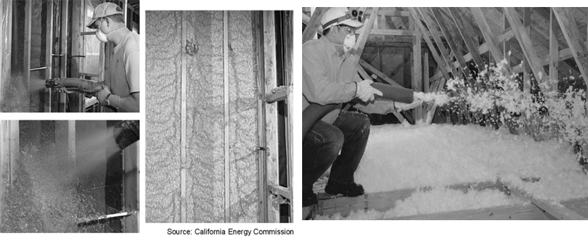
2. Loose-Fill Insulation: There are several commonly used types of insulation that have a pneumatic or blown installation process, including cellulose, fiberglass, and natural wool (animal- or cotton-based products). Blown wall insulation can be an effective way to deal with the irregularities of wall cavities, especially the spaces around pipes, electric cables, junction boxes, and other equipment that is embedded in cavities. (See Figure 3-50A.) The R-value of blown wall insulation material installed in closed cavities is determined by the installed thickness. This differs from manufactured products such as fiberglass or mineral wool batts for which the R-value has been tested and arrives at the construction site in preformed lengths and thicknesses with set R-value thicknesses.
When installed in floors, walls, and other vertical assemblies, these fibrous insulations are held in place in one of three ways:
1. Pre-installed netting or fabric
2. Use of existing cavity walls
3. Use of integral adhesives
Blown wall insulation installed in closed cavities must be thoroughly checked for density (or coverage) to ensure the R-value is achieved. A line of sight down a wall section can deceivingly hide imperfections in the installation, leading to underachieving stated R-values. Depressions and voids within the insulated cavity are areas lacking in R-value performance. Where netting is used, overspraying can result in a higher installed density (higher R-value) but can be troublesome for attaching gypsum board to wall framing. Where cavities have been underfilled, there may be voids or “soft” areas under the netting. These areas are often refilled, or the area is removed of insulation material and a thermal batt is installed in its place.
When installed in open surfaces, such as an attic floor or open wall, no netting or preexisting wall cladding is needed. (See Figure 3-50B.) In open horizontal applications, such as attic floors, no adhesives are used, and the R-value is verified by thickness and rated coverage. In open vertical applications, integral adhesives are used to hold the fibers in place. Water-activated adhesives are used for moist-spray cellulose, and polymer adhesives are used for fiberglass loose-fill applications. The adhesive causes the insulation to adhere to itself and stick to surfaces of the wall cavity. Excess insulation that extends past the wall cavity is scraped off and recycled. R-value is depends on the installed density of the material at the building site and the building official should ensure that the installed density meets manufacturer specifications.
3. Spray Polyurethane Foam (SPF)
SPF is a two-part, liquid-foamed thermoset plastic (such as polyurethane). Polyurethane is formed by the reaction of an isocyanate and a polyol. Blowing agents, catalysts, and surfactants are added to develop a cellular structure before the polyurethane mixtures cures. When this mixture is applied to substrate materials, the SPF material forms in place to provide insulation, an air seal, and, in the case of closed-cell SPF, an integral vapor retarder and water barrier.
SPF insulation is a two-component reactive system mixed at a spray gun or a single-component system that cures by exposure to humidity. The liquid is sprayed through a nozzle into the wall, roof/ceiling, and floor cavities. SPF insulation can be formulated to have specific physical properties (such as density, compressive strength, fire resistance, and R-value).
SPF insulation is spray-applied to adhere fully to the joist and other framing faces to form a complete air seal within the construction cavities. SPF must be separated from the interior of the building, even attic spaces, by an approved thermal barrier consisting of ½-inch (12.7 mm) gypsum wallboard or equivalent thermal barrier material (Section 316.4, CBC).
There are two types of SPF insulation:
a. Low-Density Open-Cell SPF (ocSPF) Insulation: A spray-applied polyurethane foam insulation having an open cellular structure resulting in an installed nominal density of 0.4 to 1.5 pounds per cubic foot (pcf), ocSPF has been assigned a default R-value of 3.6 per inch for compliance purposes, but some products can achieve higher R-values. The ocSPF insulation is sprayed then expands to fill the framed cavity. (See Figure 3-51.) Excess insulation is removed with a special tool. The average thickness of the foam insulation must meet or exceed the required R-value. Depressions in the foam insulation surface shall not be greater than 1 inch of the required thickness, provided these depressions do not exceed 10 percent of the surface area being insulated. The ocSPF must fill the cavity of 2x4 framing to achieve R-13.
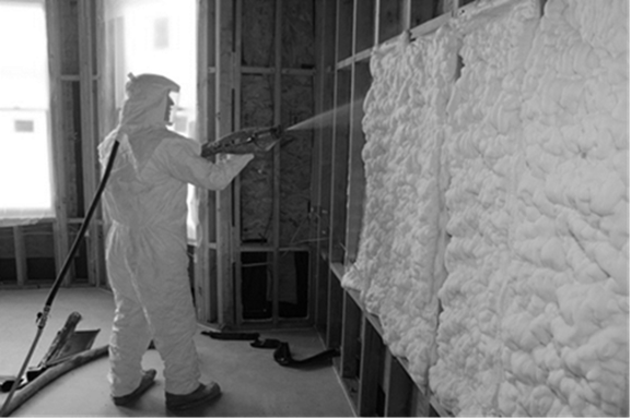
Source: SPFA
b. Medium-Density Closed-Cell SPF (ccSPF) Insulation: A spray-applied polyurethane foam insulation having a closed cellular structure resulting in an installed nominal density of greater than 1.5 to less than 2.5 pounds per cubic foot (pcf), ccSPF has been assigned a default R-value of 5.8 per inch for compliance, but some products can achieve higher R-values. The average thickness of the foam insulation must meet or exceed the required R-value. Depressions in the surface of the foam insulation shall not be greater than ½-inch of the required thickness at any given point of the surface area being insulated. CcSPF is not required to fill the cavity. (See Figure 3-52.)
SPF R-value depends on the installed thickness, and the building official should ensure the thickness and uniformity of the SPF material within each cavity of framed assemblies meets manufacturer specifications. Default R-values assigned to SPF are shown in Table 3-9.
|
Thickness of SPF Insulation |
R11 |
R13 |
R15 |
R19 |
R21 |
R22 |
R25 |
R30 |
R38 |
|
Required thickness of ccSPF Insulation (inches) |
2.00 |
2.25 |
2.75 |
3.50 |
3.75 |
4.00 |
4.50 |
5.25 |
6.75 |
|
Required thickness of ocSPF Insulation (inches) |
3.00 |
3.50 |
4.20 |
5.30 |
5.80 |
6.10 |
6.90 |
8.30 |
10.6 |
Alternatively, the total R-value may be calculated based on the thickness of insulation multiplied by the "tested R-value per inch" as 'listed in the Table of R-values or R-value Chart from the manufacturer's current ICC Evaluation Service Report (ESR) that shows compliance with Acceptance Criteria for Spray-Applied Foam Plastic Insulation-AC377. Overall assembly U-factors are determined by selecting the assembly type, framing configuration, and cavity insulation rating from the appropriate JA4 table, other approved method specified in JA4 or using the Energy Commission-approved compliance simulation software.

Source: SPFA
4. Rigid Insulation: Rigid board insulation sheathing is made from fiberglass, expanded polystyrene (EPS), extruded polystyrene (XPS), polyisocyanurate (ISO), or polyurethane. It varies in thickness, and some products can provide up to R-6 per inch of thickness.
This type of insulation is used for above-roof decks, exterior walls, cathedral ceilings, basement walls, as perimeter insulation at concrete slab edges, and to insulate special framing situations such as window and door headers, and around metal seismic bracing. Rigid board insulation may also be integral to exterior siding materials. Properly sealed rigid insulation can be used continuously across an envelope surface to reduce air infiltration and exfiltration, and thermal bridging at framing.
The Department of Energy Building America website contains regularly updated information on proper continuous rigid insulation installation, including recommendations for button cap nails, furring strips, flashing, and design of the drainage plane. An image showing proper rigid insulation installation is shown in Figure 3-53.

Source: U.S. Environmental Protection Agency
The 2015 California Residential Code (CRC) provides guidance on fastener penetration depth, diameter, and spacing for exterior foam sheathing in Section R703.11.2. CRC Table 703.15.1 , reproduced below in Figure 3-54, shows the fastener spacing for cladding attachment over foam sheathing to wood framing.
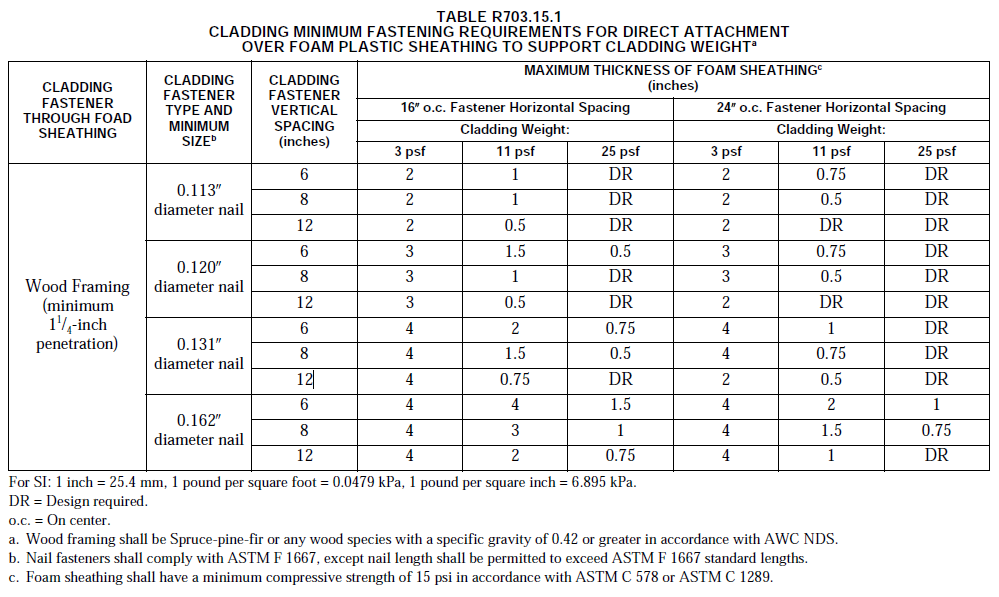
Source: 2015 International Residential Code
Mass walls typically fall into two categories:
1. Masonry types include clay and concrete units, which may be solid or hollow, and glazed or unglazed. Other masonry unit types include cast stone and calcium silicate units. Concrete masonry units (CMU) are made from a mixture of Portland cement and aggregates under controlled conditions. Concrete masonry units can be manufactured in different sizes and with a variety of face textures.
2. Concrete and concrete sandwich panels typically use a precast form by casting concrete in a reusable mold or "form" that is then cured in a controlled environment, transported to the construction site, and lifted into place. Precast stone is distinguished from precast concrete by using a fine aggregate in the mixture, giving the appearance of naturally occurring rock or stone.
Thermal mass consists of exposed tile floors over concrete, mass walls such as stone or brick, and other heavy elements within the building envelope that stabilizes indoor temperatures. Thermal mass helps temper interior temperature, storing heat or cooling for later use. In California’s Central Valley and desert climates, the summer temperature range between night and day can be 30°F or more, and thermal mass can be an effective strategy to reduce daytime cooling loads.
When thermal mass exists in exterior walls, it stabilizes temperatures in two ways. First, there is a time delay between when the outside temperature of the wall reaches its peak and when the inside of the wall reaches its peak. For an 8-inch to 12-inch concrete wall, this time delay is between 6 to 10 hours. Second, there is a dampening effect whereby the temperature range on the inside of the house is less than the temperature range on the outside of the house. These effects are illustrated in the following figure.
Figure 3-55: Thermal Mass Performance

Source: California Energy Commission
When the performance method is used, credit is offered for increasing thermal mass in buildings. However, credit for thermal mass in the proposed design may be considered only when the proposed design qualifies as a high mass building. A high-mass building is one with thermal mass equivalent to having 30 percent of the conditioned slab floor exposed and 15 percent of the conditioned non-slab floor exposed with the equivalent of 2 inch-(50 mm) thick concrete. This procedure is automated in Energy Commission-approved computer compliance software.
A. Log Homes
Log walls are typically made from trees that have been cut into logs that have not been milled into conventional lumber. Logs used for walls, roofs, and/or floor systems may be milled and/ or laminated by the manufacturer or supplier to meet specific dimensions and fitting and finishing conditions.
Log homes are an alternative construction type used in some parts of the state. Log home companies promote the aesthetic qualities of solid wood construction and can "package" the logs and deliver them directly to a building site. Some companies provide log wall, roof, and floor systems with special insulating "channels" or other techniques to minimize the effect of air infiltration between log members and to increase the thermal benefit of the logs.
Log walls do not have framing members like conventional wood stud walls. Therefore, the mandatory requirement for a minimum of R-13 wall insulation does not apply.
Otherwise, in prescriptive compliance log walls must meet the same thermal requirements as other construction types. For performance compliance, consult the compliance software vendor’s documentation for any unique modeling requirements for mass walls using values from the reference appendices (RA). In prescriptive compliance, the walls will qualify as either light mass or heavy mass walls, depending on the thickness – remember a heat capacity (HC) of 8.0 Btu/°F-ft² is equivalent to a heavy mass wall (40 lb/ft³). The prescriptive requirements for heavy mass walls are less stringent than the criteria for wood-framed walls. Reduced insulation is allowed because the effects of the thermal mass (interior and exterior) can compensate for less insulation.
The thermal performance of log walls is shown in JA4, Table 4.3.11. The U-factor ranges from 0.133 for a 6-inch wall to 0.053 for a 16-inch wall. The U-factor of an 8-inch wall is 0.102, which complies with the R-13 prescriptive requirements. U-factors for other log wall constructions (not shown in JA4) would have to be approved by the Energy Commission through the exceptional methods process.
Log walls have a heat capacity that exceeds conventional construction. JA4. Table 4.3.11 (Thermal Properties of Log Home Walls) shows that a 6-inch wall has an HC of 4.04, which increases to 10.77 for a 16-inch wall. The thermal mass effects of log home construction can be accounted for within the performance approach.
Air infiltration between log walls can be considerably different among manufacturers depending upon the construction technique used. For compliance, infiltration is always assumed to be equivalent to a wood-frame building. However, the builder should consider using a blower door test to find and seal leaks through the exterior walls.
B. Straw Bale
Straw bale construction is a building method that uses bales of straw (commonly wheat, rice, rye, and oat straw) as structural and insulating elements of the building. Straw bale construction is regulated within the CBC, and specific guidelines are established for moisture content, bale density, seismic bracing, weather protection, and other structural requirements.
The Energy Commission has determined specific thermal properties for straw bale walls and thermal mass benefits associated with this type of construction. The performance compliance approach can be used to model the heat capacity characteristics of straw bales.
Straw bales that are 22 inch by 16 inch are assumed to have a thermal resistance of R-30, whether stacked so the walls are 23 inch wide or 16 inch wide. The minimum density of load bearing walls is 7.0 lb/ft3, and this value or the actual density may be used for modeling straw bale walls in the performance approach. Specific heat is set to 0.32 Btu/lb-°F. Volumetric heat capacity (used in some computer programs) is calculated as density times specific heat. At a density of 7 lb/ft³, for example, the volumetric heat capacity is 2.24 Btu/ft³-°F.
The minimum dimension of the straw bales when placed in the walls must be 22 inches by 16 inches, and there are no restrictions on how the bales are stacked. Due to the higher resistance to heat flow across the grain of the straw, a bale laid on edge with a nominal 16-inch horizontal thickness has the same R-Value (R-30) as a bale laid flat.
The nature of straw bale construction provides an effective air barrier. For compliance, infiltration is assumed to be equivalent to framed walls.