Terms used in this chapter are defined in Reference Joint Appendix JA1. Definitions that appear below are either not included within Reference Joint Appendix JA1 or expand on the definitions.
§110.1 and §110.2 mandate minimum efficiency requirements that regulated appliances and other equipment must meet. The following describes the various measurements of efficiency used in the Energy Standards.
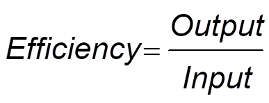
The purpose of space-conditioning and water-heating equipment is to convert energy from one form to another, and to regulate the flow of that energy. Efficiency is a measure of how effectively the energy is converted or regulated. It is expressed as the ratio:
Equation 4-9
The units of measure in which the input and output energy are expressed may be either the same or different, and vary according to the type of equipment. The Energy Standards use several different measures of efficiency.
Combustion Efficiency is defined in the Appliance Efficiency Regulations as follows:
Combustion efficiency of a space heater means a measure of the percentage of heat from the combustion of gas or oil that is transferred to the space being heated or lost as jacket loss, as determined using the applicable test method in Section 1604(e).
Boiler means a space heater that is a self-contained appliance for supplying steam or hot water primarily intended for space-heating. Boiler does not include hot water supply boilers.
Where boilers used for space heating are considered to be a form of space heater.
Thermal efficiency is used as the efficiency measurement for gas and oil boilers with rated input greater than or equal to 300,000 Btu/hr. It is a measure of the percent of energy transfer from the fuel to the heat exchanger (HX). Input and output energy are expressed in the same units so that the result has non-dimensional units:
Equation 4-10
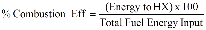
Note: Combustion efficiency does not include losses from the boiler jacket. It is strictly a measure of the energy transferred from the products of combustion.
Fan Power Index is the power consumption of the fan system per unit of air moved per minute (W/cfm) at design conditions.
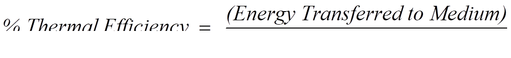
Thermal Efficiency is defined in the Appliance Efficiency Regulations as a measure of the percentage of heat from the combustion of gas, which is transferred to the space or water being heated as measured under test conditions specified. The definitions from the Appliance Efficiency Regulations are:
1. Thermal Efficiency of a space heater means a measure of the percentage of heat from the combustion of gas or oil that is transferred to the space being heated, or in the case of a boiler, to the hot water or steam, as determined using the applicable test methods in Section 1604(e).
2. Thermal Efficiency of a water heater means a measure of the percentage of heat from the combustion of gas or oil that is transferred to the water, as determined using the applicable test method in Section 1604(f).
3. Thermal Efficiency of a pool heater means a measure of the percentage of heat from the input that is transferred to the water, as determined using the applicable test method in Section 1604(g).
Equation 4-11
The concepts of spaces, zones, and space-conditioning systems
are discussed in this subsection.
Fan System is a fan or collection of fans that are used in the scope of the Prescriptive requirement for fan-power limitations §140.4(c). defines fan-systems as all fans in the system that are required to operate at design conditions in order to supply air from the heating or cooling source to the conditioned space, and to return it back to the source or to exhaust it to the outdoors. For cooling systems this includes supply fans, return fans, relief fans, fan coils, series-style fan powered boxes, parallel-style fan powered boxes and exhaust fans. For systems without cooling this includes supply fans, return fans, relief fans, fan coils, series-style fan powered boxes, parallel-style fan powered boxes and exhaust fans. Parallel-style fan-powered boxes are often not included in a terminal unit where there is no need for heating as the fans are only needed for heating.
Space is not formally defined in the Energy Standards, but is considered to be an area that is physically separated from other areas by walls or other barriers. From a mechanical perspective, the barriers act to inhibit the free exchange of air with other spaces. The term “space” may be used interchangeably with “room.”
Space Conditioning Zone, is a space or group of spaces within a building with sufficiently similar comfort conditioning requirements so that comfort conditions, as specified in §140.4(b)3, as applicable, can be maintained throughout the zone by a single controlling device. It is the designer’s responsibility to determine the zoning; in most cases each building exposure will consist of at least one zone. Interior spaces that are not affected by outside weather conditions usually can be treated as a single zone.
A building will generally have more than one zone. For example, a facility having 10 spaces with similar conditioning that are heated and cooled by a single space-conditioning unit using one thermostat is one zone. However, if a second thermostat and control damper, or an additional mechanical system, is added to separately control the temperature within any of the 10 spaces, then the building has two zones.
Space-Conditioning System is used to define the scope of the requirements of the Energy Standards. It is a catch-all term for mechanical equipment and distribution systems that provide either collectively or individually- heating, ventilating, or cooling within or associated with conditioned spaces in a building. HVAC equipment is considered part of a space-conditioning system if it does not exclusively serve a process within the building. Space conditioning systems include general and toilet exhaust systems.
Space-conditioning systems may encompass a single HVAC unit and distribution system (such as a package HVAC unit) or include equipment that services multiple HVAC units (such as a central outdoor air supply system, chilled water plant equipment or central hot water system).
 |topic=Section 4.10.3 – NR-Related Topics
Exhaust Air is air being removed from any space or piece of equipment and conveyed directly to the atmosphere by means of openings or ducts. The exhaust may serve specific areas, such as toilet rooms, or may be for a general building relief, such as an economizer.
Make-up Air is air provided to replace air being exhausted.
Mixed Air is a combination of supply air from multiple air streams. The term mixed air is used in the Energy Standards in an exception to the prescriptive requirement for space conditioning zone controls §140.4(d). In this 'manual the term mixed air is also used to describe a combination of outdoor and return air in the mixing plenum of an air handling unit.
Outdoor Air is air taken from outdoors and not previously circulated in the building. For the purposes of ventilation, outdoor air is used to flush out pollutants produced by the building materials, occupants and processes. To ensure that all spaces are adequately ventilated with outdoor air, the Energy Standards require that each space be adequately ventilated (See Section 4.3).
Return Air is air from the conditioned area that is returned to the conditioning equipment either for reconditioning or exhaust. The air may return to the system through a series of ducts, or through plenums and airshafts.
Supply Air is air being conveyed to a conditioned area through ducts or plenums from a space-conditioning system. Depending on space requirements, the supply may be heated, cooled, or neutral.
Transfer Air is air that is transferred directly from either one space to another or from a return plenum to a space. Transfer air is a way of meeting the ventilation requirements at the space level and is an acceptable method of ventilation per §120.1. It works by transferring air with a low level of pollutants from an over ventilated space) to a space with a higher level of pollutants (See Section 4.3).
Space-conditioning systems can be grouped according to how the airflow is regulated as follows:
Constant Volume System is a space-conditioning system that delivers a fixed amount of air to each space. The volume of air is set during the system commissioning.
Variable Air Volume (VAV) System is a space conditioning system that maintains comfort levels by varying the volume of conditioned air to the zones served. This system delivers conditioned air to one or more zones. There are two styles of VAV systems, single-duct VAV where mechanically cooled air is typically supplied and reheated through a duct mounted coil, and dual-duct VAV systems where heated and cooled streams of air are blended at the zone level. In single-duct VAV systems the duct serving each zone is provided with a motorized damper that is modulated by a signal from the zone thermostat. The thermostat also controls the reheat coil. In dual-duct VAV systems the ducts serving each zone are provided with motorized dampers that blend the supply air based on a signal from the zone thermostat.
Pressure Dependent VAV Box has an air damper whose position is controlled directly by the zone thermostat. The actual airflow at any given damper position is a function of the air static pressure within the duct. Because airflow is not measured, this type of box cannot precisely control the airflow at any given moment: a pressure dependent box will vary in output as other boxes on the system modulate to control their zones.
Pressure Independent VAV Box has an air damper whose position is controlled on the basis of measured airflow. The setpoint of the airflow controller is, in turn, reset by a zone thermostat. A maximum and minimum airflow is set in the controller, and the box modulates between the two according to room temperature.
Return Air Plenum is an plenum is an air compartment or chamber including uninhabited crawl spaces, areas above a ceiling or below a floor, including air spaces below raised floors of computer/data processing centers, or attic spaces, to which one or more ducts are connected and which forms part of either the supply air, return air or exhaust air system, other than the occupied space being conditioned. The return air temperature is usually within a few degrees of space temperature.
When a space-conditioning system supplies air to one or more zones, different zones may be at different temperatures because of varying loads. Temperature regulation is normally accomplished by varying the conditioned air supply (variable volume), by varying the temperature of the air delivered, or by a combination of supply and temperature control. With multiple zone systems, the ventilation requirements or damper control limitations may cause the cold air supply to be higher than the zone load, this air is tempered through reheat or mixing with warmer supply air to satisfy the actual zone load. §140.4(c) limits the amount of energy used to simultaneously heat and cool the same zone as a basis of zone temperature control.
A. Zone Reheat is the heating of air that has been previously cooled by cooling equipment or systems or an economizer. A heating device, usually a hot water coil, is placed in the zone supply duct and is controlled via a zone thermostat. Electric reheat is sometimes used, but is severely restricted by the Energy Standards.
B. Zone Recool is the cooling of air that has been previously heated by space conditioning equipment or systems serving the same building. A chilled water or refrigerant coil is usually placed in the zone supply duct and is controlled via a zone thermostat. Re-cooling is less common than reheating.
C. Zone Air Mixing occurs when more than one stream of conditioned air is combined to serve a zone. This can occur at the HVAC system (e.g. multizone), in the ductwork (e.g. dual-duct system) or at the zone level (such as a zone served by a central cooling system and baseboard heating). In some multizone and dual duct systems an unconditioned supply is used to temper either the heating or cooling air through mixing. §140.4(c) only applies to systems that mix heated and cooled air.
4.10.7.1 Air Economizers
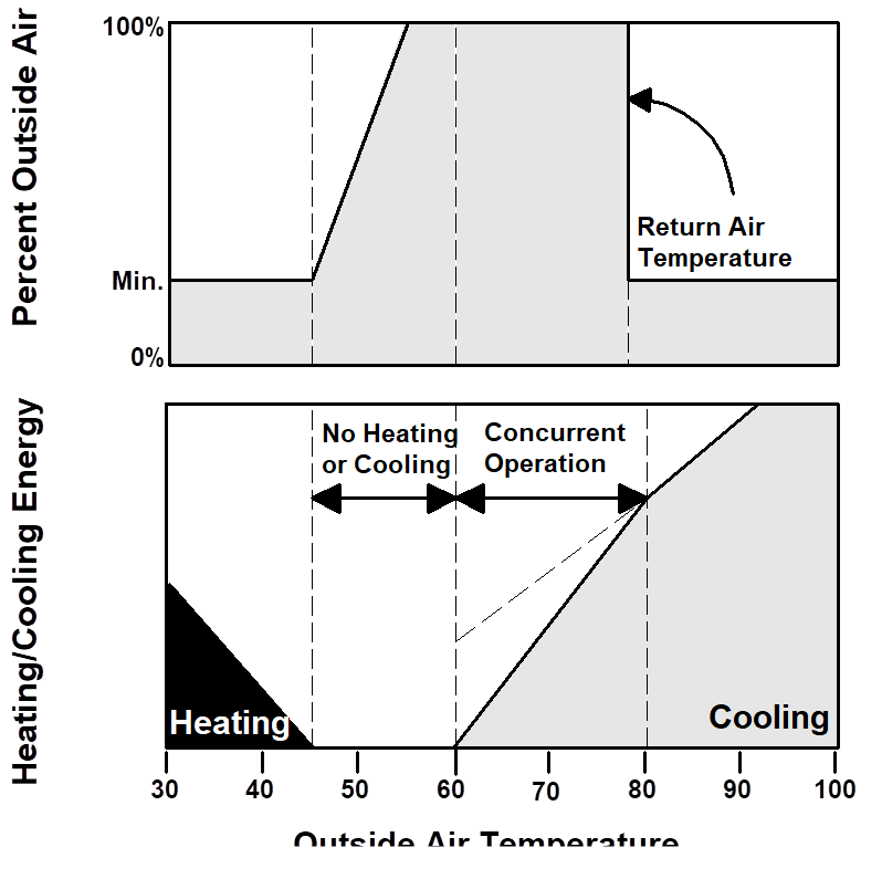
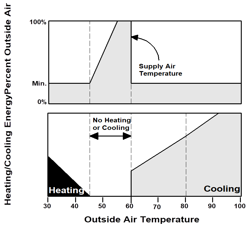
When the compliance path chosen for meeting the Energy Standards requires an economizer, the economizer must be integrated into the system so that it is capable of satisfying part of the cooling load while the rest of the load is satisfied by the refrigeration equipment. The Energy Standards also require that all new economizers meet the Acceptance Requirements for Code Compliance before a final occupancy permit may be granted. The operation of an integrated air economizer is diagrammed in Figure 4-32.
When outdoor air is sufficiently cold, the economizer satisfies all cooling demands on its own. As the outdoor temperature (or enthalpy) rises, or as system cooling load increases, a point may be reached where the economizer is no longer able to satisfy the entire cooling load. At this point the economizer is supplemented by mechanical refrigeration, and both operate concurrently. Once the outside drybulb temperature (for temperature controlled economizer) or enthalpy (for enthalpy economizers) exceeds that of the return air or a predetermined high limit, the outside air intake is reduced to the minimum required, and cooling is satisfied by mechanical refrigeration only.
Nonintegrated economizers cannot be used to meet the economizer requirements of the prescriptive compliance approach. In nonintegrated economizer systems, the economizer may be interlocked with the refrigeration system to prevent both from operating simultaneously. The operation of a nonintegrated air economizer is diagrammed in Figure 4-33. Nonintegrated economizers can only be used if they comply through the performance approach.
4.10.7.2 Water Economizers
A water economizer is a system by which the supply air of a cooling system is cooled directly or indirectly by evaporation of water, or other appropriate fluid, in order to reduce or eliminate the need for mechanical cooling.
As with an air economizer, a water economizer must be integrated into the system so that the economizer can supply a portion of the cooling concurrently with the refrigeration system.
There are three common types of water-side economizers:
1. Strainer-cycle or chiller-bypass water economizer. This system, depicted in Figure 4-34 below, does not meet the prescriptive requirement as it cannot operate in parallel with the chiller. This system is applied to equipment with chilled water coils.
2. Water-precooling economizer. This system depicted in Figure 4-34 and Figure 4-36 below meets the prescriptive requirement if properly sized. This system is applied to equipment with chilled water coils.
3. Air-precooling water economizer. This system depicted in Figure 4-37 below also meets the prescriptive requirement if properly sized. The air-precooling water economizer is appropriate for water-source heat pumps and other water-cooled HVAC units.
To comply with the prescriptive requirements, the cooling tower serving a water-side economizer must be sized for 100 percent of the anticipated cooling load at the off-design outdoor-air condition of 50°F dry bulb/45°F wet bulb. This requires rerunning the cooling loads at this revised design condition and checking the selected tower to ensure that it has adequate capacity.

This system does not meet the prescriptive requirement as it cannot operate in parallel with the chiller


§120.1 address ventilation requirements for buildings and uses the term of “unusual sources of contamination.” In this context, such contaminants are considered to be chemicals, materials, processes or equipment that produce pollutants which are considered harmful to humans, and are not typically found in most building spaces. Examples may include some cleaning products, blueprint machines, heavy concentrations of cigarette smoke and chemicals used in various processes.
The designation of such spaces is left to the designer’s discretion, and may include considerations of toxicity, concentration and duration of exposure. For example, while photocopiers and laser printers are known to emit ozone, scattered throughout a large space it may not be of concern. A heavy concentration of such machines in a small space may merit special treatment (See Section 4.3).
Demand controlled ventilation is required for use on systems that have an outdoor air economizer, and serve a space with a design occupant density, or maximum occupant load factor for egress purposes in the CBC, greater than or equal to 25 people per 1000 ft² (40 ft2/ person) §120.1(c)3. Demand controlled ventilation is also allowed as an exception in the ventilation requirements for intermittently occupied systems §120.1(c)1, §120.1(c)3 and §120.1(c)4. It is a concept in which the amount of outdoor air used to purge one or more offending pollutants from a building is a function of the measured level of the pollutant(s).
§120.1 allows for demand controlled ventilation devices that employ a carbon dioxide (CO2) sensor. Carbon dioxide sensors measure the level of carbon dioxide, which is used as a proxy for the amount of pollutant dilution in densely occupied spaces. CO2 sensors have been on the market for many years and are available with integrated self-calibration devices that maintain a maximum guaranteed signal drift over a 5-year period. ASHRAE Standard 62 provides some guidelines on the application of demand controlled ventilation.
Demand controlled ventilation is available at either the system level (used to reset the minimum position on the outside air damper) and at the zone level (used to reset the minimum airflow to the zone). The zone level devices are sometimes integrated into the zone thermostat.
Occupant sensor ventilation control devises are required in multipurpose rooms less than 1000 ft2, classrooms greater than 750 ft2 and conference, convention, auditorium, and meeting center rooms greater than 750 ft2 that do not generate dust, fumes, vapors, or gasses §120.1(c)5 and §120.2(e)3. Occupant sensor control devises are used to setup the operating cooling temperature, setback the operating heating temperature, and set minimum ventilation rate levels during unoccupied periods. Spaces with an area of less than 1,500 ft2 are exempt from the demand control ventilation requirements specified in §120.1(c)3 if employing occupant sensor ventilation control devices in accordance with §120.1(c)5
The demand controlled ventilation devices discussed here are allowed and/or required only in spaces that are intermittently occupied. An intermittently occupied space is considered to be an area that is infrequently or irregularly occupied by people. Examples include auction rooms, movie theaters, auditoriums, gaming rooms, bars, restaurants, conference rooms and other assembly areas. Because the Energy Standards requires base ventilation requirement in office spaces that are very close to the actual required ventilation rate at 15 cfm per person, these controls may not save significant amounts of energy for these low-density applications. However, even in office applications, some building owners may install CO2 sensors as a way to monitor ventilation conditions and alert to possible malfunctions in building air delivery systems.