
The water heating distribution system is the configuration of piping (and pumps and controls in the case of recirculating systems) that delivers hot water from the water heater to the end-use points within the building. For systems designed for single-family buildings or individual dwelling units in a multifamily building, the system will resemble one of the system types described below under dwelling unit distribution systems. In multifamily buildings, the use of a central water heater and central recirculation distribution system that brings hot water close to all the dwelling units is also common. A description of the recognized systems for serving single and multiple dwelling units are listed in the following two sections. The installation of a hot water distribution system that does not meet all of the installation guidelines discussed in this compliance manual and in the Reference Appendix RA3 and RA4 must have either the deficiencies corrected or compliance calculations using the performance approach assuming that the installed distribution system is substandard. In all cases, the locations of the water heaters and fixtures should be given consideration at the beginning of building design. By minimizing the length of distribution piping, energy use, water waste, wait time for hot water and construction cost can all be reduced.
5.6.2.1 Standard Distribution System (Trunk-and-Branch and Mini-manifold Configurations)
The most basic plumbing layout, and assumed as the reference design in the performance approach, is represented by the conventional trunk-and-branch layout. This layout of a trunk-and-branch system may include one or more trunks each serving a portion of the building. The trunks are subdivided by branches that serve specific rooms, and these are in turn divided into twigs that serve a particular point of use. This distribution system class includes mini-manifold layouts (see Figure 5-8), which incorporate trunk lines that feed remote manifolds that then distribute water via twigs to the end-use points. A standard distribution system may not incorporate a pump for hot water recirculation. Piping cannot be run up to the attic and then down to points of use on the first floor.
Installation Criteria and Guidelines
No pumps may be used to recirculate hot water with the standard distribution system. All applicable mandatory features must be met. When designing a trunk-and-branch system, the concern is keeping all segments of the system as short and as small a diameter as possible. Even an insulated pipe will lose most of the stored heat within 30 minutes. The other issue to consider is that if hot water gets into a cold water line, all the water in the pipe must be discharged, and up to an additional third of the volume of hot water will be needed to heat the pipe so that the water arriving at the point of use will be the desirable temperature. The requirements and guidelines for the installation of the standard distribution system are included in Reference Appendix RA3 and RA4 - Eligibility Criteria for Energy Efficiency Measures.
5.6.2.2 Central Parallel Piping System
The primary design concept in a central parallel piping system is an insulated main trunk line that runs from the water heater to one or more manifolds, which then feeds use points with ½” or smaller plastic piping. The traditional central system with a single manifold (Figure 5-9) must have a maximum pipe run length of 15 feet between the water heater and the manifold. With the advent of mini-manifolds, the central parallel piping system can now accommodate multiple mini-manifolds in lieu of the single central manifold, provided that a) the sum of the piping length from the water heater to all the mini-manifolds is less than 15 feet and b) all piping downstream of the mini-manifolds is nominally ½ inch or smaller.

Installation Criteria and Guidelines
All applicable mandatory measures must be met. Piping from the manifold cannot be run up to the attic and then down to points of use on the first floor. The intent of a good parallel piping design is to minimize the volume of water entrained in piping between the water heater and the end-use points, with a focus on reducing the length of the 3/-inch or 1-inch line from the water heater to the manifold(s). To encourage reducing the pipe length between the water heater and manifold, there is a distribution system compliance credit for installations that are HERS-verified to have no more than 5 feet of piping between the water heater and the manifold(s). The manifold feeds hot water use points with 3/8 or 1/2 inch PEX tubing. (Check with enforcement agencies on the use of 3/8-inch piping in the event that it is prohibited without engineering approval.) The adopted requirements for installation guidelines are included in RA3 and RA4.
5.6.2.3 Point of Use
A point-of-use distribution system design significantly reduces the volume of water between the water heater and the hot water use points. Use of this type of system requires a combination of good architectural design (that is, water heater location adjacent to hot water use points), an indoor mechanical closet, or the use of multiple water heaters. Figure 5-10 provides an example of the latter approach where three water heaters are installed close to the use points. For compliance with this credit, field verification is required. This system is not applicable to systems serving multiple dwelling units.
Installation Criteria and Guidelines
All applicable mandatory features must be met, and the distance between the water heater and any fixture using hot water cannot exceed the length specified in Table 5-9 below. The adopted requirements for installation guidelines are included in RA3 and RA4. All water heaters and hot water fixtures must be shown on plans submitted for a local building department plan check.

|
Size Nominal, Inch |
Length of Pipe (feet) |
|
3/8” |
15 |
|
1/2” |
10 |
|
3/4” |
5 |
5.6.2.4 HERS-Verified Compact Design
A compact distribution system design means that all the hot water use points in a non-recirculating distribution system are within a specified length of piping to the water heater that serves those fixtures.
If the user is complying with the Energy Standards using the prescriptive approach, there is the option of using compact hot water distribution design in combination with a propane or natural gas storage water heater (and Quality Insulation Installation, if installing a gas storage water heater that is 55 gallons or less). Compact hot water distribution design can also be used to help achieve the required energy budget (in other words, as a compliance credit) if the user is complying with the Energy Standards using the performance approach. To use the compact hot water distribution design to comply with Energy Standards, the design and installation must be HERS-verified and meet the Reference Appendix RA4.4.16 requirements.
Table 5-10 below specifies the maximum pipe run length that meets the compact design criteria based on floor area served (floor area served = building conditioned floor area divided by the number of water heaters), which recognizes that multiple water heaters may be beneficial in achieving a more compact distribution system.
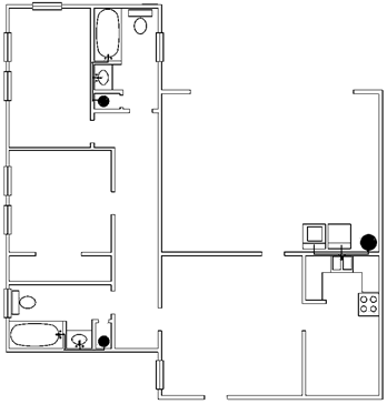
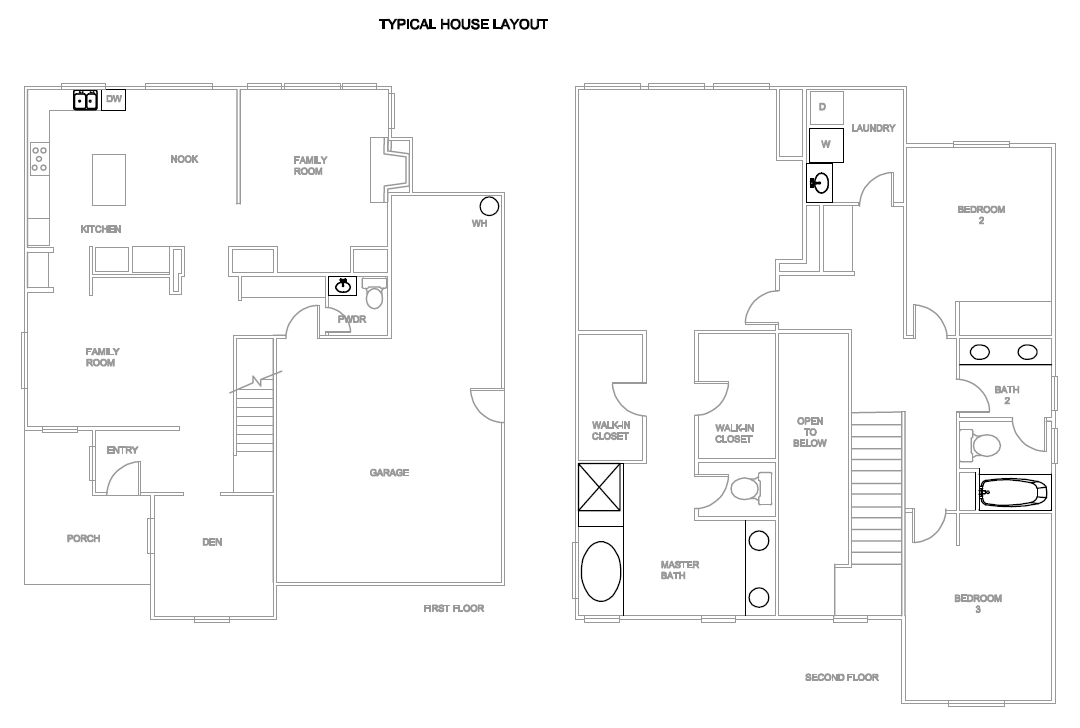
Typical hot water distribution systems are often designed to be much larger than needed in terms of pipe length. A design consideration that often is overlooked is the location of the water heater relative to hot water use points. Figure 5-11 below shows a common production home layout with the water heater located in the corner of the garage and hot water use points in each corner of the house.
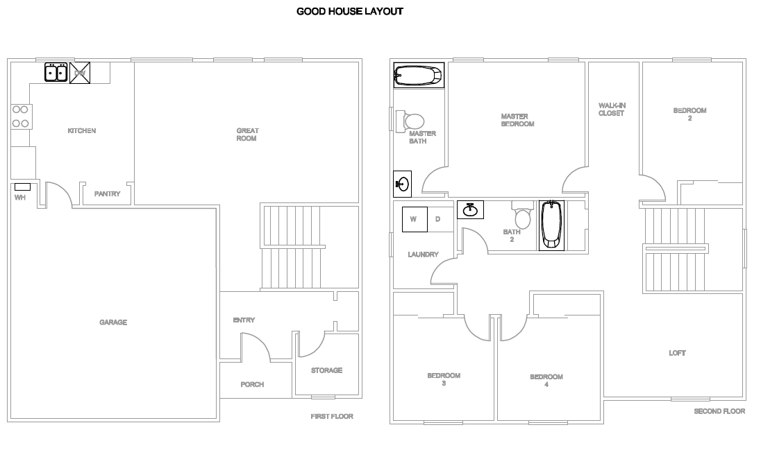
A more effective hot water distribution system design is shown in Figure 5-12. In the figure, the location of the water heater is near the kitchen and bathrooms and laundry area. The location of hot water use points plays an integral role in achieving the benefits associated with a compact distribution system design.


|
Floor Area Served (ft2) |
Maximum Water Heater To Use Point Distance (ft) |
|
< 1000 |
28’ |
|
1001 – 1600 |
43’ |
|
1601 – 2200 |
53’ |
|
2201 – 2800 |
62’ |
|
>2800 |
68’ |
5.6.2.5 Pipe Insulation Credit
Compliance credit is available in the performance compliance approach if all piping in the hot water distribution system is insulated from the water heater to each fixture or appliance. In addition to the mandatory pipe insulation requirements described in Section 5.3.5.1, pipe insulation should be checked to ensure all elbows and tees are fully insulated and fit tightly to the pipe. No piping should be visible due to insulation voids with the exception of the last segment of pipe that penetrates walls and connects to the fixture or appliance. Additional credit is available if the insulation is verified by a HERS inspection.
5.6.2.6 Recirculation System – Non-Demand Control Options
This type of distribution system encompasses all recirculation strategies that do not incorporate a demand control to minimize recirculating pump operation. Under this category, recirculation system types include uncontrolled continuous recirculation, timer control, temperature control, and time/temperature controls. The intent is to clearly distinguish between recirculation system control options that result in very little daily pump operating time (demand control strategies) and the other strategies where pump runs continuously or run time is much more uncertain. Recirculation systems are known to save water, but the energy impact can be very high in a poorly designed and/or controlled system.
Installation Criteria
All piping used to recirculate hot water must be insulated to meet the mandatory requirements. Since the standards require pipe insulation for recirculating systems, these systems are not eligible for the pipe insulation credit. For systems serving a single dwelling unit, the recirculating loop within a dwelling unit must be laid out to be within 8 feet of all hot water fixtures served by the recirculating loop. As with all recirculation systems, an intelligent loop layout (loop in-board of hot water use points) and proper insulation installation are essential in obtaining desired performance. Piping in a recirculation system cannot be run up to the attic and then down to points of use on the first floor. The adopted requirements for installation guidelines are included in Reference Appendices RA3 and RA4.
5.6.2.7 Recirculation System – Demand Control
A demand-control recirculation system uses brief pump operation in response to a hot water demand “signal” to circulate hot water through the recirculation loop. The system must have a temperature sensor, typically located at the most remote point of the recirculation loop. Some water heaters have temperature sensors located within the water heater. The sensor provides input to the controller to terminate pump operation when the sensed temperature rises. Typical control options include manual push button controls or occupancy sensor controls installed at key use areas (bathrooms and/or kitchen). Push button control is preferred from a performance perspective, since it eliminates “false signals” for pump operation that an occupancy sensor could generate. The adopted requirements for installation guidelines are included in Reference Appendices RA3 and RA4.
Installation Criteria
All criteria listed for continuous recirculation systems apply. Piping in a recirculation system cannot be run up to the attic and then down to points of use on the first floor.
Pump start-up must be provided by a push button, flow switch, or occupancy sensor. Pump shut-off must be provided by a combination of a temperature sensing device that shuts off the pump when the temperature sensor detects no more than 10 degree rise above the initial temperature of water in the pipe or when the temperature reaches 102 degree F. Moreover, the controls shall limit the maximum pump run time to five minutes or less.
For a system serving a single dwelling, push buttons and sensors must be installed in all locations with a sink, shower, or tub, with the exception of the laundry room.
Plans must include a wiring/circuit diagram for the pump and timer/temperature sensing device and specify whether the control system is manual (push button or flow switch) or other control means, such as an occupancy sensor.
5.6.3.1 Multiple Dwelling Units: Central Demand Recirculation System (Standard Distribution System)
The standard distribution system for water heaters serving multiple dwelling units incorporates recirculation loops, which bring hot water to different parts of the building, and a demand control, which automatically shuts off the recirculation pump when the recirculation flow is not needed. In summary, central recirculation systems include three components, recirculation loops, branch pipes, and pipes within dwelling units. Recirculation loops are used to bring hot water close to all dwelling units but are not expected to go through each dwelling unit. Branch pipes are used to connect pipes within dwelling units and the recirculation loops. This concept is illustrated in Figure 5-13. Designs of distribution systems within dwelling units are similar to those serving single dwelling units, described in Section 5.6.2.
. 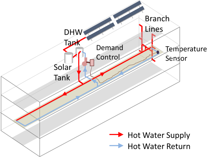
Demand controls for central recirculation systems are automatic control systems that control the recirculation pump operation based on measurement of hot water demand and hot water return temperatures.
5.6.3.2 Multiple Dwelling Units: Recirculation Temperature Modulation Control
A recirculation temperature modulation control shall reduce the hot water supply temperature when hot water demand is determined to be low by the control system. The control system may use a fixed control schedule or dynamic control schedules based measurements of hot water demand. The daily hot water supply temperature reduction, which is defined as the sum of temperature reduction by the control in each hour within a 24-hour period, shall be more than 50 degrees Fahrenheit to qualify for the energy savings credit. Qualifying equipment shall be listed with the Commission.
Recirculation systems shall also meet the requirements of §110.3.
5.6.3.3 Multiple Dwelling Units: Recirculation Continuous Monitoring Systems
Systems that qualify as a recirculation continuous monitoring systems for domestic hot water systems serving multiple dwelling units shall record no less frequently than hourly measurements of key system operation parameters, including hot water supply temperatures, hot water return temperatures, and status of gas valve relays for water-heating equipment. The continuous monitoring system shall automatically alert building operators of abnormalities identified from monitoring results. Qualifying equipment or services shall be listed with the Commission.
Recirculation systems shall also meet the requirements of §110.3.
5.6.3.4 Non-recirculating Water Heater System
Multiunit buildings may also use systems without a recirculation system, if the served dwelling units are closely located so that the branch pipes between the water-heating equipment and dwelling units are relatively short. Long branch lines will lead to excessive energy and water waste.