This group of building descriptors relate to the secondary HVAC systems. There is not a one-to-one relationship between secondary HVAC system components in the proposed design and the baseline building since the baseline building system is determined from building type, size, and number of floors. Where the standard design for a building descriptor varies with the standard design HVAC system selection, the baseline is specified as a table with the applicable value for each of the 11 baseline systems.
The HVAC standard design (baseline) systems are described in the summary tables below for reference. The details of individual building descriptor definitions can be found in section 5.7.1 and in subsections under 5.7.
|
System Description: |
Packaged Terminal Air Conditioner (#1) |
|
Supply Fan Power: |
N/A (fan power integral to unit efficiency), ventilation provided naturally through operable windows |
|
Supply Fan Control: |
Constant volume |
|
Min Supply Temp: |
50 < T < 60 DEFAULT: 20°F below return air temperature |
|
Cooling System: |
Direct expansion (DX) |
|
Cooling Efficiency: |
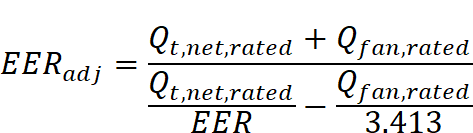
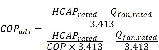
Minimum seasonal energy efficiency ratio (SEER) or energy efficiency ratio (EER) based on equipment type and output capacity of standard design unit(s). Adjusted EER is calculated to account for supply fan energy. |
|
Maximum Supply Temp: |
85 < T < 110 DEFAULT: 100 |
|
Heating System: |
Gas furnace (#3) or heat pump (#4) |
|
Heating Efficiency: |
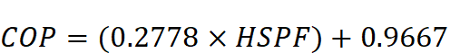
Minimum annual fuel utilization efficiency (AFUE), thermal efficiency, coeffience of performance (COP) or heating season performance factor (HSPF) based on equipment type and output capacity of standard design unit(s). |
|
Economizer: |
None |
|
Ducts: |
N/A (unducted) |
|
System Description: |
Four-Pipe Fan Coil (#2) |
|
Supply Fan Power: |
0.35 W/cfm |
|
Supply Fan Control: |
Cycles with load |
|
Min Supply Temp: |
50 < T < 60 DEFAULT: 20°F below return air temperature |
|
Space Temp Control: |
SAT is fixed at 55°F. Fan cycles to meet the load. |
|
Cooling System: |
Chilled water |
|
Cooling Efficiency: |
Minimum kW/ton and IPLV per Path B chiller requirements in Title 24 Section110.2 |
|
Maximum Supply Temp: |
85 < T < 110 DEFAULT: 100 |
|
Heating System: |
Boiler |
|
Heating Efficiency: |
Minimum AFUE, thermal efficiency per Section 110.2 of Title 24 Part 6 for the applicable heating capacity |
|
Economizer: |
None |
|
Ducts: |
N/A (unducted) |
|
System Description: |
Packaged Single Zone with Gas Furnace/Electric Air Conditioning (#3) |
|
Supply Fan Power: |
See Section 5.7.3 |
|
Supply Fan Control: |
Constant volume |
|
Min Supply Temp: |
50 < T < 60 DEFAULT: 20°F below return air temperature |
|
Cooling System: |
Direct expansion (DX) |
|
Cooling Efficiency: |
Minimum SEER or EER based on equipment type and output capacity of standard design unit(s). Adjusted EER is calculated to account for supply fan energy. |
|
Maximum Supply Temp: |
85 < T < 110 DEFAULT: 100 |
|
Heating System: |
Gas furnace (#3) |
|
Heating Efficiency: |
Minimum AFUE, Thermal Efficiency, COP or HSPF based on equipment type and output capacity of standard design unit(s) |
|
Economizer: |
Integrated economizer with differential dry-bulb high limit, when mechanical cooling output capacity of the standard design as modeled in the compliance run by the compliance software is over 54,000 Btu/hr |
|
Ducts: |
For ducts installed in unconditioned buffer spaces or outdoors as specified in §140.4(l), the duct system efficiency shall be as modified by accounting for duct leakage rate |
|
System Description: |
Packaged VAV with Boiler and Reheat |
|
Supply Fan Power: |
See Section 5.7.3 |
|
Supply Fan Control: |
VAV - variable speed drive |
|
Relief Fan Control: |
See fan section |
|
Minimum Supply Temp: |
50 < T < 60 DEFAULT: 20°F below return air temperature |
|
Cooling System: |
Direct expansion (DX) |
|
Cooling Efficiency: |
Minimum efficiency based on average standard design output capacity of equipment unit(s) |
|
Maximum Supply Temp: |
90 < T < 110 DEFAULT: 105 |
|
Heating System: |
Gas boiler |
|
Hot Water Pumping System |
Variable flow (two-way valves) riding the pump curve |
|
Heating Efficiency: |
Minimum efficiency based on average standard design output capacity of equipment unit(s) |
|
Economizer: |
Integrated dry bulb economizer with differential dry-bulb limit |
|
System Description: |
Chilled Water VAV with Reheat |
|
Supply Fan Power: |
See Section 5.7.3 |
|
Supply Fan Control: |
VAV - variable speed drive |
|
Return Fan Control: |
Same as supply fan |
|
Minimum Supply Temp: |
50 < T < 60 DEFAULT: 20°F below return air temperature |
|
Cooling System: |
Chilled water |
|
Chilled Water Pumping System |
Variable flow (two-way valves) with a variable speed drive (VSD) on the pump if three or more fan coils or air handlers; constant volume flow with water temperature reset control if less than three fan coils or air handlers; reset supply pressure by demand if standard system has DDC controls |
|
Cooling Efficiency: |
Minimum efficiency based on standard design output capacity of equipment unit(s) |
|
Maximum Supply Temp: |
90 < T < 110 DEFAULT: 105 |
|
Heating System: |
Gas boiler |
|
Hot Water Pumping System |
Variable flow (two-way valves) riding the pump curve if three or more fan coils or air handlers; constant volume flow with water temperature reset control if less than three fan coils or air handlers; reset supply pressure by demand |
|
Heating Efficiency: |
Minimum efficiency based on standard design output capacity of equipment unit(s) |
|
Economizer: |
Integrated dry bulb economizer with differential dry-bulb limit |
|
System Description: |
Single-Zone VAV System |
|
Supply Fan Power: |
See Section 5.7.3 |
|
Supply Fan Control |
Variable-speed drive |
|
Minimum Supply Temp: |
50 < T < 60 DEFAULT: 20°F below return air temperature |
|
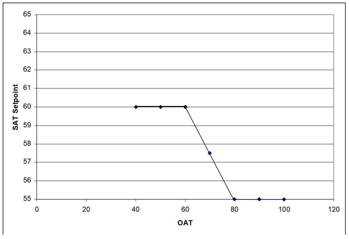
Supply Temp Control: |
Supply air temperature setpoint shall be linearly reset from minimum at 50 percent cooling load and above to maximum at 0 percent cooling load. Fan volume shall be linearly reset from 100 percent air flow at 100 percent cooling load to minimum air flow at 50 percent cooling load and below. Minimum fan volume setpoint shall be 50 percent. (This is effectively an “airflow first” sequence.) |
|
Cooling System: |
Direct expansion |
|
Cooling Efficiency: |
Minimum efficiency based on the standard output capacity of specific equipment unit(s) |
|
Compressor Stages: |
Two to four (See minimum unloading ratio requirement) |
|
Maximum Supply Temp: |
90 < T < 110 DEFAULT: 100 |
|
Heating System: |
Gas furnace |
|
Hot Water Pumping System |
Variable flow (two-way valves) riding the pump curve if three or more fan coils; constant volume flow with water temperature reset control if less than three fan coils; reset supply pressure by demand if standard system has DDC controls |
|
Heating Efficiency: |
Minimum efficiency based on the standard output capacity of specific equipment unit(s) |
|
Economizer: |
Integrated dry bulb economizer with differential dry-bulb high limit |
|
System Description: |
Heating and ventilation only system |
|
Supply Fan Power: |
See fan power details |
|
Supply Fan Control |
Constant volume |
|
Minimum Supply Temp: |
N/A |
|
Cooling System: |
None |
|
Cooling Efficiency: |
N/A |
|
Maximum Supply Temp: |
90 < T < 110 DEFAULT: 100 |
|
Heating System: |
Gas furnace |
|
Hot Water Pumping System |
N/A |
|
Heating Efficiency: |
Minimum efficiency based on the standard output capacity of specific equipment unit(s) |
|
Economizer: |
TBD |
|
System Description: |
Computer Room Air Handler (CRAH) |
|
Supply Fan Power: |
0.49 W/cfm at design air flow where economizer is required, 0.39 W/cfm where economized is not required; |
|
Supply Fan Control |
variable speed drive; fan power part-load curve is for “VSD with static pressure reset” |
|
Minimum Supply Temp: |
60 F |
|
Cooling System: |
Single zone VAV with chilled water cooling source |
|
Cooling Efficiency: |
Same as System #6 (Built-up VAV) |
|
Maximum Supply Temp: |
80°F |
|
Heating System: |
None |
|
Economizer: |
Integrated 100 percent outside air economizer with differential dry-bulb limit |
|
Supply Temp Control: |
VAV: Supply air temperature setpoint shall be reset between 60 °F and 80°F; fan volume shall be reset between 100 percent and 50 percent flow, depending on cooling load; minimum fan volume setpoint shall be 50 percent |
|
System Description: |
Computer Room Air Conditioner (CRAC) |
|
Supply Fan Power: |
0.49 W/cfm at design flow (see equipment sizing) where economizer is required; 0.39 W/cfm whereeconomizer is not required |
|
Supply Fan Control |
Constant speed if the computer room receptacle load is less than 17.5 kW; otherwise, variable speed drive. Fan power curve for VSD is ‘VSD with static pressure reset‘. |
|
Relief Fan Control: |
No relief fan |
|
Minimum Supply Temp: |
60°F |
|
Cooling System: |
Single zone Air-cooled DX |
|
Cooling Capacity: |
Equipment design CFM and cooling capacity sized at 115 percent of the capacities generated from a system sizing run; one system per zone |
|
Cooling Efficiency: |
Appliance Standards Table C-9 |
|
Maximum Supply Temp: |
80°F |
|
Heating System: |
None |
|
Economizer: |
Integrated 100 percent outside air economizer with differential dry-bulb limit if the net cooling capacity is greater than 54,000 Btu/h |
|
Supply Temp Control: |
VAV: Supply air temperature setpoint shall be between
60 F and 80 F; fan supply air volume shall be reset between 100 percent
and 50 percent of the rated fan condition, depending on the cooling load;
minimum fan volume setpoint shall be 50 percent |
|
System Description: |
Laboratory HVAC System |
|
Supply Fan Power: |
See supply fan static pressure, supply fan efficiency, and supply fan motor efficiency for standard design specifications |
|
Supply Fan Control |
Variable-speed drive |
|
Return Fan Control: |
No return fans |
|
Exhaust Fan Control: |
Variable volume, variable-speed drive if total building laboratory exhaust air flow rate is greater than 2,000 cfm and 10 ACH or greater; constant volume otherwise. |
|
Ventilation: |
Same as proposed but subject to a minimum 6 ACH; system is 100 percent outside air |
|
Minimum Supply Temp: |
55°F |
|
Cooling System: |
PVAV with air-cooled DX if total lab floor area <150,000 ft2; water-cooled chiller if greater than 150,000 ft2 floor area |
|
Cooling Capacity: |
Equipment fan CFM and cooling capacity sized at 115 percent of the capacities determined using a sizing run; one laboratory system per floor when total building laboratory floor area is 10,000 ft2 or greater, otherwise one laboratory system per zone |
|
Cooling Efficiency: |
Minimum efficiency requirements per Section 110.2 |
|
Maximum Supply Temp: |
95 |
|
Heating System: |
Gas furnace if building total floor area is 10,000 ft2 or less; hot water coils/boiler if greater than 10,000 ft2 |
|
Economizer: |
integrated 100 percent outside air economizer with differential dry-bulb limit |
|
Supply Temp Control: |
VAV: Supply air temperature setpoint shall be reset upwards by 5 F based on warmest zone; fan volume shall be reset between100 percent and 50 percent flow, depending on cooling load; minimum fan volume setpoint shall be 50 percent CV: supply air temperature setpoint modulates to meet the load |
|
System Description: |
Kitchen HVAC system |
|
Supply Fan Power: |
Fixed supply fan static pressure, see Section 5.7.3 |
|
Supply Fan Control |
Constant speed if total exhaust airflow rate is greater than or equal to 2,000 cfm; otherwise, variable speed drive; fan power ratio at part load is determined by the part load ratio and the static pressure reset system curve |
|
Return Fan Control: |
No return fans |
|
Exhaust Fan Control: |
Variable volume, variable-speed drive if total exhaust air flow rate > 5,000 cfm; constant volume otherwise |
|
Minimum Supply Temp: |
20°F below space temperature setpoint |
|
Cooling System: |
PVAV with air-cooled DX if floor area < 50,000 ft2; water-cooled chiller if greater 50,000 ft2 floor area |
|
Cooling Capacity: |
Cooling capacity sized at 115 percent of the calculated room load; fan airflow sizing based on exhaust airflow requirements; one fan system per room |
|
Cooling Efficiency: |
Minimum efficiency requirements per Section 110.2 |
|
Maximum Supply Temp: |
95°F |
|
Heating System: |
Gas furnace if building total floor area is 10,000 ft2 or less; hot water coils/boiler if greater than 10,000 ft2 |
|
Economizer: |
None |
|
Supply Temp Control: |
VAV: Supply air temperature setpoint shall be linearly reset from minimum at 50 percent cooling load and above to maximum at 0 percent cooling load; fan volume shall be linearly reset from 100 percent air flow at 100 percent cooling load to minimum air flow at 50 percent cooling load and below; minimum fan volume setpoint shall be 50 percent (effectively an “airflow first” sequence) CV: supply air temperature modulates to meet the load |
|
HVAC System Name | |
|
Applicability |
All system types |
|
Definition |
A unique descriptor for each HVAC system |
|
Units |
Text, unique |
|
Input Restrictions |
When applicable, input should match the tags that are used on the plans |
|
Standard Design |
None |
|
Standard Design: Existing Buildings |
|
|
Applicability |
All system types |
|
Definition |
A unique descriptor which identifies the following attributes of an HVAC system: •Number of air decks (one to three) •Constant or variable air flow •Type of terminal device •Fan configuration for multiple deck systems |
|
Units |
List from the choices below |
|
Input Restrictions |
PTAC – Packaged Terminal Air Conditioner PTHP – Packaged Terminal Heat Pump PSZ-AC – Packaged Single Zone PSZ-HP – Packaged Single Zone Heat Pump PVAV – Packaged VAV with Reheat VAV* – VAV with Reheat PSZVAV* – Single Zone VAV PSZVAVHP – Single Zone VAV Heat Pump HV – Heating and Ventilation Only CRAC – Computer Room Air Conditioner CRAH – Computer Room Air Handler FPFC – Four-pipe fan coil DFDD – Dual-fan dual duct RADFLR – Radiant floor heating and cooling WSHP – water-source heat pump SPVAC – Single package vertical air conditioner (minimum efficiency defined in Section 110.2) SPVHP – Single package vertical heat pump (minimum efficiency defined in Section 110.2) * Choice includes series and parallel fan-powered boxes as zone terminal units |
|
Standard Design |
Based on the prescribed system type in the HVAC system map (see Section 5.1.2 Table 4); baseline system types are shown in Table 27 |
|
Standard Design: Existing Buildings |
|
|
Baseline Building System Type |
|
System 1 – PTAC |
|
System 2 – FPFC |
|
System 3 – PSZ-AC |
|
System 5 – Packaged VAV with Reheat |
|
System 6 – VAV with Reheat |
|
System 7 – PSZ-SZVAV |
|
System 9 – Heating and Ventilation |
|
System 10 – CRAC Unit |
|
System 11 – CRAH Unit |
|
System 12 – LAB |
|
System 13 – Kitchen |
|
Air Distribution Type | |
|
Applicability |
All system types |
|
Definition |
Type of air distribution system that is coupled with the HVAC system. The choices are (overhead) mixing ventilation system, underfloor air distribution system (UFAD), and displacement ventilation system (DV). |
|
Units |
List mixing, UFAD, DV |
|
Input Restrictions |
As designed |
|
Standard Design |
Mixing |
|
Standard Design: Existing Buildings |
|
|
Thermal zone List | |
|
Applicability |
All system types |
|
Definition |
Comprehensive list of all thermal zones served by a given HVAC system |
|
Units |
None |
|
Input Restrictions |
As designed |
|
Standard Design |
Same as the proposed design |
|
Standard Design: Existing Buildings |
|
|
Total Cooling Capacity | |
|
Applicability |
All system types |
|
Definition |
The installed cooling capacity of the project. This includes all: •Chillers •Built-up DX •Packaged cooling units |
|
Units |
Cooling tons (12,000 Btu/h per ton) |
|
Input Restrictions |
As designed |
|
Standard Design |
Autosize The cooling capacity shall be oversized by 15 percent. If the number of unmet load hours exceeds 150, increase the cooling capacity according to the procedures in Chapter 2 |
|
Standard Design: Existing Buildings |
|
5.7.2.1 Control System Type
|
Control System Type | |
|
Applicability |
All HVAC systems that serve more than one control zone, as well as the hydronic systems that serve building HVAC systems |
|
Definition |
The type of control system for multi-zone HVAC systems and their related equipment. This input affects the proposed design system specification for zone level controls, supply air temperature reset controls, ventilation controls and fan and pump static pressure part-load curves. See the following building descriptors: •Ventilation control method •Terminal heating control type •Pump part-load curve •Fan part-load curve •Optimal start |
|
Units |
None |
|
Input Restrictions |
List one of the following inputs: Direct digital control (DDC) control to the zone level – DDC systems with control to the zone level Other – other control systems, including pneumatic and DDC systems without control to the zone level |
|
Standard Design |
DDC control to the zone level |
|
Standard Design: Existing Buildings |
|
5.7.2.2 Schedules
|
Cooling Schedule | |
|
Applicability |
All cooling systems |
|
Definition |
A schedule that represents the availability of cooling |
|
Units |
Data structure: schedule, on/off |
|
Input Restrictions |
Schedule group is prescribed in Appendix 5.4A and schedule values are prescribed in Appendix 5.4B. See Section 2.3.3 on how software shall assign schedules when the spaces served by the system are assigned to different schedule groups in Appendix 5.4A. |
|
Standard Design |
Same as the proposed design |
|
Standard Design: Existing Buildings |
|
|
Heating Schedule | |
|
Applicability |
All systems |
|
Definition |
A schedule that represents the availability of heating |
|
Units |
Data structure: schedule, on/off |
|
Input Restrictions |
Schedule group is prescribed in Appendix 5.4A and schedule values are prescribed in Appendix 5.4B. See Section 2.3.3 on how software shall assign schedules when the spaces served by the system are assigned to different schedule groups in Appendix 5.4A. |
|
Standard Design |
Same as the proposed design |
|
Standard Design: Existing Buildings |
|
|
Applicability |
All systems that do not cycle with loads |
|
Definition |
A schedule that indicates when the air handler operates continuously |
|
Units |
Data structure: schedule, on/off |
|
Input Restrictions |
Schedule group is prescribed in Appendix 5.4A and schedule values are prescribed in Appendix 5.4B. See Section 2.3.3 on how software shall assign schedules when the spaces served by the system are assigned to different schedule groups in Appendix 5.4A. When a fan system serves several occupancies, the fan schedule must remain ON to serve the operating hours of each occupancy. |
|
Standard Design |
Same as the proposed design |
|
Standard Design: Existing Buildings |
|
|
Air Handler Fan Cycling | |
|
Applicability |
All fan systems |
|
Definition |
This building descriptor indicates whether the system supply fan operates continuously or cycles with building loads when the HVAC schedule indicates the building is occupied. (See night cycle control input for fan operation during unoccupied hours.) The fan systems in most commercial buildings operate continuously. |
|
Units |
List continuous or cycles with loads |
|
Input Restrictions |
For four-pipe fan coil systems, as designed if the HVAC system serving the spaces includes a dedicated outside air source for ventilation; otherwise, fixed at continuous. For all other systems, fixed at continuous. |
|
Standard Design |
Cycles with loads for PTAC or FPFC systems; continuous for all other standard design system types |
|
Standard Design: Existing Buildings |
|
|
Optimal Start Control | |
|
Applicability |
Systems with the control capability for flexible scheduling of system start time based on building loads |
|
Definition |
Optimal start control adjusts the start time of the HVAC unit such that the space is brought to setpoint just prior to occupancy. This control strategy modifies the heating, cooling, and fan schedules. |
|
Units |
Boolean (Yes/No) |
|
Input Restrictions |
Fixed at yes if control system type is DDC to the zone level; otherwise, as designed |
|
Standard Design |
Fixed at yes, if control system type is DDC to the zone level |
|
Standard Design: Existing Buildings |
|
|
Night-Cycle HVAC Fan Control | |
|
Applicability |
All systems |
|
Definition |
The control of an HVAC system that is triggered by the heating or cooling temperature setpoint for thermal zones during periods when the heating, cooling and fan systems are scheduled to be off. For this control, the space is controlled to the setback or setup temperature only; this control is not equivalent to a night purge control. The choices are: •Cycle on call from any zone •Cycle on call from the primary control zone •Stay off •Cycle zone fans only (for systems with fan-powered boxes) Restart fans below given ambient temperature. |
|
Units |
None |
|
Input Restrictions |
Cycle on call from any zone, except for systems with fan-powered boxes, where either cycle on call from any zone or cycle zone fans only is allowed |
|
Standard Design |
Cycle on call from any zone |
|
Standard Design: Existing Buildings |
|
5.7.2.3 Cooling Control
|
Cooling Supply Air Temperature | |
|
Applicability |
Applicable to all systems |
|
Definition |
The supply air temperature setpoint at design cooling conditions |
|
Units |
Degrees Fahrenheit (°F) |
|
Input Restrictions |
As designed |
|
Standard Design |
15°F below the space temperature setpoint for interior zones that are served by multiple zone systems; for all other zones, 20°F below the space temperature setpoint |
|
Standard Design: Existing Buildings |
|
|
Cooling Supply Air Temperature Control | |
|
Applicability |
Any cooling system |
|
Definition |
The method of controlling the supply air temperature. Choices are: •No control – for this scheme the cooling coils are energized whenever there is a call for cooling •Fixed (constant) •Reset by warmest zone, airflow first •Reset by warmest zone, temperature first •Reset by outside air dry-bulb temperature •Scheduled setpoint •Staged setpoint (for single zone VAV and DX with multiple stages) |
|
Units |
List (see above) |
|
Input Restrictions |
As designed |
|
Standard Design |
For baseline building systems 1 through 4, the SAT control is fixed. For systems 5 through 8, 10, and 11, the SAT control shall be reset by warmest zone, airflow first. For system 9 (heating and ventilation), this input is not applicable. |
|
Standard Design: Existing Buildings |
|
5.7.2.4 -Heating Control
|
Preheat Setpoint | |
|
Applicability |
Systems with a preheat coil located in the outside air stream |
|
Definition |
The control temperature leaving the preheat coil |
|
Units |
Degrees Fahrenheit (°F) |
|
Input Restrictions |
As designed |
|
Standard Design |
Not applicable |
|
Standard Design: Existing Buildings |
|
|
Heating Supply Air Temperature | |
|
Applicability |
All systems |
|
Definition |
The supply air temperature leaving the air handler when the system is in a heating mode (not the air temperature leaving the reheat coils in VAV boxes) |
|
Units |
Degrees Fahrenheit (°F) |
|
Input Restrictions |
As designed |
|
Standard Design |
95°F for system types 1-4; 60°F for multiple zone systems; no heating for data centers and computer rooms |
|
Standard Design: Existing Buildings |
|
|
Heating Supply Air Temperature Control | |
|
Applicability |
Systems with the capability to vary heating SAT |
|
Definition |
The method of controlling heating SAT Choices are: •No control – the heating coil is energized on a call for heating but the supply air temperature is not directly controlled, instead it is dependent on the entering air temperature, the heating capacity and the airflow rate •Fixed (constant) •Reset by coldest zone, airflow first •Reset by coldest zone, temperature first •Reset by outside air dry-bulb temperature •Staged setpoint •Scheduled setpoint |
|
Units |
Degrees Fahrenheit (°F) |
|
Input Restrictions |
As designed |
|
Standard Design |
Fixed (constant) |
|
Standard Design: Existing Buildings |
|
5.7.3.1 Baseline Building Fan System Summary
The baseline building fan system is summarized in this section. See Section 5.7.1, Table 27 for the HVAC baseline building system mapping.
When the proposed design has exhaust fans (toilets or kitchens), or fume hood exhaust systems, the baseline building has the same systems.
5.7.3.2 Supply Fans
|
Applicability |
All fan systems |
|
Definition |
Software commonly models fans in one of three ways. The simple method is for the user to enter the electric power per unit of flow (W/cfm). This method is commonly used for unitary equipment and other small fan systems. A more detailed method is to model the fan as a system whereby the static pressure, fan efficiency, part-load curve, and motor efficiency are specified at design conditions. A third method is to specify brake horsepower at design conditions instead of fan efficiency and static pressure. This is a variation of the second method whereby brake horsepower is specified in lieu of static pressure and fan efficiency. The latter two methods are commonly used for VAV and other larger fan systems. |
|
Units |
List power-per-unit-flow, static pressure, or brake horsepower |
|
Input Restrictions |
As designed Either the static pressure or brake horsepower method shall be used. The user is required to enter the brake horsepower and motor horsepower of all fans. |
|
Standard Design |
The baseline building shall use the static pressure method for all HVAC systems except the four-pipe fan coil system, which shall use the power-per-unit-flow method. |
|
Standard Design: Existing Buildings |
|
|
Applicability |
All fan systems |
|
Definition |
The air flow rate of the supply fan(s) at design conditions. This building descriptor sets the 100 percent point for the fan part-load curve. |
|
Units |
CFM (ft3/min) |
|
Input Restrictions |
As designed For multiple deck systems, a separate entry should be made for each deck. |
|
Standard Design |
The program shall automatically size the air flow at each thermal zone to meet the loads. The design air flow rate calculation shall be based on a 20°F temperature differential between supply air and the room air 20°F temperature differential between the supply air and the return air for exterior zones and a 15°F temperature differential for interior zones served by multiple zone systems. The design supply air flow rate is the larger of the flow rate required to meet space conditioning requirements and the required ventilation flow rate. The supply fan design air flow rate shall be the system airflow rate that satisfies that coincident peak of all thermal zones at the design supply air temperature (55°F). |
|
Standard Design: Existing Buildings |
|
|
Applicability |
All fan systems |
|
Definition |
A description of how the supply (and return/relief) fan(s) are controlled The options include: •Constant volume •Variable-flow, inlet, or discharge dampers •Variable-flow, inlet guide vanes •Variable-flow, variable speed drive (VSD) •Variable-flow, variable pitch blades •Variable-flow, other •Two-speed •Constant volume, cycling (fan cycles with heating and cooling)
|
|
Units |
List (see above) |
|
Input Restrictions |
As designed |
|
Standard Design |
Applicable to variable air volume systems Based on the prescribed system type. Refer to the HVAC System Map in 5.1.2. |
|
Standard Design: Existing Buildings |
|
|
Baseline building System |
Fan Control Method |
|
System 1 – PTAC |
Constant volume, cycling |
|
System 2 – FPFC |
Constant volume, cycling |
|
System 3 – PSZ-AC |
Constant volume |
|
|
|
|
System 5 – Packaged VAV with Reheat |
Variable-flow, variable speed drive (VSD) |
|
System 6 – VAV with Reheat |
Variable-flow, variable speed drive (VSD) |
|
System 7 – PSZ, Single Zone VAV |
Variable-flow, variable-speed drive (VSD) |
|
|
|
|
System 9 – Heating and Ventilation |
Constant volume |
|
System 10 – CRAH Units |
Variable-flow, variable speed drive (VSD)* |
|
System 11 – CRAC Units |
Variable-flow, variable speed drive (VSD)* |
* For CRAH Units, fan volume shall be linearly reset from 100 percent air flow at 100 percent cooling load to minimum airflow at 50 percent cooling load and below.
|
Supply Fan Brake Horsepower | |
|
Applicability |
All fan systems, except those specified using the power-per-unit-flow method |
|
Definition |
The design shaft brake horsepower of each supply fan. This input does not need to be supplied if the supply fan kW is supplied. |
|
Units |
Horsepower (hp) |
|
Input Restrictions |
As designed If this building descriptor is specified for the proposed design, then the static pressure and fan efficiency are not. The compliance software shall apply the following rule to specify the proposed design bhp, based on user input: A standard motor size table (hp) is defined as: 1/12, 1/8, ¼, ½, ¾, 1, 1.5, 2, 3, 5, 7.5, 10, 15, 20, 25, 30, 40, 50, 60, 75, 100, 125, 150, 200. The user entered brake horsepower for the proposed design is compared against the next smaller motor size from the user entered supply fan motor horsepower. The proposed design supply fan brake horsepower (bhp) is set to the maximum of the user entered bhp and 95 percent of the next smaller motor horsepower: Proposed bhp = max(user bhp, 95 percent ×MHPi-1) Where User bhp is the user entered supply fan brake horsepower: MHPi is the proposed (nameplate) motor horsepower MHPi-1 is the next smaller motor horsepower from the Standard Motor Size table above. For example, if the proposed motor horsepower is 25, the next smaller motor horsepower from the table above is 20, and 95 percent of the next smaller motor horsepower is 19. |
|
Standard Design |
Not applicable |
|
Standard Design: Existing Buildings |
|
Not applicable
|
Supply Fan Motor Horsepower | |
|
Applicability |
All fan systems, except those specified using the power-per-unit-flow method |
|
Definition |
The motor nameplate horsepower of the supply fan |
|
Units |
List: choose from standard motor sizes: 1/12, 1/8, ¼, ½, ¾, 1, 1.5, 2, 3, 5, 7.5, 10, 15, 20, 25, 30, 40, 50, 60, 75, 100, 125, 150, 200 |
|
Input Restrictions |
As designed. This building descriptor is required for the static pressure or the brake horsepower methods. |
|
Standard Design |
The brake horsepower for the supply fan is this value times the supply fan ratio (see above). |
|
Standard Design: Existing Buildings |
|
|
Supply Fan Static Pressure | |||||||||||||||||
|
Applicability |
All fan systems using the static pressure method | ||||||||||||||||
|
Definition |
The design static pressure for the supply fan. This is important for both fan electric energy usage and duct heat gain calculations. | ||||||||||||||||
|
Units |
Inches of water column (in. H20) | ||||||||||||||||
|
Input Restrictions |
As designed The design static pressure for the supply fan does not need to be specified if the supply fan brake horsepower (bhp) is specified. | ||||||||||||||||
|
Standard Design |
The standard design for all systems except four-pipe fan coil (FPFC) and PTAC is defined by the following table:
An additional pressure drop allowance is available for special filtration requirements only for specific processes such as clean rooms. See process and filtration pressure drop for details. Not applicable for the four-pipe fan coil system. | ||||||||||||||||
|
Standard Design: Existing Buildings |
| ||||||||||||||||
|
Supply Fan Efficiency | |
|
Applicability |
All fan systems using the static pressure method |
|
Definition |
The efficiency of the fan at design conditions; this is the static efficiency and does not include motor losses |
|
Units |
Unitless |
|
Input Restrictions |
As designed The supply fan efficiency does not need to be specified if the supply fan brake horsepower (bhp) is specified. |
|
Standard Design |
For all standard design systems except the four-pipe fan coil: The baseline supply fan efficiency shall be 50 percent if the design supply air flow is less than 2000 cfm; 60 percent if the design supply air flow is between 2000 cfm and 10,000 cfm; or 62 percent if the design supply airflow is greater than 10,000 cfm. Not applicable for the four-pipe fan coil system. |
|
Standard Design: Existing Buildings |
|
|
Supply Motor Efficiency | |
|
Applicability |
All supply fans, except those specified using the power-per-unit-flow method |
|
Definition |
The full-load efficiency of the motor serving the supply fan |
|
Units |
Unitless |
|
Input Restrictions |
As designed Not applicable when the power-per-unit-flow method is used. |
|
Standard Design |
The motor efficiency is determined from Table 29 for the next motor size greater than the bhp. |
|
Standard Design: Existing Buildings |
|
|
Motor Horse Power |
|
|
|
|
|
1 |
85.5 |
|
1.5 |
86.5 |
|
2 |
86.5 |
|
3 |
89.5 |
|
5 |
89.5 |
|
7.5 |
91.7 |
|
10 |
91.7 |
|
15 |
92.4 |
|
20 |
93.0 |
|
25 |
93.6 |
|
30 |
93.6 |
|
40 |
94.1 |
|
50 |
94.5 |
|
60 |
95.0 |
|
75 |
95.4 |
|
100 |
95.4 |
|
125 |
95.4 |
|
150 |
95.8 |
|
200 |
96.2 |
|
250 |
96.2 |
|
300 |
96.2 |
|
350 |
96.2 |
|
400 |
96.2 |
|
450 |
96.2 |
|
500 |
96.2 |
|
Fan Position | |
|
Applicability |
All supply fans |
|
Definition |
The position of the supply fan relative to the cooling coil. The configuration is either draw through (fan is downstream of the coil) or blow through (fan is upstream of the coil). |
|
Units |
List (see above) |
|
Input Restrictions |
As designed |
|
Standard Design |
Draw through |
|
Standard Design: Existing Buildings |
|
|
Motor Position | |
|
Applicability |
All supply fans |
|
Definition |
The position of the supply fan motor relative to the cooling air stream. The choices are in the air stream or out of the air stream. |
|
Units |
List (see above) |
|
Input Restrictions |
As designed |
|
Standard Design |
In the air stream |
|
Standard Design: Existing Buildings |
|
|
Fan Part-Flow Power Curve | |||||||||
|
Applicability |
All variable flow fan systems | ||||||||
|
Definition |
A part-load power curve that represents the percentage full-load power draw of the supply fan as a function of the percentage full-load air flow. The curve is typically represented as a quadratic equation with an absolute minimum power draw specified. | ||||||||
|
Units |
Unitless ratio | ||||||||
|
Input Restrictions |
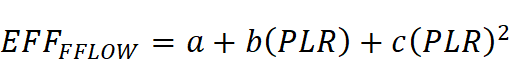
As designed The user shall not be able to select VSD with static pressure reset if the building does not have DDC controls to the zone level. The default fan curve shall be selected from Equation 3 and Table 30 for the type of fan specified in the proposed design.
Where:
| ||||||||
|
Standard Design |
Not applicable for baseline building systems constant volume systems. The curve VSD with static pressure reset fans shall be used for variable volume systems. | ||||||||
|
Standard Design: Existing Buildings |
| ||||||||
|
|
|
|
|
|
Percent Powermin |
|
Fan Type – Control Type |
0.1631 |
1.5901 |
-0.8817 |
0.1281 |
70% |
|
AF or BI riding the curvea |
0.9977 |
-0.659 |
0.9547 |
-0.2936 |
50% |
|
AF or BI with inlet vanes or discharge dampersa |
0.1224 |
0.612 |
0.5983 |
-0.3334 |
50% |
|
FC riding the curvea |
0.3038 |
-0.7608 |
2.2729 |
-0.8169 |
50% |
|
FC with inlet vanesa |
0.1639 |
-0.4016 |
1.9909 |
-0.7541 |
40% |
|
Vane-axial with variable pitch bladesa |
0.070428852 |
0.385330201 |
-0.460864118 |
1.00920344 |
10% |
|
Any fan with VSD |
0.040759894 |
0.08804497 |
-0.07292612 |
0.943739823 |
10% |
|
VSD with static pressure reset |
|
|
|
|
|
|
a: Advanced VAV System Design Guide, California Energy Commission, CEC Publication 500-03-082 A-11, 2007 | |||||
|
Supply Fan Power Index | |
|
Applicability |
Fan systems that use the power-per-unit-flow method |
|
Definition |
The supply fan power (at the motor) per unit of flow |
|
Units |
W/cfm |
|
Input Restrictions |
As designed or specified in the manufacturers’ literature; may only be used for four-pipe fan coil systems |
|
Standard Design |
For FPFC systems, 0.35 W/cfm; for other systems, not applicable. |
|
Standard Design: Existing Buildings |
|
|
Process and Filtration Pressure Drop | |
|
Applicability |
Any system with special requirements for filtration or other process requirements |
|
Definition |
Additional system pressure drop related to application-specific filtration requirements or other process requirements Special documentation requirements may apply. |
|
Units |
List |
|
Input Restrictions |
As designed Default is zero. Special documentation is required to claim any credit for filtration in excess of 1 inch wc. Filtration shall be associated with process requirements (such as clean room or hospital areas). |
|
Standard Design |
Same as proposed but subject to a maximum of 1 inch wc |
|
Standard Design: Existing Buildings |
|
Not applicable for all systems except the four-pipe fan coil (FPFC).
For the FPFC system, the standard design is 0.35 W/cfm.
5.7.3.3 Return/Relief Fans
The baseline building has no return fan. The standard design system has a relief fan only if the standard design system has an economizer.
|
Applicability |
Any system with return ducts or return air plenum |
|
Definition |
A reference to the thermal zone that serves as return plenum or where the return ducts are located |
|
Units |
Text, unique |
|
Input Restrictions |
As designed |
|
Standard Design |
Not applicable |
|
Standard Design: Existing Buildings |
|
|
Return Air Path | |
|
Applicability |
Any system with return ducts or return air plenum |
|
Definition |
Describes the return path for air. Can be ducted return, plenum return, or direct-to-unit. |
|
Units |
List (see above) |
|
Input Restrictions |
As designed |
|
Standard Design |
Applicable when the baseline building has a relief fan. For baseline building systems 1 and 2, the return air path shall be direct-to-unit. For baseline building systems 3 through 11, the baseline building shall be ducted return. |
|
Standard Design: Existing Buildings |
|
|
Return/Relief Fan Design Airflow | |
|
Applicability |
All systems with a return or relief fan |
|
Definition |
The design air flow fan capacity of the return or relief fan(s). This sets the 100 percent fan flow point for the part-load curve (see below). |
|
Units |
Cfm |
|
Input Restrictions |
As designed For relief fans, the return/relief fan design airflow is set equal to the proposed design outside air ventilation rate minus the proposed design exhaust fan design airflow and minus 0.05 cfm/ft2 for pressurization. |
|
Standard Design |
The relief design airflow is equal to the design outside airflow minus the exhaust design air flow rate and minus 0.05 cfm/ft2 for pressurization. |
|
Standard Design: Existing Buildings |
|
|
Applicability |
Any system with return or relief fans that uses the brake horsepower method |
|
Definition |
The design shaft brake horsepower of the return/relief fan(s) |
|
Units |
Brake horsepower (bhp) |
|
Input Restrictions |
As designed The compliance software shall apply the following pre-processing rule to specify the proposed design return/relief fan brake horsepower, based on user input: A standard motor size table (hp) is defined as: 1/12, 1/8, ¼, ½, ¾, 1, 1.5, 2, 3, 5, 7.5, 10, 15, 20, 25, 30, 40, 50, 60, 75, 100, 125, 150, 200. The return/relief fan brake horsepower is determined from user inputs of brake horsepower and motor horsepower for the proposed design, in the same manner as the supply fan brake horsepower. Proposed bhp = min (user bhp, 95 percent x MHPi-1) Where: Proposed bhp is the return/relief fan brake horsepower used in the simulation; User bhp is the actual fan bhp as entered by the user; and MHPi-1 is the motor horsepower of the next smaller motor size from the standard motor size table above; MHPi is the motor size that the user enters for the return/relief fan. See the supply fan brake horsepower descriptor for further details. |
|
Standard Design |
Standard design systems with an economizer shall use relief fans and shall use the static pressure and fan efficiency method. |
|
Standard Design: Existing Buildings |
|
|
Applicability |
All fan systems, except those specified using the power-per-unit-flow method |
|
Definition |
The motor nameplate horsepower of the supply fan |
|
Units |
List choose from standard motor sizes: 1/12, 1/8, ¼, ½, ¾, 1, 1.5, 2, 3, 5, 7.5, 10, 15, 20, 25, 30, 40, 50, 60, 75, 100, 125, 150, 200 |
|
Input Restrictions |
As designed This building descriptor is required for the static pressure or the brake horsepower methods. |
|
Standard Design |
The brake horsepower for the supply fan is this value times the supply fan ratio (see above). |
|
Standard Design: Existing Buildings |
|
|
Return/Relief Design Static Pressure | |
|
Applicability |
Any system with return or relief fans that uses the static pressure method |
|
Definition |
The design static pressure for return fan system. This is important for both fan electric energy usage and duct heat gain calculations. |
|
Units |
Inches of water column (in. H20 gauge) |
|
Input Restrictions |
As designed. The design static pressure for the return fan does not need to be specified if the return fan brake horsepower (bhp) is specified. |
|
Standard Design |
For fans with design airflow less than 10,000 cfm, the static pressure is 0.75”. For fans with design airflow rate 10,000 cfm or greater, the static pressure is 1.0”. |
|
Standard Design: Existing Buildings |
|
|
Return/Relief Fan Efficiency | |
|
Applicability |
Any system with return or relief fans that uses the static pressure method |
|
Definition |
The efficiency of the fan at design conditions. This is the static efficiency and does not include the efficiency loss of the motor. |
|
Units |
Unitless |
|
Input Restrictions |
As designed. The return/relief fan efficiency does not need to be specified if the return fan brake horsepower (bhp) is specified. |
|
Standard Design |
For design airflow less than 10,000 cfm, 40 percent. For design airflow 10,000 cfm or greater, 50 percent. |
|
Standard Design: Existing Buildings |
|
|
Return/Relief Motor Efficiency | |
|
Applicability |
All return fans, except those specified using the power-per-unit-flow method |
|
Definition |
The full-load efficiency of the motor serving the supply fan |
|
Units |
Unitless |
|
Input Restrictions |
As designed. Not applicable when the power-per-unit-flow method is used. |
|
Standard Design |
From ACM Table 29 |
|
Standard Design: Existing Buildings |
|
|
Motor Position | |
|
Applicability |
All return fans |
|
Definition |
The position of the supply fan motor relative to the cooling air stream. The choices are in the air stream or out of the air stream. |
|
Units |
List (see above) |
|
Input Restrictions |
As designed. |
|
Standard Design |
In the air stream |
|
Standard Design: Existing Buildings |
|
|
Fan Part-Flow Power Curve | |
|
Applicability |
All return fans for variable flow fan systems. |
|
Definition |
A part-load power curve which represents the percentage full-load power draw of the supply fan as a function of the percentage full-load air flow. |
|
Units |
Unitless ratio |
|
Input Restrictions |
As designed. The default fan curve shall be selected from Equation 3 and Table 30 for the type of fan specified in the proposed design. |
|
Standard Design |
Not applicable for baseline building systems 1-4. The curve for VSD fans shall be used for baseline building systems that have a return/relief fan. |
|
Standard Design: Existing Buildings |
|
5.7.3.4 Exhaust Fan Systems
The standard design shall track the proposed design exempt process exhaust flow rate up to the prescribed outside air ventilation rate by space type (see Appendix 5.4A for the baseline maximum exhaust rate). Exempt process exhaust includes exhaust from toilets, break rooms, copy rooms and kitchens. Covered process exhaust includes garage ventilation, lab exhaust and exhaust from kitchens with over 5,000 cfm of exhaust. Rules for the baseline covered process exhaust rate and fan power are discussed in the following sections.
Exhaust fan flow is specified and scheduled for each thermal zone. An exhaust fan system may serve multiple thermal zones. For the standard design, total outside air ventilation supply airflow may need to be adjusted so that the design supply airflow for each floor of the building matches the total design exhaust airflow for that floor.
If an exhaust fan system is used in the proposed design as a ventilation system, then an equivalent baseline exhaust fan system is NOT defined, since the baseline has its own specification of a ventilation system that is independent of the proposed.
|
Exhaust Fan Name | |
|
Applicability |
All exhaust systems serving multiple thermal zones |
|
Definition |
A unique descriptor for each exhaust fan. This should be keyed to the construction documents, if possible, to facilitate plan checking. Exhaust rates and schedules at the thermal zone level refer to this name. |
|
Units |
Text, unique |
|
Input Restrictions |
Where applicable, this should match the tags that are used on the plans. |
|
Standard Design |
The baseline building will have an exhaust system that corresponds to the proposed design. However, if the user has specified an exhaust system as the ventilation system an equivalent baseline system will not be modeled since the baseline has its own definition for ventilation systems. The name can be identical to that used for the proposed design or some other appropriate name may be used. |
|
Standard Design: Existing Buildings |
|
|
Applicability |
All exhaust fan systems |
|
Definition |
Compliance software can model fans in three ways. See definition for supply system modeling method. |
|
Units |
List: power-per-unit-flow, static pressure or brake horsepower |
|
Input Restrictions |
As designed |
|
Standard Design |
The baseline building shall use the static pressure method. |
|
Standard Design: Existing Buildings |
|
|
Exhaust Fan Design Airflow | |
|
Applicability |
All exhaust fan systems |
|
Definition |
The rated design air flow rate of the exhaust fan system. This building descriptor defines the 100 percent flow point of the part-flow curve. Actual air flow is the sum of the flow specified for each thermal zone, as modified by the schedule for each thermal zone. |
|
Units |
Cfm |
|
Input Restrictions |
As designed. The total design exhaust flow capacity for building (conditioned space) shall not exceed the sum of building minimum ventilation (outdoor) air flow. Exhaust makeup can be transferred from other zones in the building provided that the total building exhaust rate does not exceed the total minimum outside air flow rate. |
|
Standard Design |
Same as proposed design, but with the same limitations described under input restrictions. The design supply air ventilation rate for zone(s) may need to be adjusted by the software, so that the total design outside air ventilation rate supplied to all zones on a floor equals the total exhaust fan design airflow for all zones on the floor. |
|
Standard Design: Existing Buildings |
|
|
Applicability |
All exhaust fan systems |
|
Definition |
A description of how the exhaust fan(s) are controlled. The options include: •Constant volume •Variable-flow, variable speed drive (VSD) |
|
Units |
List (see above) |
|
Input Restrictions |
As designed, when exhaust fan flow at the thermal zone level is varied through a schedule, one of the variable-flow options shall be specified. |
|
Standard Design |
The baseline building exhaust fan control shall be the same as the proposed design, but subject to the conditions described above. For exhaust fans serving kitchen spaces, the fan control method is constant volume for fans with flow rate 5,000 cfm and below, and variable flow, variable speed drive for fans with flow rate greater than 5,000 cfm. For exhaust fans serving laboratory spaces, the fan control method is variable-flow, variable speed drive when the exhaust flow is 10 ACH or less. If the lab exhaust flow is greater than 10 ACH, the control method is constant volume. |
|
Standard Design: Existing Buildings |
|
|
Exhaust Fan Schedule | |
|
Applicability |
All exhaust fan systems |
|
Definition |
A schedule that indicates when the exhaust fan system is available for operation. Exhaust fan flow is specified at the thermal zone level. |
|
Units |
Data structure: schedule, on/off |
|
Input Restrictions |
For exhaust fans not serving kitchen and lab spaces, the schedule is fixed to match the HVAC availability schedule for the specified occupancy in Appendix 5.4B. For kitchen and lab spaces, the schedule is defined in Appendix 5.4B. |
|
Standard Design |
Specified in Appendix 5.4B for the specified occupancy. |
|
Standard Design: Existing Buildings |
|
|
Exhaust Fan Brake Horsepower | |
|
Applicability |
All exhaust fan systems |
|
Definition |
The design shaft brake horsepower of the exhaust fan(s). |
|
Units |
Brake horsepower (bhp) |
|
Input Restrictions |
As designed |
|
Standard Design |
The compliance software implements a pre-processing rule to specify the proposed design exhaust fan brake horsepower (bhp), based on user input: A standard motor size table (hp) is defined as: 1/12, 1/8, ¼, ½, ¾, 1, 1.5, 2, 3, 5, 7.5, 10, 15, 20, 25, 30, 40, 50, 60, 75, 100, 125, 150, 200 The exhaust fan brake horsepower is determined from user inputs of brake horsepower and motor horsepower for the proposed design, in the same manner as the supply fan brake horsepower. Proposed bhp = max (user bhp, 95 percent x MHPi-1) Where: Proposed bhp is the return/relief fan brake horsepower used in the simulation, User bhp is the actual fan bhp as entered by the user MHPi-1 is the motor horsepower of the next smaller motor size from the standard motor size table above; MHPi is the motor size that the user enters for the exhaust fan See the supply fan brake horsepower descriptor for further details. |
|
Standard Design: Existing Buildings |
|
|
Exhaust Fan Motor Horsepower | |
|
Applicability |
All fan systems, except those specified using the power-per-unit-flow method |
|
Definition |
The motor nameplate horsepower of the supply fan |
|
Units |
List - choose from standard motor sizes: 1/12, 1/8, ¼, ½, ¾, 1, 1.5, 2, 3, 5, 7.5, 10, 15, 20, 25, 30, 40, 50, 60, 75, 100, 125, 150, 200 |
|
Input Restrictions |
As designed This building descriptor is required for the static pressure or the brake horsepower methods. |
|
Standard Design |
Not applicable |
|
Standard Design: Existing Buildings |
|
|
Exhaust Fan Design Static Pressure | |
|
Applicability |
Any system with return or relief fans that uses the static pressure method |
|
Definition |
The design static pressure for exhaust fan system. This is important for both fan electric energy usage and duct heat gain calculations. |
|
Units |
Inches of water column (in. H20) |
|
Input Restrictions |
As designed for exhaust fans not serving kitchens. The design static pressure for the exhaust fan does not need to be specified if the exhaust fan brake horsepower (bhp) is specified. |
|
Standard Design |
For kitchen exhaust fans, the static pressure is fixed at 2.5” wc. For lab exhaust, 4” if six stories or less; or 4.5” if greater than six stories. For all other exhaust fans, the standard design fan W/cfm shall be the same as the proposed design W/cfm. |
|
Standard Design: Existing Buildings |
|
|
Exhaust Fan Efficiency | |
|
Applicability |
Any exhaust fan system that uses the static pressure method |
|
Definition |
The efficiency of the exhaust fan at rated capacity. This is the static efficiency and does not include losses through the motor. |
|
Units |
Unitless |
|
Input Restrictions |
For kitchen exhaust fans, the fan efficiency is prescribed at 50 percent. For all other exhaust fans, as designed. The exhaust fan efficiency does not need to be specified if the return fan brake horsepower (bhp) is specified. |
|
Standard Design |
For kitchen exhaust fans, the fan efficiency is 50 percent, while for lab exhaust it is 62 percent. For all other exhaust fans, the standard design efficiency (and resulting W/cfm) shall be the same as the proposed design efficiency (and resulting W/cfm). |
|
Standard Design: Existing Buildings |
|
|
Exhaust Fan Motor Efficiency | |
|
Applicability |
All exhaust fan systems |
|
Definition |
The full-load efficiency of the motor serving the exhaust fan |
|
Units |
Unitless |
|
Input Restrictions |
As designed |
|
Standard Design |
For exempt process fans other than lab, kitchen, and garage exhaust fans, same as proposed. For process fans, the value is taken. Otherwise, from Table 30. |
|
Standard Design: Existing Buildings |
|
|
Fan Part-Flow Power Curve | |
|
Applicability |
All variable flow exhaust fan systems |
|
Definition |
A part-load power curve that represents the ratio full-load power draw of the exhaust fan as a function of the ratio full-load air flow. |
|
Units |
Unitless ratio |
|
Input Restrictions |
As designed The default fan curve shall be selected from Equation 3 and Table 30 for the type of fan specified in the proposed design. |
|
Standard Design |
The baseline building fan curve shall be selected from Equation 3 and Table 30 for the type of fan specified in the proposed design. |
|
Standard Design: Existing Buildings |
|
|
Exhaust Fan Power Index | |
|
Applicability |
Exhaust systems serving high-rise residential units and hotel/motel guestrooms |
|
Definition |
The fan power of the exhaust fan per unit of flow. This building descriptor is applicable only with the power-per-unit-flow method. |
|
Units |
W/cfm |
|
Input Restrictions |
As designed |
|
Standard Design |
For high-rise residential units and hotel/motel guestrooms, 0.58 W/cfm |
|
Standard Design: Existing Buildings |
|
5.7.3.5 Garage Exhaust Fan Systems
When garage exhaust fan systems are modeled the fans shall be modeled as constant volume fans, with the fan power determined by whether or not the fan has CO controls.
|
Garage Exhaust Fan Name | |
|
Applicability |
All garage exhaust systems |
|
Definition |
A unique descriptor for each garage exhaust fan or fan system Fans with equivalent efficiency and motor efficiencies may be combined and modeled as one fan. |
|
Units |
Text, unique |
|
Input Restrictions |
Where applicable, this should match the tags that are used on the plans. |
|
Standard Design |
The baseline building will have an exhaust system that corresponds to the proposed design. The name can be identical to that used for the proposed design or some other appropriate name may be used. |
|
Standard Design: Existing Buildings |
|
|
Garage Exhaust Fan System Modeling Method | |
|
Applicability |
All exhaust fan systems |
|
Definition |
Software commonly models fans in three ways, see definition for supply system modeling method. |
|
Units |
List power-per-unit-flow, static pressure, or brake horsepower |
|
Input Restrictions |
Brake horsepower method (fixed value) |
|
Standard Design |
The baseline building shall use the power-per-unit-flow method. |
|
Standard Design: Existing Buildings |
|
|
Garage Exhaust Fan Rated Capacity | |
|
Applicability |
All exhaust systems |
|
Definition |
The rated design air flow rate of the garage exhaust fan system |
|
Units |
Cfm |
|
Input Restrictions |
As designed |
|
Standard Design |
Same as proposed design |
|
Standard Design: Existing Buildings |
|
|
Garage Exhaust Fan Control Method | |
|
Applicability |
All exhaust fan systems |
|
Definition |
The control method for the garage exhaust fan. This input determines the fan power for the exhaust fan. No other fan inputs are required. |
|
Units |
List constant volume or CO control |
|
Input Restrictions |
For systems with fan capacity below 10,000 cfm, either constant volume or CO control. For systems with fan capacity above 10,000 cfm, CO control. If constant volume is selected, proposed fan power is as designed. If CO control is selected, proposed fan power is 12.5 percent of the design fan power. |
|
Standard Design |
Same as proposed |
|
Standard Design: Existing Buildings |
|
5.7.3.6 Duct Systems in Unconditioned Space
The details of these modeling rule requirements are under development.
|
Duct Leakage Rate | |
|
Applicability |
Any single-zone systems with ducts in unconditioned space serving zones of 5,000 ft2 or less |
|
Definition |
The leakage rate from the duct system into unconditioned space. All leakage is assumed to occur to unconditioned space (not to outdoors). |
|
Units |
Percentage of design airflow (%) |
|
Input Restrictions |
For new systems: If duct leakage testing is performed as per instructions in the Reference Appendices and certified by a Home Energy Rating System (HERS) rater as designed. If not tested, 15 percent. For existing, altered systems: 15 percent if tested and verified by the HERS procedures in Reference Appendix NA2. If untested or if failed test, 20 percent. |
|
Standard Design |
6 percent for new construction 15 percent for existing, altered systems |
|
Standard Design: Existing Buildings |
|
|
Duct Location | |
|
Applicability |
Single zone, constant volume systems with ducts in unconditioned space, serving 5000 ft2 |
|
Definition |
The duct location is the fraction that is in unconditioned space, in conditioned space, and outdoors |
|
Units |
Three unitless fractions |
|
Input Restrictions |
All in unconditioned space |
|
Standard Design |
All in unconditioned space |
|
Standard Design: Existing Buildings |
|
5.7.4.1 Outside Air Controls
|
Applicability |
All systems with modulating outside air dampers |
|
Definition |
The descriptor is used to limit the maximum amount of outside air that a system can provide as a percentage of the design supply air. It is used where the installation has a restricted intake capacity. |
|
Units |
Ratio |
|
Input Restrictions |
For systems with capacity under 54,000 Btu/h without FDD, the maximum allowed value is 0.9. For all other systems the maximum allowed value is 1. |
|
Standard Design |
1.0 for all systems above 54,000 Btu/h cooling capacity; 0.9 for other systems |
|
Standard Design: Existing Buildings |
|
|
Design Outside Air Flow | |
|
Applicability |
All systems with outside air dampers |
|
Definition |
The rate of outside air that needs to be delivered by the system at design conditions. This input may be derived from the sum of the design outside air flow for each of the zones served by the system. |
|
Units |
Cfm |
|
Input Restrictions |
As designed but no lower than the ventilation rate of the standard design |
|
Standard Design |
Minimum ventilation requirements specified by standard 120(b)2 as the greater of 15 cfm/person and the minimum ventilation rates specified in Appendix 5.4 For systems serving laboratory spaces, the system shall be 100 percent outside air, with ventilation rates as specified by the user, but not less than 6 ACH. See ventilation control method at the zone level. |
|
Standard Design: Existing Buildings |
|
|
Outdoor Air Control Method | |
|
Applicability |
All HVAC systems that deliver outside air to zones |
|
Definition |
The method of determining the amount of outside air that needs to be delivered by the system Each of the zones served by the system report their outside air requirements on an hourly basis. The options for determining the outside air at the zone level are discussed above. This control method addresses how the system responds to this information on an hourly basis. Options include: •Average Flow - The outside air delivered by the system is the sum of the outside air requirement for each zone, without taking into account the position of the VAV damper in each zone. The assumption is that there is mixing between zones through the return air path. •Critical Zone - The critical zone is the zone with the highest ratio of outside air to supply air. The assumption is that there is no mixing between zones. This method will provide greater outside air than the average flow method because when the critical zone sets the outside air fraction at the system, the other zones are getting greater outside air than required. |
|
Units |
List (see above) |
|
Input Restrictions |
As designed |
|
Standard Design |
Average flow |
|
Standard Design: Existing Buildings |
|
5.7.4.2 Air Side Economizers
|
Economizer Control Type | |
|
Applicability |
All systems with an air-side economizer |
|
Definition |
An air-side economizer increases outside air ventilation during periods when refrigeration loads can be reduced from increased outside air flow. The control types include: •No economizer. •Fixed dry-bulb. The economizer is enabled when the temperature of the outside air is equal to or lower than temperature fixed setpoint (e.g., 75°F). •Differential dry-bulb. The economizer is enabled when the temperature of the outside air is lower than the return air temperature. •Differential enthalpy. The economizer is enabled when the enthalpy of the outside air is lower than the return air enthalpy. •Differential dry-bulb and enthalpy. The system shifts to 100 percent outside air or the maximum outside air position needed to maintain the cooling SAT setpoint, when the outside air dry-bulb is less than the return air dry-bulb AND the outside air enthalpy is less than the return air enthalpy. This control option requires additional sensors. •Fixed or dry-bulb enthalpy. The economizer is enabled when the outside air dry-bulb and enthalpy are both below the fixed setpoints for the return air. •Fixed dewpoint and dry-bulb. The system shifts to 100 percent outside air, or the maximum outside air position needed to maintain the SAT setpoint, when the dewpoint of the air and dry-bulb are below the specified setpoints. |
|
Units |
List (see above) |
|
Input Restrictions |
As designed |
|
Standard Design |
The control should be no economizer when the baseline cooling capacity < 54,000 Btu/h and when the standard design cooling system is not a computer room air handling unit (CRAH). Otherwise, the baseline building shall assume an integrated differential dry-bulb economizer. An exception is that economizers shall not be modeled for systems serving high-rise residential or hotel/motel guestroom occupancies. |
|
Standard Design: Existing Buildings |
|
|
Economizer Integration Level | |
|
Applicability |
Airside economizers |
|
Definition |
This input specifies whether or not the economizer is integrated with mechanical cooling. It is up to the modeling software to translate this into software-specific inputs to model this feature. The input could take the following values: •Non-integrated - The system runs the economizer as the first stage of cooling. When the economizer is unable to meet the load, the economizer returns the outside air damper to the minimum position and the compressor turns on as the second stage of cooling. •Integrated - The system can operate with the economizer fully open to outside air and mechanical cooling active (compressor running) simultaneously, even on the lowest cooling stage. |
|
Units |
List (see above) |
|
Input Restrictions |
List non-integrated or integrated |
|
Standard Design |
Integrated for systems above capacity 54,000 Btu/h at Air-Conditioning, Heating, and Refrigeration Institute (AHRI) conditions |
|
Standard Design: Existing Buildings |
|
|
Economizer High Temperature Lockout | |
|
Applicability |
Systems with fixed dry-bulb economizer |
|
Definition |
The outside air setpoint temperature above which the economizer will return to minimum position |
|
Units |
Degrees Fahrenheit (°F) |
|
Input Restrictions |
As designed |
|
Standard Design |
Not applicable |
|
Standard Design: Existing Buildings |
|
|
Economizer Low Temperature Lockout | |
|
Applicability |
Systems with air-side economizers |
|
Definition |
A feature that permits the lockout of economizer operation (return to minimum outside air position) when the outside air temperature is below the lockout setpoint. |
|
Units |
Degrees Fahrenheit (F°) |
|
Input Restrictions |
As designed |
|
Standard Design |
Not applicable |
|
Standard Design: Existing Buildings |
|
|
Applicability |
Systems with differential enthalpy economizers |
|
Definition |
The outside air enthalpy above which the economizer will return to minimum position |
|
Units |
Btu/lb |
|
Input Restrictions |
As designed The default is 28 Btu/lb (high altitude locations may require different setpoints.) The compliance software shall apply a fixed offset and add 2 Btu/lb to the user-entered value. |
|
Standard Design |
No lockout limit |
|
Standard Design: Existing Buildings |
|
5.7.5.1 General
This group of building descriptors applies to all cooling systems.
|
Cooling Source | |
|
Applicability |
All systems |
|
Definition |
The source of cooling for the system; either chilled water, direct expansion (DX), or other |
|
Units |
List (see above) |
|
Input Restrictions |
As designed |
|
Standard Design |
The baseline building cooling source is shown in Table 33 |
|
Standard Design: Existing Buildings |
|
|
Baseline building System |
Cooling Source |
|
Syst-em 1 – PTAC |
Direct expansion (DX) |
|
System 2 – FPFC |
Chilled water |
|
System 3 – PSZ-AC |
Direct expansion (DX) |
|
System 5 – Packaged VAV with Reheat |
Direct expansion (DX) |
|
System 6 – VAV with Reheat |
Chilled water |
|
System 7 – PSZ, Single Zone VAV |
Direct expansion (DX) |
|
System 9 – Heating and Ventilation |
None |
|
System 10 – CRAH Unit for Data Centers |
Chilled water |
|
System 11 – CRAC Unit for Data Centers |
Direct expansion (DX) |
|
Gross Total Cooling Capacity | |||||
|
Applicability |
All cooling systems | ||||
|
Definition |
The total gross cooling capacity (both sensible and latent) of a cooling coil or packaged DX system at AHRI conditions. The building descriptors defined in this chapter assume that the fan is modeled separately, including any heat it adds to the air stream. The cooling capacity specified by this building descriptor should not consider the heat of the fan. | ||||
|
Units |
Btu/h | ||||
|
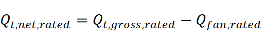
Input Restrictions |
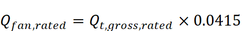
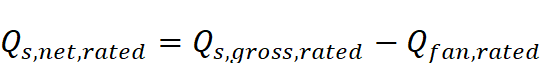
NOT A USER INPUT For packaged equipment that has the fan motor in the air stream such that it adds heat to the cooled air, the software shall calculate the net total cooling capacity as follows:
Where:
If the gross and net total cooling capacities at AHRI conditions are known, the fan heat at rated conditions is the difference between the two values. If the either the gross or net total cooling capacity is unknown, the fan heat at rated conditions shall be accounted for by using Equation 4:
Equation 4 is based on an AHRI rated fan power of 0.365 W/cfm, and a cooling airflow of 400 cfm/ton. If the number of UMLH in the proposed design exceeds 150, the software shall warn the user to resize the equipment. | ||||
|
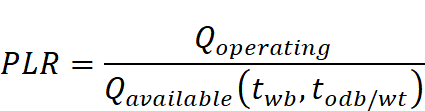
Standard Design |
The gross total cooling capacity of the systems in the baseline building is determined from the standard design net cooling capacity, and from applying the fan power rules above for adjusting for fan heat. | ||||
|
Standard Design: Existing Buildings |
| ||||
|
Gross Total Cooling Capacity | |||||||
|
Applicability |
All cooling systems | ||||||
|
Definition |
The gross sensible cooling capacity of the coil or packaged equipment at AHRI conditions. The building descriptors defined in this chapter assume that the fan is modeled separately, including any heat it adds to the air stream. The cooling capacity specified by this building descriptor should be adjusted to calculate the net sensible cooling capacity, which includes the effect of fan motor heat. The sensible heat ratio (SHR) used by some energy simulation tools can be calculated from the sensible cooling capacity and total cooling capacity: SHR = sensible cooling capacity/total cooling capacity | ||||||
|
Units |
Btu/h | ||||||
|
Input Restrictions |
As designed. For packaged equipment, the compliance software adjusts the user input of gross sensible cooling capacity to account for the effect of fan motor heat as follows:
Where:
If the number of UMLH in the proposed design exceeds 150, the software shall warn the user to resize the equipment. | ||||||
|
Standard Design |
The gross total cooling capacity of the systems serving the baseline building is autosized by the compliance software, and then oversized by 15 percent. Sizing calculations shall be based on 0.5 percent design dry-bulb and mean coincident wet-bulb. | ||||||
|
Standard Design: Existing Buildings |
| ||||||
|
Gross Total Cooling Capacity | |||||||||||||||
|
Applicability |
All cooling systems | ||||||||||||||
|
Definition |
A curve that represents the available total cooling capacity as a function of cooling coil and/or condenser conditions. The common form of these curves is given as follows:
For air-cooled direct expansion:
For water-cooled direct expansion:
For chilled water coils:
Where:
Note: If an air-cooled
unit employs an evaporative condenser, Software may represent the relationship between cooling capacity and temperature in ways other than the equations given above.
| ||||||||||||||
|
Units |
Data structure | ||||||||||||||
|
Input Restrictions |
As designed The equations and coefficients given above are the default. | ||||||||||||||
|
Standard Design |
Use the default curves or equivalent data for other models | ||||||||||||||
|
Standard Design: Existing Buildings |
| ||||||||||||||
|
Coefficient |
Air-Cooled Direct Expansion |
Water-Cooled Direct Expansion |
Chilled Water Coils | ||||
|
Air-Source
|
Air-Source
|
Water-Source
|
Water-Source |
Fan-Coil |
Other Chilled Water | ||
|
a |
1.1839345 |
0.8740302 |
-0.2780377 |
0.9452633 |
0.5038866 |
2.5882585 | |
|
b |
-0.0081087 |
-0.0011416 |
0.0248307 |
-0.0094199 |
-0.0869176 |
-0.2305879 | |
|
c |
0.0002110 |
0.0001711 |
-0.0000095 |
0.0002270 |
0.0016847 |
0.0038359 | |
|
d |
-0.0061435 |
-0.0029570 |
-0.0032731 |
0.0004805 |
0.0336304 |
0.1025812 | |
|
e |
0.0000016 |
0.0000102 |
0.0000070 |
-0.0000045 |
0.0002478 |
0.0005984 | |
|
f |
-0.0000030 |
-0.0000592 |
-0.0000272 |
-0.0000599 |
-0.0010297 |
-0.0028721 | |
|
Note: These curves are the DOE-2.1E defaults, except for Water-Source (Other DX), which is taken from the “ECB Compliance Supplement”, public review draft prepared by the SSPC 90.1 ECB Panel, Version 1.2, March 1996. |
| ||||||
|
Coil Latent Modeling Method | |
|
Applicability |
All DX cooling systems |
|
Definition |
The method of modeling coil latent performance at part-load conditions |
|
Units |
List |
|
Input Restrictions |
One of the following values: Bypass factor – used by DOE-2 based programs NTU-effectiveness – used by EnergyPlus |
|
Standard Design |
Same as proposed |
|
Standard Design: Existing Buildings |
|
|
Coil Bypass Factor | |
|
Applicability |
All DX cooling systems using the bypass factor coil latent modeling method |
|
Definition |
The ratio of air that bypasses the cooling coil at design conditions to the total system airflow |
|
Units |
Ratio |
|
Input Restrictions |
Prescribed values as shown in Table 33. |
|
Standard Design |
Defaults |
|
Standard Design: Existing Buildings |
|
|
System Type |
Default Bypass Factor |
|
Packaged Terminal Air Conditioner and Heat Pumps |
0.241 |
|
Other Packaged Equipment |
0.190 |
|
Multi-Zone Systems |
0.078 |
|
All Other |
0.037 |
|
Coil Bypass Factor Adjustment Curve | |||||||||||||||||||
|
Applicability |
All DX cooling systems using the bypass factor coil latent modeling method | ||||||||||||||||||
|
Definition |
Adjustments for the amount of coil bypass due to the following factors: •Coil airflow rate as a percentage of rated system airflow •Entering air wet-bulb temperature •Entering air dry-bulb temperature •Part load ratio | ||||||||||||||||||
|
Units |
Data structure | ||||||||||||||||||
|
Input Restrictions |
Where applicable, prescribed (fixed) simulation engine defaults based on HVAC system type. The following default values shall be used for the adjustment curves:
Where:
| ||||||||||||||||||
|
Standard Design |
Defaults | ||||||||||||||||||
|
Standard Design: Existing Buildings |
| ||||||||||||||||||
|
Coefficient |
COIL-BF-FFLOW (PTAC) |
COIL-BF-FFLOW (HP) |
COIL-BF-FFLOW (PSZ/other) |
|
a |
-2.277 |
-0.8281602 |
-0.2542341 |
|
b |
5.21140 |
14.3179150 |
1.2182558 |
|
c |
-1.93440 |
-21.8894405 |
0.0359784 |
|
d |
|
9.3996897 |
|
|
Coefficient |
COIL-BF-FT (PTAC) |
COIL-BF-FT (HP) |
COIL-BF-FT (PSZ, other) |
|
a |
-1.5713691 |
-29.9391098 |
1.0660053 |
|
b |
0.0469633 |
0.8753455 |
-0.0005170 |
|
c |
0.0003125 |
-0.0057055 |
0.0000567 |
|
d |
-0.0065347 |
0.1614450 |
-0.0129181 |
|
e |
0.0001105 |
0.0002907 |
-0.0000017 |
|
f |
-0.0003719 |
-0.0031523 |
0.0001503 |
|
Coefficient |
COIL-BF-FPLR (All Systems) |
|
a |
0.00 |
|
b |
1.00 |
|
Cooling Capacity Airflow Adjustment Curve | |||||||||||||||||
|
Applicability |
All DX cooling systems using the NTU effectiveness coil latent modeling method | ||||||||||||||||
|
Definition |
Normalized curve that varies cooling capacity as a function of airflow, which affects system latent capacity | ||||||||||||||||
|
Units |
Data structure | ||||||||||||||||
|
Input Restrictions |
Where applicable, prescribed (fixed) simulation engine defaults based on HVAC system type. The following default values shall be used for the adjustment curves:
Where:
The curve takes the form:
With the following coefficients:
| ||||||||||||||||
|
Standard Design |
Use defaults as described above | ||||||||||||||||
|
Standard Design: Existing Buildings |
| ||||||||||||||||
5.7.5.2 Direct Expansion
|
Direct Expansion Cooling Efficiency | |||||||||
|
Applicability |
Packaged DX equipment | ||||||||
|
Definition |
The cooling efficiency of a direct expansion (DX) cooling system at AHRI rated conditions as a ratio of output over input in Btu/h per W, excluding fan energy. The abbreviation used for this full-load efficiency is Energy Efficiency Ratio (EER). For all unitary and applied equipment where the fan energy is part of the equipment efficiency rating, the EER shall be adjusted as follows:
Where:
| ||||||||
|
Units |
Btu/h-W | ||||||||
|
Input Restrictions
|
As designed, except that the user-entered value must meet mandatory minimum requirements of Table 110.2-A, Table 110.2-B, or Table 110.2-C for the applicable equipment type. When possible, specify the SEER and EER for packaged equipment with cooling capacity less than 65,000 Btu/h from manufacturer’s literature. For equipment with capacity above 65,000 Btu/h, specify EER. When EER is not available for packaged equipment with SEER ratings (AHRI cooling capacity of 65,000 Btu/h or smaller), it shall be calculated as follows:
The default EER shall be calculated by the equation above, but constrained to be no greater than 13. Evaporative cooling systems that pass the requirements of the Western Cooling Challenge may be modeled with an EER as if the equipment were packaged unitary equipment. See Section 5.7.5.4. | ||||||||
|
Standard Design |
Use the minimum cooling efficiency (EER) from tables in Tables 110.2-A, 110.2-B, and 110.2-E in Section 110.2 of the standards. | ||||||||
|
Standard Design: Existing Buildings |
| ||||||||
|
Seasonal Energy Efficiency Ratio | |
|
Applicability |
Packaged DX equipment with AHRI cooling capacity of 65,000 Btu/h or smaller |
|
Definition |
The seasonal cooling efficiency of a direct expansion (DX) cooling system at AHRI rated conditions as a ratio of output over input in Btu/h per W, excluding fan energy. The software must accommodate user input in terms of either the EER or the SEER. For equipment with SEER ratings, EER shall be taken from manufacturers’ data when it is available. |
|
Units |
Btu/h-W |
|
Input Restrictions |
As designed This input is required for small DX systems. The Direct Expansion Cooling Efficiency input is optional for these systems. |
|
Standard Design |
Use the minimum SEER from the 2015 Appliance Efficiency Standards. |
|
Standard Design: Existing Buildings |
|
|
Integrated Energy Efficiency Ratio | |
|
Applicability |
Packaged DX equipment with AHRI cooling capacity of 65,000 Btu/h or greater |
|
Definition |
Integrated Energy Efficiency Ratio This is a SEER that is a composite rating for a range of part-load conditions and different ambient conditions. The rating is determined according to AHRI procedures. Equipment with this rating is subject to mandatory minimum requirements. This input is currently only used for mandatory minimum efficiency checks. |
|
Units |
Btu/h-W |
|
Input Restrictions |
As designed If the IEER rating is below mandatory minimum required levels specified in Section 110.2 of the standards, the compliance run shall fail. |
|
Standard Design |
Not applicable |
|
Standard Design: Existing Buildings |
|
|
Direct Expansion Cooling Efficiency Temperature Adjustment Curve | |||||||||||||||
|
Applicability |
Packaged DX equipment | ||||||||||||||
|
Definition |
A curve that varies the cooling efficiency of a direct expansion (DX) coil as a function of evaporator conditions, condenser conditions, and for small packaged equipment, part-load ratio. For air-cooled DX systems:
For water-cooled DX systems:
Where:
| ||||||||||||||
|
Units |
Data structure | ||||||||||||||
|
Input Restrictions |
User may input curves or use default curves. If defaults are overridden, the software must indicate that supporting documentation is required on the output forms. For DX equipment with a capacity greater than 65,000 Btu/h, the user may not enter data on the temperature dependent equipment performance. However, the ACM compliance software vendor may work with manufacturers to collect such data and build this data into the ACM compliance software. The user may either select equipment for which the ACM compliance software vendor has collected or use the defaults. | ||||||||||||||
|
Standard Design |
For all systems except packaged DX units with cooling capacity <= 65,000 Btu/h, use default curves from Appendix 5.7. For packaged DX units with cooling capacity less than or equal to 65,000 Btu/h that have SEER ratings, the user inputs EER and SEER. The software generates the equipment performance curve based on the pre-defined performance curves specified in Appendix 5.7. | ||||||||||||||
|
Standard Design: Existing Buildings |
| ||||||||||||||
|
Coefficient |
Water-Source (Heat Pump) |
Water-Source (Other) |
Air-Source (PTAC) |
Air-Source (PSZ with Cool Cap <=65,000 Btu/h) |
Air-Source (Other) |
|
a |
2.0280385 |
-1.8394760 |
-0.6550461 |
n/a (see Standard Design) |
-1.0639310 |
|
b |
-0.0423091 |
0.0751363 |
0.0388910 |
n/a |
0.0306584 |
|
c |
0.0003054 |
-0.0005686 |
-0.0001925 |
n/a |
-0.0001269 |
|
d |
0.0149672 |
0.0047090 |
0.0013046 |
n/a |
0.0154213 |
|
e |
0.0000244 |
0.0000901 |
0.0001352 |
n/a |
0.0000497 |
|
f |
-0.0001640 |
-0.0001218 |
-0.0002247 |
n/a |
-0.0002096 |
|
Direct Expansion Part-Load Efficiency Adjustment Curve | |||||||||||||||
|
Applicability |
Packaged systems with DX cooling | ||||||||||||||
|
Definition |
A normalized performance adjustment curve to the rated efficiency (energy input ratio) that describes how the efficiency varies at part-load conditions. At a value of 1 (full load), the normalized efficiency is 1 (same as part-load conditions). The default curves are given as follows as adjustments to the energy input ratio (EIR) :
This curve may take the form of a part-load factor (PLF) or EIR-FLPR, which is the fraction of time that the unit must run to meet the part-load for that hour. For example, at 40 percent of full load, the equipment might need to run 50 percent of the hour for cycling losses. Note: For small packaged equipment with SEER ratings <65,000 Btu/h, the part-load efficiency curve is set to no degradation, since the part-load degradation is built into the direct expansion cooling efficiency temperature adjustment curve. Default curves are provided for the different major classes of equipment. Where:
| ||||||||||||||
|
Units |
Coefficients (three for a quadratic, or up to four for a cubic) | ||||||||||||||
|
Input Restrictions |
The coefficients should sum to 1 (within a small tolerance). This corresponds to a curve output of 1 for an input of 1. | ||||||||||||||
|
Standard Design |
The baseline part-load efficiency adjustment curves are shown in the tables below. | ||||||||||||||
|
Standard Design: Existing Buildings |
| ||||||||||||||
|
Coefficient |
Water-Source |
Water-Source |
Air-Source (PTAC) |
Air-Source (PSZ with Cap <65,000 Btu/h) |
Air-Source (Other) |
|
a |
0.1250000 |
0.2012301 |
0.1250000 |
0 |
0.2012301 |
|
b |
0.8750000 |
-0.0312175 |
0.8750000 |
1 |
-0.0312175 |
|
c |
0.0000000 |
1.9504979 |
0.0000000 |
0 |
1.9504979 |
|
d |
0.0000000 |
-1.1205105 |
0.0000000 |
0 |
-1.1205105 |
|
Coefficient |
Water-Source |
Water-Source |
Air-Source (PTAC) |
Air-Source (PSZ with Cap <65,000 Btu/h) |
Air-Source (Other) | |
|
a |
0.85 |
0 |
0.85 |
1 |
0 | |
|
b |
0.15 |
5.1091 |
0.15 |
0 |
5.1091 | |
|
c |
0 |
-8.5515 |
0 |
0 |
-8.5515 | |
|
d |
0 |
4.4744 |
0 |
0 |
4.4744 | |
|
Number of Cooling Stages | |
|
Applicability |
Single zone VAV systems and DX systems with multiple stages |
|
Definition |
This applies to single zone VAV and any HVAC systems with multiple compressors or multiple discrete stages of cooling. This system is a packaged unit with multiple compressors and a two-speed or variable-speed fan. Systems with unequally sized compressors may have additional cooling stages. |
|
Units |
None (Integer) |
|
Input Restrictions |
As designed |
|
Standard Design |
The standard design shall be two for the single zone VAV baseline and packaged VAV baseline. |
|
Standard Design: Existing Buildings |
|
|
Total Cooling Capacity by Stage | |
|
Applicability |
Single zone VAV systems and DX systems with multiple stages |
|
Definition |
This provides the total cooling capacity of each cooling stage, at AHRI rated conditions. The capacity is expressed as an array, with each entry a fraction of the total rated cooling capacity for the unit. For example, if the stage cooling capacity is 4 tons (48,000 Btu/h) and the total cooling capacity is 8 tons (96,000 Btu/h), the capacity is expressed as “0.50” for that stage. |
|
Units |
Array of fractions |
|
Input Restrictions |
As designed |
|
Standard Design |
The default shall be (0.50,1) for the single zone VAV baseline. |
|
Standard Design: Existing Buildings |
|
|
Sensible Cooling Capacity by Stage | |
|
Applicability |
Single zone VAV systems and DX systems with multiple stages |
|
Definition |
This provides the sensible cooling capacity of each cooling stage, at AHRI rated conditions. The capacity is expressed as an array, with each entry a fraction of the total rated sensible cooling capacity for the unit. For example, if the stage sensible cooling capacity is 3.5 tons (42,000 Btu/h) and the total sensible cooling capacity is 7 tons (72,000 Btu/h), the capacity is expressed as "0.5" for that stage." |
|
Units |
Array of fractions |
|
Input Restrictions |
As designed |
|
Standard Design |
The default shall be (0.50, 1) for the single zone VAV baseline. |
|
Standard Design: Existing Buildings |
|
|
Supply Air Temperature Reset by Stage | |
|
Applicability |
Single zone VAV systems with supply air temperature control method set to staged control |
|
Definition |
This provides the cooling supply air temperature setpoint deviation from the cooling design supply air temperature, specified in the building descriptor cooling supply air temperature. The temperature reset is expressed as an array, with each entry a deviation from the design supply air temperature. For example, an entry of “5” for a stage would indicate a 5°F reset (for example, 60°F from 55°F). |
|
Units |
Array of temperature differences, in °F |
|
Input Restrictions |
As designed |
|
Standard Design |
Not applicable |
|
Standard Design: Existing Buildings |
|
|
Number of Heating Stages | |
|
Applicability |
Single zone VAV systems and DX systems with multiple stages |
|
Definition |
The number of heating stages provided by the system. Multiple stages could be provided via a heat pump or via a multiple-stage gas furnace. |
|
Units |
Integer |
|
Input Restrictions |
As designed |
|
Standard Design |
1 |
|
Standard Design: Existing Buildings |
|
|
Heating Capacity by Stage | |
|
Applicability |
Single zone VAV systems and DX systems with multiple stages |
|
Definition |
This provides the total heating capacity of each heating stage, at AHRI rated conditions. The capacity is expressed as an array, with each entry a fraction of the total rated cooling capacity for the unit. For example, if the stage heating capacity is 48,000 Btu/h and the heating capacity is 96,000 Btu/h, the capacity is expressed as “0.50” for that stage. |
|
Units |
Array of fractions |
|
Input Restrictions |
As designed |
|
Standard Design |
Not applicable |
|
Standard Design: Existing Buildings |
|
|
Heating Supply Air Temperature by Stage | |
|
Applicability |
Single zone VAV systems and DX systems with multiple stages |
|
Definition |
This provides the heating supply air temperature setpoint deviation from the design heating supply air temperature, specified in the building descriptor heating supply air temperature. The temperature reset is expressed as an array, with each entry a deviation from the design supply air temperature. For example, an entry of “-10” for a stage would indicate a 10°F reset (for example, 95°F from 105°F). |
|
Units |
Array of temperature differences, in °F |
|
Input Restrictions |
As designed |
|
Standard Design |
Not applicable |
|
Standard Design: Existing Buildings |
|
|
Supply Fan Low Speed Ratio | |
|
Applicability |
Single zone VAV systems and DX systems with multiple stages and two-speed fans |
|
Definition |
This specifies the low fan speed setting on a single zone VAV system or DX system with multiple cooling stages. |
|
Units |
None (fraction) |
|
Input Restrictions |
As designed |
|
Standard Design |
The default shall be the greater of 0.50 or the minimum outside air fraction for the single zone VAV baseline. |
|
Standard Design: Existing Buildings |
|
|
Supply Fan Low Power Ratio | |
|
Applicability |
Single sone VAV systems and DX systems with multiple stages and two-speed fans |
|
Definition |
This specifies the fraction of full load fan power corresponding to low fan speed operation on a single zone VAV system or DX system with multiple cooling stages. |
|
Units |
None (fraction) |
|
Input Restrictions |
As designed |
|
Standard Design |
The default shall be 0.30, or the minimum power ratio calculated by applying the minimum outside air fraction to the “any fan with VSD” curve, for the single zone VAV baseline. |
|
Standard Design: Existing Buildings |
|
|
Minimum Unloading Ratio | |
|
Applicability |
Packaged DX systems |
|
Definition |
The fraction of total cooling capacity below which compressor(s) must cycle on and off to meet the cooling load. Below the minimum unloading ratio, part-load efficiency is reduced. Also, below the minimum unloading ratio, the economizer will not operate in a fully integrated mode with compressor cooling. |
|
Units |
Ratio |
|
Input Restrictions |
As designed The user must enter this descriptor for each DX cooling system. If hot-gas bypass is not employed, a value of 0 may be entered. |
|
Standard Design |
0.25 for units with a peak total cooling capacity greater than or equal to 240 kBtu/h; 0.35 for units with a peak cooling capacity greater than or equal to 65 kBtu/h and less than 240 kBtu/h |
|
Standard Design: Existing Buildings |
|
|
Minimum Hot-Gas Bypass Ratio | |
|
Applicability |
Packaged systems which use hot-gas bypass during low load conditions |
|
Definition |
The lower end of the hot-gas bypass operating range. The percentage of peak cooling capacity below which hot-gas bypass will no longer operate (i.e., the compressor will cycle). |
|
Units |
Ratio |
|
Input Restrictions |
0 |
|
Standard Design |
0 |
|
Standard Design: Existing Buildings |
|
|
Condenser Type | |
|
Applicability |
All direct expansion systems including heat pumps |
|
Definition |
The type of condenser for a DX cooling system The choices are: •Air-cooled •Water-cooled •Air-cooled with evaporative pre-cooler |
|
Units |
List (see above) |
|
Input Restrictions |
As designed |
|
Standard Design |
Based on the prescribed system type Refer to the HVAC System Map in section 5.7.1. Air-cooled for systems 1 (PTAC), 3, (PSZ), 5 (PVAV) and 11 (CRAC). Not applicable for other standard design systems. |
|
Standard Design: Existing Buildings |
|
|
Condenser Flow Type | |
|
Applicability |
All direct expansion systems including heat pumps |
|
Definition |
Describes water flow control for a water-cooled condenser. The choices are: •Fixed flow •Two-position •Variable flow |
|
Units |
List (see above) |
|
Input Restrictions |
Default to fixed flow If the variable-flow is selected, the software must indicate that supporting documentation is required on the output forms. |
|
Standard Design |
Two-position |
|
Standard Design: Existing Buildings |
|
|
Supplementary DX Cooling Unit | |
|
Applicability |
Required when user-defined natural ventilation or evaporative cooling systems have excessive unmet load hours |
|
Definition |
The specification of a supplementary DX cooling system that must be used when the user-defined cooling system results in unmet load hours exceeding 150 for any zone. |
|
Units |
List |
|
Input Restrictions |
The user shall input the following system characteristics, with one unit for each zone: Total cooling capacity (Btu/h) Total heating capacity (Btu/h) The compliance software shall define the following prescribed system characteristics: Efficiency - minimum efficiency from Table 110.2-A, based on cooling capacity System airflow - 350 cfm/ton cooling Economizer - none Design supply air temperature - 55°F Supply air temperature control - fixed Design heating supply air temperature - 105°F |
|
Standard Design |
Not applicable |
|
Standard Design: Existing Buildings |
|
5.7.5.3 Evaporative Cooler
This is equipment that pre-cools the outside air that is brought into the building. It may be used with any type of cooling system that brings in outside air. This equipment is not applicable for the baseline building.
|
Evaporative Cooling Type | |
|
Applicability |
Systems with evaporative cooling |
|
Definition |
The type of evaporative pre-cooler, including: •None •Non-integrated direct •Non-integrated indirect •Non-integrated direct/Indirect •Integrated direct •Integrated indirect •Integrated direct/indirect An integrated cooler can operate together with compressor or CHW cooling. A non-integrated cooler will shut down the evaporative cooling whenever it is unable to provide 100 percent of the cooling required. Direct evaporative cooling can only be applied to the outside air. Indirect evaporative cooling can be applied to outside air or return air. |
|
Units |
None |
|
Input Restrictions |
As designed |
|
Standard Design |
Not applicable |
|
Standard Design: Existing Buildings |
|
|
Evaporative Cooling System Capacity | |
|
Applicability |
Systems with evaporative cooling |
|
Definition |
The total sensible cooling capacity of the evaporative cooling system at design outdoor dry-bulb conditions. This value may be derived from other inputs of supply fan design air rated capacity (Section 5.7.3), direct stage effectiveness, indirect stage effectiveness, and design outdoor conditions. |
|
Units |
None |
|
Input Restrictions |
Not applicable Derived input. If there are excessive unmet load hours in any zone served by the evaporative cooling system, a supplementary DX cooling unit must be defined by the user. See Section 5.7.5.2. |
|
Standard Design |
Not applicable |
|
Standard Design: Existing Buildings |
|
|
Direct Stage Effectiveness | |||||||||
|
Applicability |
Systems with evaporative cooling | ||||||||
|
Definition |
The effectiveness of the direct stage of an evaporative cooling system. Effectiveness is defined as:
Where:
| ||||||||
|
Units |
Numeric (0 ≤ EFF ≤1) | ||||||||
|
Input Restrictions |
As designed | ||||||||
|
Standard Design |
Not applicable | ||||||||
|
Standard Design: Existing Buildings |
| ||||||||
|
Indirect Stage Effectiveness | |||||||||
|
Applicability |
Systems with evaporative cooling | ||||||||
|
Definition |
The effectiveness of the indirect stage of an evaporative cooling system. Effectiveness is defined as:
Where:
| ||||||||
|
Units |
Numeric (0 ≤ EFF ≤1) | ||||||||
|
Input Restrictions |
As designed | ||||||||
|
Standard Design |
Not applicable | ||||||||
|
Standard Design: Existing Buildings |
| ||||||||
|
Evaporative Cooling Performance Curves | |||||||||
|
Applicability |
Systems with evaporative cooling | ||||||||
|
Definition |
A curve that varies the evaporative cooling effectiveness as a function of primary air stream airflow. The default curves are given as:
Where:
| ||||||||
|
Units |
Data structure | ||||||||
|
Input Restrictions |
User may input curves or use default curves. If defaults are overridden, the software must indicate that supporting documentation is required on the output forms. | ||||||||
|
Standard Design |
Not applicable | ||||||||
|
Standard Design: Existing Buildings |
| ||||||||
|
Coefficient |
Direct |
Indirect |
|
A |
1.1833000 |
1.0970000 |
|
B |
-0.2575300 |
-0.1650600 |
|
C |
0.0742450 |
0.0680690 |
|
Auxiliary Evaporative Cooling Power | |
|
Applicability |
Systems with evaporative cooling |
|
Definition |
The auxiliary energy of the indirect evaporative cooler fan, and the pumps for both direct and indirect stages |
|
Units |
Watts |
|
Input Restrictions |
As designed |
|
Standard Design |
Not applicable |
|
Standard Design: Existing Buildings |
|
|
Evaporative Cooling Scavenger Air Source | |
|
Applicability |
Systems with evaporative cooling |
|
Definition |
The source of scavenger air for an indirect section of an evaporative cooler. Options include: •Return air •Outside air |
|
Units |
List (see above) |
|
Input Restrictions |
As designed |
|
Standard Design |
Not applicable |
|
Standard Design: Existing Buildings |
|
5.7.5.4 Western Cooling Challenge Equipment
A special credit is available in the ACM Reference Manual for equipment (including evaporative equipment) that meets efficiency and water use requirements of the Western Cooling Challenge (WCC), a program of the Western Cooling Efficiency Center. This compliance option triggers an exceptional condition and documentation requirements. See Chapter 3 of the ACM Reference Manual for more information.
This equipment is modeled as high-efficiency DX equipment, with a constant volume fan, integrated economizer, and fixed performance curve. Unlike the input model for a packaged DX equipment, the WCC equipment has many building descriptor inputs fixed (prescribed). Rather than listing the WCC input restrictions as an option within each building descriptor, all requirements for WCC equipment are contained in this section.
Heating equipment must be specified separately, as the WCC test procedure does not include heating conditions. The heating system may be any system other than a heat pump.
|
Building Descriptor |
Section |
Proposed Input |
|
System Type |
5.7.1 |
PSZ-AC and PSZVAV-AC only |
|
Cooling Supply Air Temperature |
5.7.2.2 |
20°F below return air temperature |
|
Cooling Supply Air Temperature Control |
5.7.2.2 |
Fixed (single zone system) |
|
Heating Supply Air temperature |
5.7.2.3 |
105°F |
|
Heating Supply Air Temperature Control |
5.7.2.3 |
Fixed (constant) |
|
Supply Fan Design Air Rated Capacity |
5.7.3 |
400 cfm/ton |
|
Fan Control Method |
5.7.3 |
Constant Volume |
|
Supply Fan Power Index |
5.7.3.2 |
0.365 W/cfm |
|
Maximum Outside Air Ratio |
5.7.4.1 |
1 |
|
Design Outside Air Flow |
5.7.4.1 |
(as designed) |
|
Economizer Control Type |
5.7.4.2 |
Differential dry-bulb |
|
Economizer Integration Level |
5.7.4.2 |
Integrated |
|
Economizer High Temperature Lockout |
5.7.4.2 |
n/a |
|
Economizer low temperature lockout |
5.7.4.2 |
n/a |
|
Cooling Source |
5.7.5 |
DX |
|
Total Cooling Capacity |
5.7.5 |
As designed (NOTE: If there are UMLH, the user will have to enter a larger capacity system, or add a supplemental DX unit with standard efficiency (EER~11) to meet cooling load.) |
|
Sensible Cooling Capacity |
5.7.5 |
As designed |
|
Cooling Capacity Adjustment Curves |
5.7.5 |
Use air-cooled DX defaults |
|
Coil Bypass Factor (if used) |
5.7.5 |
0.190 |
|
Direct Expansion Cooling Efficiency |
5.7.5.2 |
As designed (User enters EER from WCC test and software makes adjustment for EER, removing fan power from efficiency as needed.) |
|
Seasonal Energy Efficiency Ratio |
5.7.5.2 |
n/a |
|
Direct Expansion Cooling Efficiency Temperature Adjustment Curve |
5.7.5.2 |
Use default curve |
|
Direct Expansion Part-Load Efficiency Adjustment Curve |
5.7.5.2 |
Use default curve |
|
Refrigerant Charge Factor |
5.7.5.2 |
1 |
|
Airflow Adjustment Factor |
5.7.5.2 |
1 |
|
Duct Leakage Rate |
5.7.5.2 |
As designed (for qualifying spaces) |
|
Minimum Unloading Ratio |
5.7.5.2 |
0.25 (units > 240 kBtu/h) 0.35 (units >= 65 kBtu/h and < 120 kBtu/h) |
|
Cooling Setpoint Schedule |
5.4 |
Use default schedule for space type (this will be 75°F when occupied, in most cases) |
|
Heating |
|
|
|
Heating Source |
5.7.6.1 |
As designed (but heat pump not allowed) |
|
Preheat Coil |
5.7.6.2 |
No preheat coil |
|
Heating Coil Capacity |
5.7.6.3 |
As designed |
|
Furnace Capacity |
5.7.6.4 |
As designed |
|
Furnace Fuel Heating Efficiency |
5.7.6.3 |
As designed |
|
Furnace Fuel Heating Part Load Efficiency Curve |
5.7.6.4 |
Fixed default curve |
|
Furnace Fuel Heating Pilot |
5.7.6.4 |
0 |
|
Furnace Fuel Heating Fan/Auxiliary |
5.7.6.4 |
n/a |
|
Heat recovery |
5.7.6.6 |
Not allowed for this credit |
|
Humidity Controls and Devices |
5.7.7 |
None |
5.7.5.5 Evaporative Condenser
|
Evaporative Condenser Power | |
|
Applicability |
Direct expansion systems with an evaporatively cooled condenser |
|
Definition |
The power of the evaporative precooling unit; includes any pump(s) and/or fans that are part of the precooling unit |
|
Units |
Watts |
|
Input Restrictions |
As designed |
|
Standard Design |
Not applicable |
|
Standard Design: Existing Buildings |
|
|
Evaporative Condenser Effectiveness | |||||||||
|
Applicability |
Direct expansion systems with an evaporatively cooled condenser | ||||||||
|
Definition |
The effectiveness of the evaporative precooling unit for a condenser. Effectiveness is defined as:
Where:
| ||||||||
|
Units |
Ratio | ||||||||
|
Input Restrictions |
As designed | ||||||||
|
Standard Design |
Not applicable | ||||||||
|
Standard Design: Existing Buildings |
| ||||||||
|
Evaporative Condenser Operation Range | |||||
|
Applicability |
Direct expansion systems with an evaporatively cooled condenser | ||||
|
Definition |
The temperature range within which the evaporative condenser operates. Two values are provided:
| ||||
|
Units |
Degrees Fahrenheit (°F) | ||||
|
Input Restrictions |
As designed | ||||
|
Standard Design |
Not applicable | ||||
|
Standard Design: Existing Buildings |
| ||||
5.7.5.6 Four-Pipe Fan Coil Systems
This section contains building descriptors required to model four-pipe fan coil systems. Note that this system requires an outside air ventilation source to serve the zones and that an airside economizer is not available.
The fan coil fans shall be modeled with the power-per-unit-flow method. The standard design fan power shall be 0.35 W/cfm when the four-pipe fan coil is the standard design system. See the supply fan information, which can be found in the ACM Reference Manual, section 5.7.3.2.
Supply air flow rates are set at the zone level. Chilled water flow rates are set according to the rules in section 5.8.5 on pumps.
Additional HVAC components (chiller, boiler, pumps) are needed to fully define this system. If a water-side economizer is specified with this system, refer to section 5.8.4 for a list of applicable building descriptors.
|
Capacity Control Method | |
|
Applicability |
Four-pipe fan coil systems |
|
Definition |
The control method for the fan coil unit at the zone. The following choices are available: •Constant Fan Variable Flow •Cycling Fan •Variable Fan Constant Flow •Variable Fan Variable Flow |
|
Units |
List (with choices above) |
|
Input Restrictions |
Not a user input. It comes from building descriptors for fan control and chiller loop flow control |
|
Standard Design |
Cycling Fan |
|
Standard Design: Existing Buildings |
|
|
Rated Gross Capacity | |
|
Applicability |
Four-pipe fan coil systems and chilled beams |
|
Definition |
The gross cooling capacity of the cooling coil |
|
Units |
Btu/h |
|
Input Restrictions |
None |
|
Standard Design |
Not applicable |
|
Standard Design: Existing Buildings |
|
|
Cooling Coil Design Flow rate | |
|
Applicability |
Four-pipe fan coil systems and chilled beams |
|
Definition |
The design flow rate of the cooling coil |
|
Units |
Gallons per minute (gpm) |
|
Input Restrictions |
None |
|
Standard Design |
Not applicable |
|
Standard Design: Existing Buildings |
|
|
Pressure Drop | |
|
Applicability |
Four-pipe fan coil systems and chilled beams |
|
Definition |
The pressure drop across the cooling coil |
|
Units |
ft. wg |
|
Input Restrictions |
None |
|
Standard Design |
Not applicable |
|
Standard Design: Existing Buildings |
|
|
Chilled Beam Induced Air Flow | |
|
Applicability |
Active and passive chilled beams |
|
Definition |
The induced air flow rate across the coil |
|
Units |
Cfm |
|
Input Restrictions |
None |
|
Standard Design |
Not applicable |
|
Standard Design: Existing Buildings |
|
|
Capacity Control Method | |
|
Applicability |
Four-pipe fan coil systems |
|
Definition |
The control method for the fan coil unit at the zone. The following choices are available: •Constant Fan Variable Flow •Cycling Fan •Variable Fan Constant Flow •Variable Fan Variable Flow |
|
Units |
List (with choices above) |
|
Input Restrictions |
Not a user input – derived from building descriptors for fan control and chiller loop flow control. |
|
Standard Design |
Cycling Fan |
|
Standard Design: Existing Buildings |
|
5.7.5.7 Radiant Cooling
This section describes a floor-based radiant cooling system and the inputs required for Title 24 compliance evaluation.
|
Hydronic Tubing Length | |
|
Applicability |
Floor-based radiant cooling systems |
|
Definition |
The length of the hydronic tubing in the slab |
|
Units |
ft |
|
Input Restrictions |
As designed |
|
Standard Design |
Not applicable |
|
Standard Design: Existing Buildings |
|
|
Hydronic Tubing Inside Diameter | |
|
Applicability |
Floor-based radiant cooling systems |
|
Definition |
The inside diameter of the hydronic tubing in the slab |
|
Units |
Ft |
|
Input Restrictions |
As designed, between a minimum of ½” and a maximum of ¾” |
|
Standard Design |
Not applicable |
|
Standard Design: Existing Buildings |
|
|
Temperature Control Type | |
|
Applicability |
Floor-based radiant cooling systems |
|
Definition |
The temperature used for control (operative temperature, mean air temperature, mean radiant temperature, Outdoor Dry Bulb (ODB), or Outdoor Wet Bulb (OWB) |
|
Units |
None |
|
Input Restrictions |
Fixed at mean air temperature for compliance calculations |
|
Standard Design |
Not applicable |
|
Standard Design: Existing Buildings |
|
|
Cooling Control Temperature | |
|
Applicability |
Variable flow systems |
|
Definition |
The temperature used for control (operative temperature, mean air temperature, mean radiant temperature, ODB, or OWB) |
|
Units |
None |
|
Input Restrictions |
Fixed at mean air temperature for compliance calculations |
|
Standard Design |
Not applicable |
|
Standard Design: Existing Buildings |
|
|
Condensation Control Type | |
|
Applicability |
Floor-based radiant cooling systems |
|
Definition |
The temperature used for control (operative temperature, mean air temperature, mean radiant temperature, ODB, or OWB) |
|
Units |
None |
|
Input Restrictions |
Fixed at mean air temperature for compliance calculations |
|
Standard Design |
Not applicable |
|
Standard Design: Existing Buildings |
|
|
Condensation Control Dewpoint Offset | |
|
Applicability |
Floor-based radiant cooling systems |
|
Definition |
The temperature difference above dewpoint that is the minimum cold water supply temperature |
|
Units |
None |
|
Input Restrictions |
Fixed at 2°F above dewpoint |
|
Standard Design |
Not applicable |
|
Standard Design: Existing Buildings |
|
|
Rated Pump Power Consumption | |
|
Applicability |
Floor-based radiant cooling systems |
|
Definition |
The rated pump power at design conditions |
|
Units |
Watts |
|
Input Restrictions |
As designed |
|
Standard Design |
Not applicable |
|
Standard Design: Existing Buildings |
|
|
Motor Efficiency | |
|
Applicability |
Floor-based radiant cooling systems |
|
Definition |
The pump motor efficiency |
|
Units |
Decimal fraction |
|
Input Restrictions |
As designed |
|
Standard Design |
Default motor efficiency from Table N2-20 (table numbering may change) based on motor nameplate hp |
|
Standard Design: Existing Buildings |
|
|
Fraction of Motor Heat to Fluid | |
|
Applicability |
Floor-based radiant cooling systems |
|
Definition |
Fraction of the heat from the motor inefficiencies that enters the fluid stream |
|
Units |
None |
|
Input Restrictions |
As designed; default is 0 |
|
Standard Design |
Not applicable |
|
Standard Design: Existing Buildings |
|
|
Cooling High Water Temperature | |
|
Applicability |
Floor-based radiant cooling systems |
|
Definition |
The high temperature used for control. If the water temperature is above the high temperature, the control temperature is set to the low control temperature. |
|
Units |
°F |
|
Input Restrictions |
As designed |
|
Standard Design |
Not applicable |
|
Standard Design: Existing Buildings |
|
|
Cooling Low Water Temperature | |
|
Applicability |
Floor-based radiant cooling systems |
|
Definition |
The temperature used for control of the water temperature. If the water temperature of the radiant cooling is below this temperature, cooling is disabled. |
|
Units |
°F |
|
Input Restrictions |
Fixed at 55°F |
|
Standard Design |
Not applicable |
|
Standard Design: Existing Buildings |
|
|
Condensation Control Type | |
|
Applicability |
Floor-based radiant cooling systems |
|
Definition |
The simulation program may have a means of detecting when condensation is likely to occur on floor surfaces in the space. When this occurs, the simulation can shut off the system to prevent condensation from occurring. |
|
Units |
List none, simple, or variable |
|
Input Restrictions |
As designed |
|
Standard Design |
Not applicable |
|
Standard Design: Existing Buildings |
|
5.7.5.8 Chilled Beams
Active and passive chilled beams can be modeled, in a similar manner to four-pipe fan coil systems. Active chilled beams are modeled as a four-pipe fan coil object. The zone fan for the beam is not specified by the user, but is internally added to the compliance model with no fan power.
|
Chilled Beam Name | |
|
Applicability |
Chilled beams |
|
Definition |
A unique name designating the chilled beam |
|
Units |
None |
|
Input Restrictions |
None |
|
Standard Design |
Not applicable |
|
Standard Design: Existing Buildings |
|
|
Chilled Beam Type | |
|
Applicability |
Chilled beams |
|
Definition |
Specification of the beam as active or passive |
|
Units |
List: •Active •Passive
|
|
Input Restrictions |
None |
|
Standard Design |
Not applicable |
|
Standard Design: Existing Buildings |
|
|
Design Cooling Capacity | |
|
Applicability |
Chilled beams |
|
Definition |
The designed cooling capacity of the chilled beam |
|
Units |
Btu/h |
|
Input Restrictions |
None |
|
Standard Design |
Not applicable |
|
Standard Design: Existing Buildings |
|
|
Design Chilled Water Temperature | |
|
Applicability |
Chilled beams |
|
Definition |
The minimum supplied chilled water temperature to the beam. This is typically at least 2°F higher than the space dewpoint temperature at design conditions, to prevent condensation. |
|
Units |
°F |
|
Input Restrictions |
None |
|
Standard Design |
Not applicable |
|
Standard Design: Existing Buildings |
|
|
Maximum Chilled Water Temperature | |
|
Applicability |
Chilled beams |
|
Definition |
The maximum supplied chilled water temperature to the beam. This allows for chilled water temperature reset at the source. |
|
Units |
°F |
|
*Input Restrictions |
Should be equal to or greater than the design chilled water temperature |
|
Standard Design |
Not applicable |
|
Standard Design: Existing Buildings |
|
|
Active Beam Maximum Primary Flow Rate | |
|
Applicability |
Chilled beams |
|
Definition |
The design flow rate of the active fan |
|
Units |
Cfm |
|
Input Restrictions |
As designed |
|
Standard Design |
Not applicable |
|
Standard Design: Existing Buildings |
|
|
Active Beam Induced Air Rate | |
|
Applicability |
Active chilled beams |
|
Definition |
The rate at which induced air is drawn through the chilled beam. The total airflow across the beam is the sum of the maximum primary flow rate and the active beam induced air flow rate. |
|
Units |
Cfm |
|
Input Restrictions |
None |
|
Standard Design |
Not applicable |
|
Standard Design: Existing Buildings |
|
|
Active Fan Static Pressure | |
|
Applicability |
Chilled beams |
|
Definition |
The design status of the active fan |
|
Units |
in. wc |
|
Input Restrictions |
None |
|
Standard Design |
Not applicable |
|
Standard Design: Existing Buildings |
|
|
Active Fan Static Efficiency | |
|
Applicability |
Chilled beams |
|
Definition |
The fan static efficiency |
|
Units |
in. wc |
|
Input Restrictions |
Between 0 and 1 |
|
Standard Design |
Not applicable |
|
Standard Design: Existing Buildings |
|
|
Active Fan Motor Efficiency | |
|
Applicability |
Chilled beams |
|
Definition |
The motor efficiency of the fan |
|
Units |
in. wc |
|
Input Restrictions |
None |
|
Standard Design |
Not applicable |
|
Standard Design: Existing Buildings |
|
|
Chilled Beam Heating Capacity | |
|
Applicability |
Chilled beams |
|
Definition |
The heating capacity of the chilled beam |
|
Units |
Btu/h |
|
Input Restrictions |
None; defaults to 1 if no heating |
|
Standard Design |
Not applicable |
|
Standard Design: Existing Buildings |
|
|
Chilled Beam Heating Source | |
|
Applicability |
Chilled beams |
|
Definition |
Defaults to electric resistance, whether there is heating provided by the beam or not |
|
Units |
None |
|
Input Restrictions |
Electric resistance |
|
Standard Design |
Not applicable |
|
Standard Design: Existing Buildings |
|
5.7.6.1 General
|
Heating Source | |
|
Applicability |
All systems that provide heating |
|
Definition |
The source of heating for the heating and preheat coils The choices are: •Hot water •Steam •Electric resistance •Electric heat pump •Gas furnace •Gas heat pump (optional feature) •Oil furnace •Heat recovery |
|
Units |
List (see above) |
|
Input Restrictions |
As designed |
|
Standard Design |
Based on the prescribed system type. Refer to the HVAC system map in Section 5.1.2. |
|
Standard Design: Existing Buildings |
|
|
Baseline Building System |
Heating Source |
|
System 1 – PTAC |
Hot water |
|
System 2 – FPFC |
Hot water |
|
System 3 – PSZ-AC |
Gas or Oil Furnace |
|
System 5 – Packaged VAV with Reheat |
Hot water |
|
System 6 – VAV with Reheat |
Hot water |
|
System 7 – Single Zone VAV |
Gas Furnace |
|
System 9 – Heating and Ventilation |
Gas Furnace |
|
System 10 – CRAH Unit, Data Center |
None |
|
System 11 – CRAC Unit, Data Center |
None |
5.7.6.2 Preheat Coil
|
Preheat Coil Capacity | |
|
Applicability |
Systems with a preheat coil located in the outside air stream |
|
Definition |
The heating capacity of a preheating coil at design conditions |
|
Units |
Btu/h |
|
Input Restrictions |
As designed |
|
Standard Design |
Not applicable |
|
Standard Design: Existing Buildings |
|
|
Preheat Coil Efficiency | |
|
Applicability |
Systems with a preheat coil with gas heating |
|
Definition |
The heating efficiency of a preheating coil at design conditions |
|
Units |
Percentage |
|
Input Restrictions |
As designed; default is 80 percent |
|
Standard Design |
Not applicable |
|
Standard Design: Existing Buildings |
|
5.7.6.3 Hydronic/Steam Heating Coils
Systems with boilers have heating coils, including baseline building systems with hot water heating.
|
Heating Coil Capacity | |
|
Applicability |
All systems with a heating coil |
|
Definition |
The heating capacity of a heating coil at AHRI conditions |
|
Units |
Btu/h |
|
Input Restrictions |
As designed The user may need to manually adjust the capacity if the number of unmet load hours exceeds 150. |
|
Standard Design |
Autosize with a heating oversizing factor of 25 percent. If the number of unmet load hours for the baseline exceeds, reduce the heating coil capacity as indicated in Section 2.6.2. |
|
Standard Design: Existing Buildings |
|
5.7.6.4 Furnace
|
Furnace Capacity | |
|
Applicability |
Systems with a furnace |
|
Definition |
The full load heating capacity of the unit |
|
Units |
Btu/h |
|
Input Restrictions |
As designed The user may need to manually adjust the capacity if the number of unmet load hours exceeds 150. |
|
Standard Design |
Autosize with an oversizing factor of 25 percent (let the software determine heating capacity based on the building loads). If the number of unmet load hours for the baseline exceeds 150, reduce the furnace capacity as indicated in Section 2.4 and 2.6.2 |
|
Standard Design: Existing Buildings |
|
|
Applicability |
Systems with a furnace | ||||
|
Definition |
The full load thermal efficiency of either a gas or oil furnace at design conditions. The software must accommodate input in either thermal efficiency (Et) or annual fuel utilization efficiency (AFUE). Where AFUE is provided, Et shall be calculated as:
Where:
| ||||
|
Units |
Fraction | ||||
|
Input Restrictions |
As designed | ||||
|
Standard Design |
Look up the requirement from the equipment efficiency tables in Table 6.8.1E of the standards. The baseline efficiency requirement is located in Table E-3 or Table E-4 of the 2010 Appliance Efficiency Standards. Use the heating input of the standard design system to determine the size category. | ||||
|
Standard Design: Existing Buildings |
| ||||
|
Furnace Fuel Heating Part Load Efficiency Curve | |||||||||||
|
Applicability |
Systems with a furnace | ||||||||||
|
Definition |
An adjustment factor that represents the percentage of full load fuel consumption as a function of the percentage full load capacity. This curve shall take the form of a quadratic equation as follows:
Where:
| ||||||||||
|
Units |
Data structure | ||||||||||
|
Input Restrictions |
Fixed | ||||||||||
|
Standard Design |
Fixed | ||||||||||
|
Standard Design: Existing Buildings |
| ||||||||||
|
Coefficient |
Furnace |
|
a |
0.0186100 |
|
b |
1.0942090 |
|
c |
-0.1128190 |
|
Furnace Fuel Heating Pilot | |
|
Applicability |
Systems that use a furnace for heating |
|
Definition |
The fuel input for a pilot light on a furnace |
|
Units |
Btu/h |
|
Input Restrictions |
As designed |
|
Standard Design |
Zero (pilotless ignition) |
|
Standard Design: Existing Buildings |
|
|
Furnace Fuel Heating Fan/Auxiliary | |
|
Applicability |
Systems that use a furnace for heating |
|
Definition |
The fan energy in forced draft furnaces and the auxiliary (pumps and outdoor fan) energy in fuel-fired heat pumps |
|
Units |
Kilowatts (kW) |
|
Input Restrictions |
As designed |
|
Standard Design |
Not applicable |
|
Standard Design: Existing Buildings |
|
5.7.6.5 Electric Heat Pump
|
Electric Heat Pump Heating Capacity | |
|
Applicability |
All heat pumps |
|
Definition |
The full load heating capacity of the unit, excluding supplemental heating capacity at AHRI rated conditions |
|
Units |
Btu/h |
|
Input Restrictions |
As designed |
|
Standard Design |
Autosize and use an oversizing factor of 25 percent. LThe software determines heating capacity based on the building loads. |
|
Standard Design: Existing Buildings |
|
|
Electric Heat Pump Supplemental Heating Source | |
|
Applicability |
All heat pumps |
|
Definition |
The auxiliary heating source for a heat pump heating system The common control sequence is to lock out the heat pump compressor when the supplemental heat is activated. Other building descriptors may be needed if this is not the case. Choices for supplemental heat include: •Electric resistance •Gas furnace •Oil furnace •Hot water •Other |
|
Units |
List (see above) |
|
Input Restrictions |
As designed |
|
Standard Design |
Electric resistance |
|
Standard Design: Existing Buildings |
|
|
Electric Heat Pump Heating Efficiency | |||||||||
|
Applicability |
All heat pumps | ||||||||
|
Definition |
The heating efficiency of a heat pump at AHRI rated conditions as a dimensionless ratio of output over input. The software must accommodate user input of either the coefficient of performance (COP) or the heating season performance factor (HSPF). Where HSPF is provided, COP shall be calculated as:
For all unitary and applied equipment where the fan energy is part of the equipment efficiency rating, the COP shall be adjusted as follows to remove the fan energy:
Where:
| ||||||||
|
Units |
Unitless | ||||||||
|
Input Restrictions |
As designed | ||||||||
|
Standard Design |
Not applicable | ||||||||
|
Standard Design: Existing Buildings |
| ||||||||
|
Electric Heat Pump Heating Capacity Adjustment Curve(s) | |||||||||||
|
Applicability |
All heat pumps | ||||||||||
|
Definition |
A curve or group of curves that represent the available heat-pump heating capacity as a function of evaporator and condenser conditions. The default curves are given as:
For air-cooled heat pumps:
For water-cooled heat pumps:
Where:
| ||||||||||
|
Units |
Data structure | ||||||||||
|
Input Restrictions |
Fixed. Use curves in Table 45 for water-source or air-source heat pumps as appropriate. | ||||||||||
|
Standard Design |
Not applicable | ||||||||||
|
Standard Design: Existing Buildings |
| ||||||||||
|
Coefficient |
Water-Source |
Air-Source |
|
a |
0.4886534 |
0.2536714 |
|
b |
-0.0067774 |
0.0104351 |
|
c |
N/A |
0.0001861 |
|
d |
0.0140823 |
-0.0000015 |
|
Electric Heat Pump Heating Efficiency Adjustment Curve(s) | |||||||||||||||||||||
|
Applicability |
All heat pumps | ||||||||||||||||||||
|
Definition |
A curve or group of curves that varies the heat pump heating efficiency as a function of evaporator conditions, condenser conditions and part-load ratio. The default curves are given as:
Air-Source Heat Pumps:
Water-Source Heat Pumps:
Where:
| ||||||||||||||||||||
|
Units |
None | ||||||||||||||||||||
|
Input Restrictions |
Fixed. Use appropriate curve from Table 41. | ||||||||||||||||||||
|
Standard Design |
Not applicable | ||||||||||||||||||||
|
Standard Design: Existing Buildings |
| ||||||||||||||||||||
|
Coefficient |
Air/Water-Source |
Water-Source |
Air-Source |
|
|
|
|
|
|
a |
0.0856522 |
1.3876102 |
2.4600298 |
|
b |
0.9388137 |
0.0060479 |
-0.0622539 |
|
c |
-0.1834361 |
N/A |
0.0008800 |
|
d |
0.1589702 |
-0.0115852 |
-0.0000046 |
|
Electric Heat Pump Supplemental Heating Capacity | |
|
Applicability |
All heat pumps |
|
Definition |
The design heating capacity of a heat pump supplemental heating coil at AHRI conditions |
|
Units |
Btu/h |
|
Input Restrictions |
As designed |
|
Standard Design |
Not applicable |
|
Standard Design: Existing Buildings |
|
|
Electric Supplemental Heating Control Temp | |
|
Applicability |
All heat pumps |
|
Definition |
The outside dry-bulb temperature below which the heat pump supplemental heating is allowed to operate |
|
Units |
Degrees Fahrenheit (°F) |
|
Input Restrictions |
As designed; default to 40°F |
|
Standard Design |
Not applicable |
|
Standard Design: Existing Buildings |
|
|
Heat Pump Compressor Minimum Operating Temp | |
|
Applicability |
All heat pumps |
|
Definition |
The outside dry-bulb temperature below which the heat pump compressor is disabled |
|
Units |
Degrees Fahrenheit (°F) |
|
Input Restrictions |
As designed |
|
Standard Design |
Not applicable |
|
Standard Design: Existing Buildings |
|
|
Coil Defrost | |
|
Applicability |
Air-cooled electric heat pump |
|
Definition |
The defrost control mechanism for an air-cooled heat pump The choices are: •Hot-gas defrost, on-demand •Hot-gas defrost, timed 3.5 minute cycle •Electric resistance defrost, on-demand •Electric resistance defrost, timed 3.5 minute cycle Defrost shall be enabled whenever the outside air dry-bulb temperature drops below 40°F. |
|
Units |
List (see above) |
|
Input Restrictions |
Default to use hot-gas defrost, timed 3.5 minute cycle. User may select any of the above. |
|
Standard Design |
Not applicable |
|
Standard Design: Existing Buildings |
|
|
Coil Defrost kW | |
|
Applicability |
Heat pumps with electric resistance defrost |
|
Definition |
The capacity of the electric resistance defrost heater |
|
Units |
Kilowatts (kW) |
|
Input Restrictions |
As designed; defaults to 0 if nothing is entered |
|
Standard Design |
Not applicable |
|
Standard Design: Existing Buildings |
|
|
Crank Case Heater kW | |
|
Applicability |
All heat pumps |
|
Definition |
The capacity of the electric resistance heater in the crank case of a direct expansion (DX) compressor. The crank case heater operates only when the compressor is off. |
|
Units |
Kilowatts (kW) |
|
Input Restrictions |
As designed; defaults to 0.1 if nothing is entered |
|
Standard Design |
Not applicable |
|
Standard Design: Existing Buildings |
|
|
Crank Case Heater Shutoff Temperature | |
|
Applicability |
All heat pumps |
|
Definition |
The outdoor air dry-bulb temperature above which the crank case heater is not permitted to operate |
|
Units |
Degrees Fahrenheit (°F) |
|
Input Restrictions |
As designed; defaults to 50°F |
|
Standard Design |
Not applicable |
|
Standard Design: Existing Buildings |
|
5.7.6.6 Heat Recovery
|
Recovery Type | |
|
Applicability |
All systems with airside heat recovery |
|
Definition |
The type of heat recovery system |
|
Units |
List: sensible, latent, or total (sensible and latent) |
|
Input Restrictions |
As designed |
|
Standard Design |
Not applicable |
|
Standard Design: Existing Buildings |
|
|
Exhaust Air Sensible Heat Recovery Effectiveness | |||||||||
|
Applicability |
Any system with outside air heat recovery | ||||||||
|
Definition |
The effectiveness of an air-to-air heat exchanger between the building exhaust and entering outside air streams. Effectiveness is defined as:
Where:
| ||||||||
|
Units |
Two unitless numbers (ratio between 0 and 1), separate for cooling and heating | ||||||||
|
Input Restrictions |
As designed | ||||||||
|
Standard Design |
Not applicable | ||||||||
|
Standard Design: Existing Buildings |
| ||||||||
|
Exhaust Air Sensible Part-Load Effectiveness | |||||||||
|
Applicability |
Any system with outside air heat recovery | ||||||||
|
Definition |
The effectiveness of an air-to-air heat exchanger between the building exhaust and entering outside air streams at 75 percent of design airflow. Effectiveness is defined as:
Where:
| ||||||||
|
Units |
Two unitless numbers (ratio between 0 and 1), separate for cooling and heating | ||||||||
|
Input Restrictions |
As designed | ||||||||
|
Standard Design |
Not applicable | ||||||||
|
Standard Design: Existing Buildings |
| ||||||||
|
Exhaust Air Latent Heat Recovery Effectiveness | |||||||||
|
Applicability |
Any system with outside air enthalpy heat recovery | ||||||||
|
Definition |
The latent heat recovery effectiveness of an air-to-air heat exchanger between the building exhaust and entering outside air streams. Effectiveness is defined as:
Where:
Note: For sensible heat exchangers, this term is not applicable. | ||||||||
|
Units |
Two unitless numbers (ratio between 0 and 1), separate for cooling and heating | ||||||||
|
Input Restrictions |
As designed | ||||||||
|
Standard Design |
Not applicable | ||||||||
|
Standard Design: Existing Buildings |
| ||||||||
|
Exhaust Air Latent Part-Load Effectiveness | |||||||||
|
Applicability |
Any system with outside air enthalpy heat recovery | ||||||||
|
Definition |
The latent heat recovery effectiveness of an air-to-air heat exchanger between the building exhaust and entering outside air streams at 75 percent of design airflow. Effectiveness is defined as:
Where:
Note: For sensible heat exchangers, this term is not applicable. | ||||||||
|
Units |
Two unitless numbers (ratio between 0 and 1), separate for cooling and heating | ||||||||
|
Input Restrictions |
As designed | ||||||||
|
Standard Design |
Not applicable | ||||||||
|
Standard Design: Existing Buildings |
| ||||||||
|
Economizer Enabled during Heat Recovery | |
|
Applicability |
All systems with airside heat recovery |
|
Definition |
A flag to indicate whether or not the economizer is enabled when heat recovery is active |
|
Units |
Boolean |
|
Input Restrictions |
As designed |
|
Standard Design |
Not applicable |
|
Standard Design: Existing Buildings |
|