This section addresses §120.6(b)
of the Energy Standards, which covers mandatory requirements for commercial
refrigeration systems in retail food stores. This section explains the mandatory
requirements for condensers, compressor systems, refrigerated display cases, and
refrigeration heat recovery. All buildings under the Energy Standards must also
comply with the general provisions of the Energy Standards (§100.0 – §100.2,
§110.0 – §110.10, §120.0 – §120.9, §130.0 – §130.5) and additions and
alterations requirements (§141.1).
10.5.1.1 Mandatory Measures
and Compliance Approaches
The energy efficiency requirements
for commercial refrigeration are all mandatory. There are no prescriptive
requirements or performance compliance paths for commercial refrigeration. Since
the provisions are all mandatory, there are no tradeoffs allowed between the
various requirements. The application must demonstrate compliance with each of
the mandatory measures. Exceptions to each mandatory requirement where provided
are described in each of the mandatory measure sections below.
10.5.1.2 What’s New in the
2019 Energy Standards
In the 2019 Energy Standards,
adiabatic condenser efficiency and size requirements have been added. §120.6(b)
1D and 1E along with Table 120.6–D have been updated
with new requirements for adiabatic condenser systems using halocarbon
refrigerant.
10.5.1.3 Scope and
Application
§120.6(b)
of the Energy Standards applies to retail food stores that have 8,000 square
feet or more of conditioned area and use either refrigerated display cases or
walk-in coolers or freezers. The Energy Standards have minimum requirements for
the condensers, compressor systems, refrigerated display cases, and
refrigeration heat-recovery systems associated with the refrigeration systems in
these facilities.
The Energy Standards do not have
minimum efficiency requirements for walk-ins, as these are deemed appliances and
are covered by the California Appliance
Efficiency Regulations (Title 20) and federal Energy Independence and
Security Act of 2007. Walk-ins are defined as refrigerated spaces with
less than 3,000 square feet of floor area that are designed to operate below
55°F (13°C). Additionally, the Energy Standards do not have minimum equipment
efficiency requirements for refrigerated display cases, as the minimum
efficiency for these units is established by federal law in the Commercial
Refrigeration Equipment Final Rule, but there are requirements for display cases
that do result in reduced energy consumption.
Example 10-9
Question
The only
refrigeration equipment in a retail food store with 10,000 square feet of
conditioned area is self-contained refrigerated display cases. Does this store
need to comply with the requirements for commercial refrigeration?
Answer
No. Since the
refrigerated display cases are not connected to remote compressor units or
condensing units, the store does not need to comply with the Energy
Standards.
Example
10-10
Question
A new retail
store with 25,000 square feet conditioned area has two self-contained display
cases. The store also has several display case lineups and walk-in boxes
connected to remote compressors systems. Do all the refrigeration systems need
to comply with the requirements for Commercial Refrigeration?
Answer
There are no
provisions in the Energy Standards for the two self-contained display cases. The
refrigeration systems serving the other fixtures must comply with the Energy
Standards.
This section addresses the
mandatory requirements for condensers serving commercial refrigeration systems.
These requirements apply only to stand-alone refrigeration condensers and do not
apply to condensers that are part of a unitary condensing unit.
If the work includes a new condenser replacing
an existing condenser, the condenser requirements do not apply if all the
following conditions apply:
1.
The total
heat of rejection of the compressor system attached to the condenser or
condenser system does not increase.
2.
Less than 25% of the attached refrigeration system compressors (based on
compressor capacity at design conditions) are new.
3.
Less than 25% of the display cases (based on display case design load at applied
conditions) that the condenser serves are new. Since the compressor system loads
commonly include walk-ins (both for storage and point-of-sale boxes with doors),
the 25% “display case" should be calculated with walk-ins included.
Example 10-11
Question
A supermarket remodel includes a refrigeration
system modification where some of the compressors will be replaced, some of the
refrigerated display cases will be replaced, and the existing condenser will be
replaced. The project does not include any new load and the design engineer has
determined that the total system heat of rejection will not increase. The
replacement compressors comprise 20% of the suction group capacity at design
conditions, and the replacement display cases comprise 20% of the portion of the
design load that comes from display cases. There are no changes in walk-ins.
Does the condenser have to comply with the provisions of the Energy Standards?
Answer
No. This project meets all three criteria of the
exception to the mandatory requirements for condensers:
1. The new condenser is replacing an existing
condenser
2. The total heat of rejection of the subject
refrigeration system does not increase
3a. The replacement compressors comprise less than
25% of the suction group design capacity at design conditions
3b. The replacement display cases comprise less than
25% of the portion of the design load that comes from display
cases.
10.5.2.1 Condenser Fan
Control
Condenser fans for new air-cooled,
evaporative, or adiabatic condensers; or fans on air or water-cooled fluid
coolers; or cooling towers used to reject heat on new refrigeration systems must
be continuously variable-speed controlled. Variable-frequency drives are
commonly used to provide continuously variable-speed control of condenser fans
and controllers designed to vary the speed of electronically commutated motors
are increasingly being used for the same purpose. All fans serving a common high
side, or indirect condenser water loop, shall be controlled in unison. Thus, in
normal operation, the fan speed of all fans within a single condenser or set of
condensers serving a common high side should modulate together, rather than
running fans at different speeds or staging fans off. However, when fan speed is
at the minimum practical level, usually no higher than 10-20%, the fans may be
staged off to reduce condenser capacity. As load increases, fans should be
turned back on before
significantly increasing fan speed, recognizing a control band is necessary to
avoid excessive fan cycling. Control of air-cooled condensers may also keep fans
running and use a holdback valve on the condenser outlet to maintain the minimum
condensing temperature. Once all fans have reached minimum speed, the holdback
valve is set below the fan control minimum saturated condensing temperature
setpoint.
To minimize overall system energy
consumption, the condensing temperature control setpoint must be continuously
reset in response to ambient temperatures, rather than using a fixed setpoint value.
This strategy is also termed ambient-following control, ambient-reset, wetbulb
following, and drybulb following—all referring to control logic that changes the
condensing temperature control setpoint in response to ambient conditions at the
condenser. The control system calculates a control setpoint saturated condensing
temperature that is higher than the ambient temperature by a predetermined
temperature difference (in other words the condenser control temperature
difference). Fan speed is then modulated so that the measured saturated
condensing temperature (SCT) matches the calculated SCT control setpoint. The
SCT control setpoint for evaporative condensers or water-cooled condensers (via
cooling towers or fluid coolers) must be reset according to the ambient wetbulb
temperature, and the SCT control setpoint for air-cooled condensers must be
reset according to ambient drybulb temperature. The target SCT for adiabatic
condensers when operating in dry mode must be reset according to ambient drybulb
temperature. There is no requirement for SCT control during wet-mode (adiabatic)
operation. Systems served by adiabatic condensers in climate zone 16 are
exempted from this control requirement.
The condenser control TD is not
specified in the Energy Standards. The nominal control value is often equal to the
condenser design TD. However, the value for a particular system is left up to
the system designer. Since the intent is to use as much condenser capacity as
possible without excessive fan power, the common practice is to optimize the
control TD over a period such that the fan speed is in a range of around 60-80%
during normal operation (i.e. when not at minimum SCT and not in heat
recovery).
The minimum saturated condensing
temperature setpoint must be 70°F (21°C) or less. For systems using halocarbon
refrigerants with glide, the SCT setpoint shall correlate with a midpoint
temperature (between the refrigerant bubble-point and dew point temperatures) of
70°F (21°C) or less. As a practical matter, a maximum SCT setpoint is also
commonly employed to set an upper bound on the control setpoint in the event of
a sensor failure and to force full condenser operation during peak ambient
conditions. This value should be set high enough that it does not interfere with
normal operation.
Split air-cooled condensers are
sometimes used for separate refrigeration systems, with two circuits and two
rows of condenser fans. Each condenser half would be controlled as a separate
condenser. If a condenser has multiple circuits served by a common fan or set of
fans, the control strategy may use the average condensing temperature or the
highest condensing temperature of the circuits as the control variable for
controlling fan speed.
Alternative control strategies are
permitted to the condensing temperature reset control required in §120.6(b)1C.
The alternative control strategy must be demonstrated to provide equal or better
performance, as approved by the Executive Director.
Air-cooled condensers with
separately installed evaporative precoolers added to the condenser are not
considered adiabatic condensers for this standard and must meet the requirements
for air-cooled equipment, including specific efficiency and ambient-following
control.
Example
10-12
Question
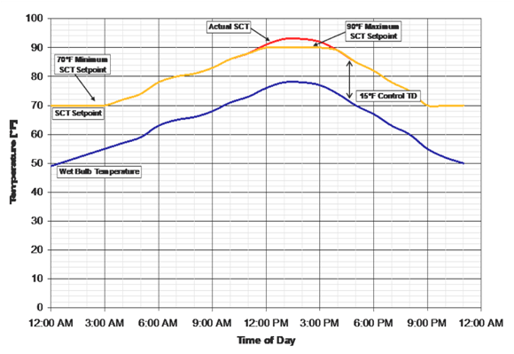
A new
supermarket with an evaporative condenser is being commissioned. The control
system designer has used a wetbulb-following control strategy to reset the
system saturated condensing temperature (SCT) setpoint. The refrigeration
engineer has calculated that adding a TD of 15°F (8.3°C) above the ambient
wetbulb temperature should provide a saturated condensing temperature setpoint
that minimizes the combined compressor and condenser fan power usage throughout
the year. What might the system SCT and SCT setpoint trends look like over an
example day?
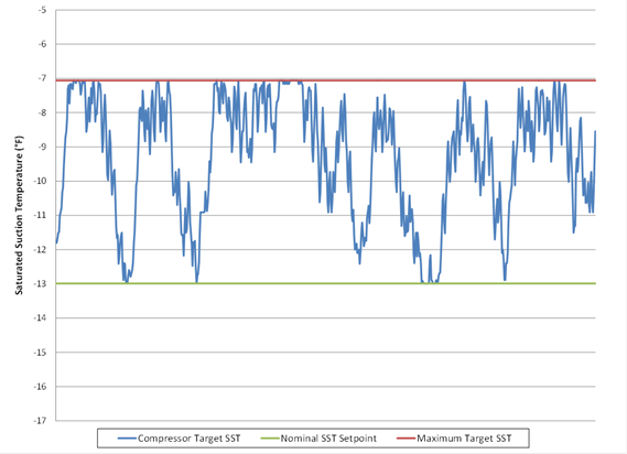
Answer
The following
figure illustrates what the actual saturated condensing temperature and SCT
setpoints could be over an example day using the wetbulb-following control
strategy with a 15°F (8.3°C) TD and also observing the 70°F (21°C) minimum
condensing temperature requirement. As the figure shows, the SCT setpoint is
continuously reset to 15°F (8.3°C) above the ambient wetbulb temperature until
the minimum SCT setpoint of 70°F is reached. The figure also shows a maximum SCT
setpoint (in this example, 90°F (32.2°C), which may be used to limit the maximum
control setpoint, regardless of the ambient temperature value or TD
parameter.
10.5.2.2 Condenser Specific
Efficiency
All newly installed evaporative
condensers, air-cooled condensers, and adiabatic condensers with capacities
greater than 150,000 Btuh (at the specific efficiency rating conditions) shall
meet the minimum specific efficiency requirements shown in Table 10-2.
Table 10-2: Fan-Powered Condensers – Minimum Specific Efficiency
Requirements
|
Condenser Type |
Minimum Specific
Efficiency |
Rating
Condition |
|
Evaporative-Cooled |
160 Btuh/Watt |
100°F Saturated Condensing Temperature (SCT), 70°F
Entering Wetbulb Temperature |
|
Air-Cooled |
65 Btuh/Watt |
105°F Saturated Condensing Temperature (SCT), 95°F
Entering Drybulb Temperature |
|
Adiabatic Dry Mode |
45 Btuh/Watt (Halocarbon) |
105°F Saturated Condensing Temperature (SCT), 95°F
Entering Drybulb Temperature |
Condenser specific
efficiency is defined as:
Condenser Specific Efficiency =
Total Heat Rejection (THR) Capacity/Input Power
The total heat rejection capacity
is defined at the rating conditions of 100°F SCT and 70°F outdoor wetbulb
temperature for evaporative condensers, and 105°F SCT and 95°F outdoor drybulb
temperature for air-cooled and adiabatic (halocarbon refrigerant only)
condensers. Total heat of rejection capacity for adiabatic condensers is
based on dry mode ratings (i.e. no precooling of the air). Input power is the
electric input power draw of the condenser fan motors (at full speed), plus the
electric input power of the spray pumps for evaporative condensers. The motor
power is the manufacturer’s published applied power for the subject equipment, which is
not necessarily equal to the motor nameplate rating. Power input for secondary
devices such as sump heaters shall not be included in the specific efficiency
calculation.
The data published in the condenser
manufacturer’s published rating for capacity and power shall be used to
calculate specific efficiency. For evaporative condensers, manufacturers
typically provide nominal condenser capacity and tables of correction factors
that are used to convert the nominal condenser capacity to the capacity at
various applied condensing temperatures and wetbulb temperatures. Usually the
manufacturer publishes two sets of correction factors: one is a set of “heat
rejection” capacity factors, while the other is a set of “evaporator ton”
capacity factors. Only the “heat rejection” capacity factors shall be used to
calculate the condenser capacity at the efficiency rating conditions for
determining compliance with this section.
For air-cooled and adiabatic
condensers, manufacturers typically provide the capacity at a given temperature
difference (TD) between SCT and drybulb temperature. Manufacturers typically
assume that air-cooled condenser capacity is linearly proportional to TD; the
catalog capacity at 20°F TD is typically twice as much as at 10°F TD. The
condenser capacity for air-cooled and adiabatic condensers at a TD of 10°F shall
be used to calculate efficiency. If the capacity at 10°F TD is not provided, the
capacity shall be scaled linearly.
Depending on the type of condenser,
the actual manufacturer’s rated motor power may vary from motor nameplate in
different ways. Air-cooled condensers with direct-drive original equipment
manufacturer (OEM) motors may use far greater input power than the nominal motor
horsepower would indicate. On the other hand, evaporative condenser fans may
have a degree of safety factor to allow for higher motor load in cold weather
conditions (vs. the 100°F SCT/70°F WBT specific efficiency rating conditions).
Thus, actual motor input power from the manufacturer must be used for
direct-drive air-cooled condensers. For evaporative condensers and fluid
coolers, the full load motor power, using the minimum allowable motor
efficiencies published in the Nonresidential Appendix NA-3: Fan Motor
Efficiencies, is generally conservative, but manufacturer’s applied power should
be used whenever possible to more accurately determine specific efficiency.
There are three exceptions to the
condenser specific efficiency requirements.
1.
If the store is located in Climate Zone 1 (the cool coastal region in
Northern California).
2.
If an existing condenser is reused for an addition or alteration.
3.
If the condenser capacity is less than 150,000 Btuh at the specific
efficiency rating conditions.
Example
10-13
Question
An
air-cooled condenser is being designed for a new supermarket. The refrigerant is
R-507. The condenser manufacturer’s catalogue states that the subject condenser
has a capacity of 500 MBH at 10°F TD between entering air and saturated
condensing temperatures with R-507 refrigerant. Elsewhere in the catalog, it
states that the condenser has 10 ½ hp fan motors that draw 450 Watts each. Does
this condenser meet the minimum efficiency requirements?
Answer
First,
the condenser capacity must be calculated at the specific efficiency rating
condition. From Table 10-6, we see that the rating conditions for an air-cooled
condenser are 95°F entering drybulb temperature and 105°F SCT. The catalog
capacity is at a 10°F temperature difference, which is deemed suitable for
calculating the specific efficiency (105°F SCT - 95°F entering drybulb = 10°F
TD). Input power is equal to the number of motors multiplied by the input power
per motor:
10
fan motors x 450 Watts = 4,500 Watts fan motor
The
specific efficiency of the condenser is therefore:
500MBH
x 1,000 Btu/hr / 4,500Watts = 111Btu/hr/Watts 4,500
Watts
This
condenser has a specific efficiency of 111 Btuh per watt, which is higher than
the 65 Btuh per watt minimum requirement. This condenser meets the minimum
specific efficiency requirements.
Example
10-14
Question
An
evaporative condenser is being designed for a new supermarket. The
manufacturer’s catalog provides a capacity of 2,000 MBH at standard conditions
of 105°F SCT and 78°F wetbulb temperature. The condenser manufacturer’s catalog
provides the following heat rejection capacity factors:
Elsewhere
in the catalog, it states that the condenser model has one 10 HP fan motor and one 2
HP pump motor. Fan motor efficiencies and motor loading factors are not provided
by the manufacturer. Does this condenser meet the minimum efficiency
requirements?
Answer
First,
the condenser capacity must be calculated at the specific efficiency rating
condition. From Table 10-6, we see that the rating conditions for an evaporative
condenser are 100°F SCT, 70°F WBT and a minimum specific efficiency requirement
is 160 Btuh/watt. From the Heat Rejection Capacity Factors table, we see that
the correction factor at 100°F SCT and 70°F WBT is 0.95. The capacity of this
model at the specific efficiency rating conditions is:
2,000
MBH/0.95 = 2,105 MBH
To
calculate input power, we will assume 100% fan and pump motor loading and
minimum motor efficiencies since the manufacturer has not yet published actual
motor specific efficiency at the specific efficiency rating conditions. We look
up the minimum motor efficiency from Nonresidential Appendix NA-3: Fan Motor
Efficiencies. For a 10 HP six-pole open fan motor, the minimum efficiency is
91.7%. For a 2 HP six-pole open pump motor, the minimum efficiency is 87.5%. The
fan motor input power is calculated to be:
1
Motor x 10 HP x 746 watts x 100% assumed loading = 8,135
watts
Motor
HP 91.7% efficiency
The
pump motor input power is calculated to be:
1
Motor x 2 HP x 746 watts x 100% assumed loading = 1,705
watts
Motor
HP 87.5% efficiency
The
combined input power is therefore:
8,135
watts + 1,705 watts = 9,840 watts
Note:
Actual motor power should be used when available. (See note in text.)
Finally,
the efficiency of the condenser is:
(2,105
MBH x 1,000 Btuh) / 9,840 watts = 214 Btuh/watt MBH
214
Btuh per watt is higher than the 160 Btuh per watt requirement; this condenser
meets the minimum efficiency requirements.
Example
10-15
Question
An
adiabatic condenser is being designed for a new supermarket. The refrigerant is
R-407A. The condenser manufacturer’s catalogue states that the subject condenser
has a capacity of 550 MBH at 10°F TD between entering air drybulb temperature
and saturated condensing temperatures with R-407A refrigerant when operating in
dry mode. Elsewhere in the catalog, it states that the condenser has two 5 hp
fan motors that draw 4.5 kW each. Does this condenser meet the minimum
efficiency requirements?
Answer
First,
the condenser capacity must be calculated at the specific efficiency rating
condition. From Table 10-6, we see that the rating conditions for an air-cooled
condenser are 95°F entering drybulb temperature and 105°F SCT. The catalog
capacity is rated at a 10°F temperature difference, which is deemed suitable for
calculating the specific efficiency (105°F SCT - 95°F entering drybulb = 10°F
TD). Input power is equal to the number of motors multiplied by the input power
per motor:
2
fan motors x 4500 Watts = 9,000 watts
The
specific efficiency of the condenser is therefore:
(550MBH
x 1,000 Btu/hr/MBH) / 9000 watts = 61 Btu/hr/watts
This
condenser has a specific efficiency of 61 Btuh per watt, which is higher than
the 45 Btuh per watt minimum requirement. This condenser meets the minimum
specific efficiency requirements.
10.5.2.3 Condenser Fin
Density
Air-cooled condensers shall
have a fin density no greater
than 10 fins per inch. Condensers with higher fin densities have a higher risk
of fouling with airborne debris. This requirement does not apply for air-cooled
condensers that use a microchannel heat exchange surface, since this type of
surface is not as susceptible to permanent fouling in the same manner as
traditional tube-and-fin condensers with tight fin spacing.
The fin spacing requirement does
not apply to condensers that are reused for an addition or alteration.
10.5.2.4 Adiabatic
Condenser Sizing
New adiabatic condensers on new
refrigeration systems must follow the condenser sizing, fan control, and
efficiency requirements as described in §120.6(b)1E.
Condensers must be sized to provide
sufficient heat rejection capacity under design conditions while
maintaining a specified maximum temperature difference between the refrigeration
system SCT and
ambient temperature. The design condenser capacity shall be greater than the
calculated combined total heat of rejection (THR) of the dedicated compressors that
are served by the condenser. If multiple condensers are specified, then the
combined capacity of the installed condensers shall be greater than the
calculated heat of rejection. When determining the design THR for this
requirement, reserve or backup compressors may be excluded from the
calculations.
§120.6(b)1E
provides maximum design SCT values for adiabatic condensers. For this section,
designers should use the 0.5 percent design drybulb temperature (DBT) from Table
10-4 – Design Day Data for California Cities in the Reference Joint
Appendices JA2 to demonstrate
compliance with this requirement.
Standard practice is for published
condenser ratings to assume the capacity of adiabatic condensers is proportional
to the temperature difference (TD) between SCT and DBT for operation in dry
mode, regardless of the actual ambient temperature entering the condenser. For
example, the capacity of an adiabatic condenser operating at an SCT of 80°F with
a DBT of 70°F is assumed to be equal to the same unit operating at 110°F SCT and
100°F DBT during dry mode operation, since the TD across the condenser is 10°F
in both examples. Thus, similar to air-cooled condensers, the requirement for
adiabatic condensers does not have varying sizing requirements for different
design ambient temperatures.
However, the Energy Standards have
different requirements for adiabatic condensers depending on the space
temperatures served by the refrigeration system. The maximum design SCT
requirements are listed in Table
10-5 below:
|
Refrigerated
Load Type |
Space
Temperature |
Maximum SCT
(dry mode) |
|
Cooler
|
≥ 28°F |
Design DBT plus
30°F |
|
Freezer
|
<
28°F |
Design DBT plus
20°F |
Often, a single refrigeration
system and the associated condenser will serve a mix of cooler and freezer load.
In this instance, the maximum design SCT shall be a weighted average of the
requirements for cooler and freezer loads, based on the design evaporator
capacity of the spaces served.
Example
10-16
Question
An
adiabatic condenser is being sized for a system that has half of the installed
capacity serving cooler space and the other half serving freezer space. What is
the design TD to be added to the design drybulb temperature?
Answer
Using
adiabatic condensers for coolers has a design approach of 30°F and for freezers
a design approach of 20°F. When a system serves freezer and cooler spaces, a
weighted average should be used based on the installed capacity. To calculate
the weighted average, multiply the percentage of the total installed capacity
dedicated to coolers by 30°F. Next, multiply the percentage of the total
installed capacity dedicated to freezers by 20°F. The sum of the two results is
the design condensing temperature approach. In this example, the installed
capacity is evenly split between freezer and cooler space. As a result, the
design approach for the air-cooled condenser is 25°F.
(50%
x 20 °F) + (50% x 30°F) = 10 °F + 15 °F = 25 °F
This section addresses mandatory
requirements for remote compressor systems and condensing units used for
refrigeration. In addition to the requirements described below, all the
compressors and all associated components must be designed to operate at a
minimum condensing temperature of 70°F (21°C) or less.
10.5.3.1 Floating Suction
Pressure Controls
Compressors and multiple-compressor
suction groups must have floating suction pressure control to reset the
saturated suction pressure control setpoint based on the temperature
requirements of the attached refrigeration display cases or walk-ins.
Exceptions to the floating suction
pressure requirements are:
1.
Single compressor systems that do not have continuously variable-capacity
capability.
2.
Suction groups that have a design saturated suction temperature of 30°F or
higher.
3.
Suction groups that comprise the high side of a two-stage or cascade system.
4.
Suction groups that primarily serve chillers for secondary cooling fluids.
5.
Existing compressor systems that are reused for an addition or alteration.
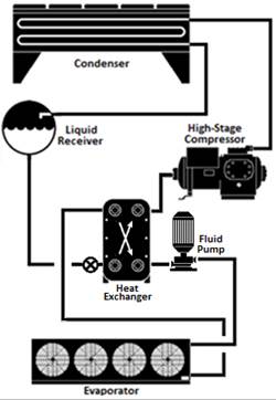
The examples of a two-stage system
and a cascade system are shown in Figure 10-7 and Figure 10-8, respectively.
Figure 10-9 shows a secondary fluid system.
Figure 10-7: Two-Stage System Using a Two-Stage
Compressor
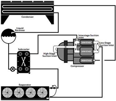
Figure 10-8:
Cascade System
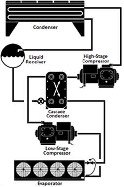
Figure 10-9:
Secondary Fluid System
Example 10-16
Question
A retail food
store has four suction groups, A, B1, B2, and C, with design saturated suction
temperatures (SST) of -22°F, -13°F, 28°F and 35°F, respectively. System A is a
condensing unit. The compressor in the condensing unit is equipped with two
unloaders. Suction group B1 consists of a single compressor with no
variable-capacity capability. Suction group B2 has four compressors with no
variable-capacity capability and suction group C has three compressors with no
variable-capacity capability. Which of these suction groups are required to have
floating suction pressure control?
Answer
Suction
groups A and B2 are required to have floating suction pressure control. The
rationale is explained below.
Suction group
A: Although the suction group has only one compressor, the compressor has
variable-capacity capability in the form of unloaders. Therefore, the suction
group is required to have floating suction pressure control.
Suction group
B1: The suction group has only one compressor with no variable-capacity
capability. Therefore, the suction group is not required to have floating
suction pressure control.
Suction group
B2: Although the suction group has compressors with no variable-capacity
capability, the suction group has multiple compressors that can be sequenced to
provide variable-capacity capability. Therefore, the suction group is required
to have floating suction pressure control.
Suction group
C: The design SST of the suction group is higher than 30°F. Therefore, the
suction group is not required to have floating suction pressure
control.
Example
10-17
Question
A retail food
store has two suction groups, a low-temperature suction group A (-22°F design
SST) and medium-temperature suction group B (18°F design SST). Suction group A
consists of three compressors. Suction group B has four compressors that serve a
glycol chiller working at 23°F. Which of these suction groups are required to
have floating suction pressure control?
Answer
Suction group
A: The suction group has multiple compressors. Therefore, the suction group is
required to have floating suction pressure control.
Suction group
B: Although the suction group has multiple compressors, it serves a chiller for
secondary cooling fluid (glycol). Therefore, the suction group is not required
to have floating suction pressure control.
Example
10-18
Question
A retail food
store is undergoing an expansion and has two refrigeration systems: an existing
system and a new CO2 cascade system. The existing system consists of
four compressors and a design SST of 18°F. The cascade refrigeration
system consists of four low-temperature compressors operating at -20°F SST
and three medium-temperature compressors operating at 26°F SST. Which of these
systems are required to have floating suction pressure control?
Answer
Existing
system: Although the system has multiple compressors, the compressor system is
being reused, and the existing rack controller and sensors may not support
floating suction pressure control. Therefore, the system is not required to have
floating suction pressure control.
Cascade
system: Only the low-temperature suction group of the system is required to have
floating suction pressure control.
Evaporator coils are sized to
maintain a design fixture temperature under design load conditions. Design loads
are high enough to cover the highest expected load throughout the year and
inherently include safety factors. The actual load on evaporator coils varies
throughout the day, month, and year, and an evaporator coil operating at the
design saturated evaporating temperature (SET) has excess capacity at most
times. The SET can be safely raised during these times, reducing evaporator
capacity and reducing the required “lift” of the suction group, saving energy at
the compressor while maintaining proper fixture (and product) temperature.
In a floating suction pressure
control strategy, the suction group target saturated suction temperature (SST)
setpoint is allowed to vary depending on the actual requirements of the attached
loads, rather than fixing the SST setpoint low enough to satisfy the highest
expected yearly load. The target setpoint is adjusted so that it is just low
enough to satisfy the lowest current SET requirement of any attached
refrigeration load while maintaining target fixture temperatures, but not any
higher. The controls are typically bound by low and high setpoint limits. The
maximum float value should be established by the system designer, but a minimum
value equal to the design SST (that is no negative float) and a positive float
range of 4-6°F of saturation pressure equivalent have been used
successfully.
Figure 10-10 shows hourly values
for floating suction pressure control over one week, expressed in equivalent
saturation temperature. The suction pressure control setpoint is adjusted to
meet the temperature setpoint at the most demanding fixture or walk-in. The
difference in SST between the floating suction pressure control and fixed suction pressure
control translates into reduced compressor work and, thus, energy savings for
the floating suction control.
Figure 10-10:
Example of Floating Suction Pressure Control
A.
Floating Suction Pressure Control With
Mechanical Evaporator Pressure Regulators
Mechanical evaporator pressure
regulators (EPR valves) are often used on multiplex systems to maintain
temperature by regulating the SET at each evaporator connected to the common
suction group, and often to function as a suction stop valve during defrost. EPR
valves throttle to maintain the pressure at the valve inlet and, thus,
indirectly control the temperature at the case or walk-in. The valves are
manually adjusted to the pressure necessary to provide the desired fixture or
walk-in air temperature. The load (circuit) with the lowest EPR pressure governs
the required compressor suction pressure setpoint.
Floating suction pressure on a
system with EPR valves requires special attention to valve settings on the
circuit(s) used for floating suction pressure control. EPR valves on these
circuit(s) must be adjusted “out of range,” meaning the EPR pressure must be set
lower than what would otherwise be used to maintain temperature. This keeps the
EPR valve from interfering with the floating suction control logic. In some
control systems, two circuits are used to govern floating suction control,
commonly designated as primary and secondary float circuits. EPR valves may also
be equipped with electrically controlled wide-open solenoid pilots for more
fully automatic
control, if desired.
Similar logic is applied on systems
using on/off liquid
line solenoid valves (LLSV) for temperature control, with the control of the
solenoid adjusted slightly out of range to avoid interference with floating
suction pressure.
These procedures have been employed
to float suction on supermarket control systems since the mid-1980’s; however
careful attention is still required during design, start-up, and commissioning
to insure control is effectively coordinated.
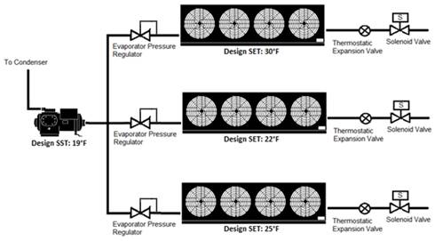
Figure 10-11:
Evaporators With Evaporative Pressure Regulator Valves
B.
Floating Suction Pressure Control With
Electronic Suction Regulators
An electronic suction regulator
(ESR) valve is an electronically controlled valve used in place of a mechanical
evaporator pressure regulator valve. ESRs are also known in the industry as
electronic evaporator pressure regulators (EEPRs). ESR valves are not pressure
regulators; instead they control the flow through the evaporator based on a
setpoint air temperature at the case or walk-in. ESR valves are modulated to
maintain precise temperature. This modulation provides more accurate temperature
compared to an EPR that controls temperature indirectly through pressure and is
subject to pressure drop in piping and heat load (and thus TD) on the evaporator
coil.
Floating suction pressure
strategies with ESR valves vary depending on the controls manufacturer but will
generally allow for more flexibility than systems with EPR valves. In general,
the control system monitors how much each ESR valve is opened. If an ESR is
fully open, indicating that the evaporator connected to the ESR requires more
capacity, the control system will respond by decrementing the SST setpoint. If
all ESR valves are less than fully open, the control system increments the
suction pressure up until an ESR valve fully opens. At this point, the control
system starts floating down the suction pressure again. This allows suction
pressure to be no lower than necessary for the most demanding fixture.
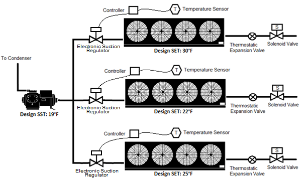
Figure 10-12 shows multiple
evaporators controlled by ESR valves connected to a common suction group.
Figure 10-12: DX
Evaporators With ESRs on a Multiplex System
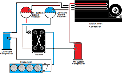
10.5.3.2 Liquid
Subcooling
Liquid subcooling must be provided
for all low-temperature compressor systems with a design cooling capacity of
100,000 Btuh or greater and with a design saturated suction temperature of -10°F
or lower. The subcooled liquid temperature of 50°F or less must be maintained
continuously at the exit of the subcooler. Subcooling load may be handled by
compressor economizer ports or by using a suction group operating at a saturated
suction temperature of 18°F or higher. Figure 10-13 and Figure 10-14 show
example subcooling configurations.
Exceptions to the liquid subcooling
requirements are:
1.
Low-temperature cascade systems that condense into another refrigeration system rather than
condensing to ambient temperature.
2.
Existing compressor systems that are reused for an addition or alteration.
Figure 10-13:
Liquid Subcooling Provided by Scroll Compressor Economizer Ports
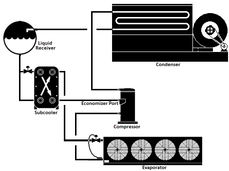
Figure 10-14: Liquid
Subcooling Provided By a Separate Medium-Temperature System
All lighting for refrigerated display
cases, and glass doors of walk-in coolers and freezers shall be controlled by
either automatic
time switch controls or motion sensor controls or both.
A.
Automatic Time Switch Control
Automatic time switch controls
shall turn off the lights during nonbusiness hours.
Timed overrides for a display case
lineup or walk-in case may be used to turn on the lights for stocking or
nonstandard business hours. The override must time-out and automatically turn
the lights off again in one hour or less. The override control may be enabled
manually (e.g. a push button input to the control system) or may be scheduled by the
lighting control or energy management system.
B.
Motion Sensor
Motion sensor control can be used
to meet this requirement by either dimming or turning off the display case
lights when space near the case is vacated. The lighting must dim so that the
lighting power reduces to 50% or less. The maximum time delay for the motion
sensor must be 30 minutes or less.
This section addresses mandatory
requirements for the use of heat recovery from refrigeration system(s) to HVAC system(s) for space heating
and the charge limitations when implementing heat recovery, including an
overview of configurations and design considerations for heat recovery systems.
Heat rejected from a refrigeration system is the total of the cooling load
taken from display cases and walk-ins in the store plus the electric energy used
by the refrigeration compressors. Consequently, there is a natural relationship
between the heat available and the heating needed; a store with greater
refrigeration loads needs more heat to makeup for the cases and walk-ins and has
more heat available.
The heat recovery requirements
apply only to space heating.
There are many possible heat
recovery design configurations due to the variety of refrigeration systems, HVAC
systems, and potential arrangement and locations of these systems. Several
examples are presented here, but the Energy Standards do not require these
configurations to be used. The heat recovery design must be consistent with the
other requirements in the Energy Standards, such as condenser floating head
pressure.
At least 25 percent of the sum of
the design total heat of rejection (THR) of all refrigeration systems with
individual design THR of 150,000 Btu/h or greater must be used for space heat recovery.
Exceptions to the above
requirements for heat recovery are:
1.
Stores located in Climate Zone 15, which is the area around Palm Springs,
California. Weather and climate data are available in Joint Appendix JA2
2.
The above requirements for heat recovery do not apply to the HVAC and
refrigeration systems that are reused for an addition or alteration.
The Energy Standards also limit the
increase in hydrofluorocarbon (HFC) refrigerant charge
associated with refrigeration heat recovery. The increase in HFC refrigerant
charge associated with refrigeration heat recovery equipment and piping must not be
greater than 0.35 lbs. per 1,000 Btuh of heat recovery heating capacity.
Example
10-19
Question
A
store has three new distributed refrigeration systems, A, B and C, with design
THR of 140,000 Btuh, 230,000 Btu/h and 410,000 Btuh, respectively. What is the
minimum required amount of refrigeration heat recovery?
Answer
Refrigeration
systems B and C have design THR of greater than 150,000 Btu/h, whereas
refrigeration system A has a design THR of less than 150,000 Btuh. Therefore,
the store must have the minimum refrigeration heat recovery equal to 25% of the
sum of THR of refrigeration systems B and C only. The minimum required heat
recovery is therefore:
25% x (230,000 Btuh + 410,000 Btuh) =
160,000 Btuh
Example
10-20
Question
How
should the THR be calculated for the purpose of this section?
Answer
The
THR value is equal to the total compressor capacity plus the compressor heat of
compression.
Example
10-21
Question
A
35,000 ft2 food store is expanding to add 20,000 square feet area.
The store refrigeration designer plans to use two existing refrigeration systems
with 600,000 Btu/h of design total heat rejection capacity and add a new
refrigeration system with a design total heat rejection capacity of 320,000
Btu/h. The store mechanical engineer plans to replace all the existing HVAC
units. Is the store required to have refrigeration heat recovery for space
heating?
Answer
Yes.
The store must have the minimum required refrigeration heat recovery from the
new refrigeration system. The new refrigeration system has a design THR of
greater than 150,000 Btu/h threshold. The minimum amount of the refrigeration
heat recovery is 25% of the new system THR. The existing refrigeration systems
are not required to have the refrigeration heat recovery.
10.5.5.1 Refrigeration Heat
Recovery Design Configurations
The
designer of heat recovery systems must consider the arrangement of piping,
valves, coils, and heat exchangers as applicable to comply with the Energy Standards. Numerous
refrigeration heat recovery systems configurations are possible depending upon
the refrigeration system type, HVAC system type and the store size. Some possible
configurations are:
1.
Direct heat recovery.
2.
Indirect heat recovery.
3.
Water loop heat
pump system.
These
configurations are described in more detail with the following sections.
A.
Direct Heat Recovery
Figure 10-15 shows a
series-connected direct condensing heat recovery configuration. In this
configuration, the heat recovery coil is placed directly within the HVAC unit
airstream (generally the unit serving the main sales area), and the discharge
refrigerant vapor from the compressors is routed through the recovery coil and
then to the outdoor refrigerant condenser when in heating mode. If two or more refrigeration
systems are used for heat recovery, a multicircuit heat recovery coil could be
used.
This configuration is very suitable
when the compressor racks are close to the air handling units used for heat
recovery. If the distance is too far, an alternative design should be
considered; the long piping runs may result in a refrigerant charge increase
that exceeds the maximum defined in the Energy Standards, or there may be
excessive pressure losses in the piping that could negatively affect compressor
energy.
Figure 10-15: Series Direct Heat Recovery
Configuration
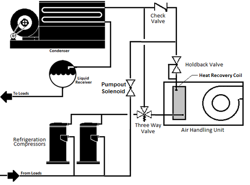
Figure 10-16 shows a
parallel-connected direct-condensing configuration. In this configuration, the
heat recovery coil handles the entire condensing load for the connected
refrigeration system(s) when the air-handling unit is in heating mode. Reduced
refrigerant charge is the primary advantage of this configuration. Since the
unused condenser (either the heat recovery condenser or the outdoor condenser)
can be pumped out, there is no increase in refrigerant charge. A high degree of
design expertise is required with this configuration in that the heat recovery
condenser and associated HVAC system must take the entire heating load while
operating at reasonable condensing temperatures—in any event, no higher than the
system design SCT and in most instances with reasonable design no higher than
95°F-100°F condensing temperature in the heat recovery condenser. Ducting with
under case or low return air design is essential in this type of system, to
obtain cooler
entering air and maintain reasonable condensing temperatures. Provision is
required for practical factors such as dirty air filters.
Since the main condenser is not in
use during heat recovery, the condenser floating head pressure requirements do
not apply.
Figure 10-16 Parallel Direct Condensing Heat Recovery
Configuration
B.
Indirect Heat Recovery
Figure 10-17 shows an indirect heat
recovery configuration with a fluid loop. In this configuration, the recovered
heat is transferred from the refrigerant to an intermediate fluid, normally
water or water-glycol, which is circulated through a fluid-to-air heat exchanger
located in the air-handling unit airstream. Like the direct condensing
configuration, discharge refrigerant gas from the compressors is routed through
the refrigerant-to-fluid heat exchanger and then to the outdoor refrigerant
condenser when in heating mode.
The refrigerant-to-fluid heat
exchanger can be located close to the refrigeration system compressors,
maximizing the available heat for recovery while keeping the overall refrigerant
charge increase low. This configuration is also suitable when multiple HVAC
units are employed for the refrigeration heat recovery. Indirect systems must
use a circulation pump to circulate the fluid between the HVAC unit and the
recovery heat exchanger.
Figure
10-17: Indirect Heat Recovery With an Indirect Loop
Multiple refrigeration systems can
also be connected in parallel or in series, using a common indirect fluid loop.
Figure 10-18 shows three refrigeration systems connected in series by a common
fluid loop. The temperatures shown are only examples.
Figure 10-18:
Series-Piped Indirect Water Recovery
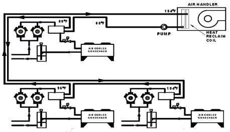
This configuration allows the
refrigerant-to-water condenser temperature difference (TD) to be kept low at
each refrigeration system (e.g. 8°-10°F is possible) while maintaining a
sufficiently high water-side TD at the air-handling unit (e.g. 20°-25°F
depending on specifics) to allow an effective selection of the water-to-air
heating coil vs. the available airflow. This method also minimizes both the
required fluid flow and pump power.
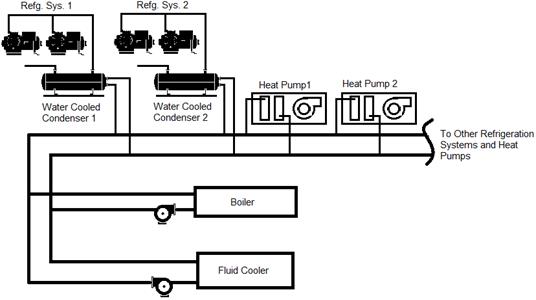
C.
Water Loop Heat Pump Heat Recovery
Water-source heat pumps (WLHP) can
be used for in conjunction with water cooled refrigeration systems, connected to
a common water loop as shown in Figure 10-19. Refrigeration systems heat pumps
serving various zones of the store reject heat into a water loop, which in turn
is rejected to ambient by an evaporative fluid cooler. When the heat pumps
are in heating mode, they extract the heat rejected by the refrigeration systems
from the water loop. Additional heat, if required, is provided by a boiler
connected to the water loop. A significant advantage of this design is low
refrigerant charge, since the refrigeration systems use a compact water-cooled
condenser, typically with less charge than an air-cooled condenser and no heat
recovery condenser is required. Compared with other methods, however, the
electric penalty is somewhat higher to utilize the available heat.
The floating pressure requirements
in the standard would apply to the fluid coolers, i.e. controls to allow
refrigeration systems to float to 70°F SCT and use of wetbulb following control
logic.
Figure 10-19: Water
Loop Heat Pump Example
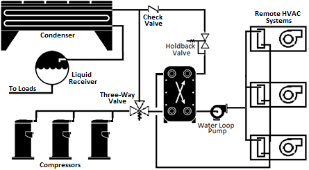
10.5.5.2 Control
Considerations
A.
Holdback Considerations
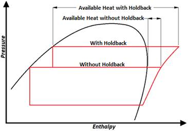
For direct and indirect systems, a
holdback valve is required to control the refrigerant condensing temperature in
the heat recovery coil (for direct systems) or the refrigerant-to-water condenser (for
indirect systems) during heat recovery. Regulating the refrigerant pressure to
achieve condensing recovers the latent heat from the refrigerant. Without
condensing, only the sensible heat (i.e. superheat) is obtained, which is only a
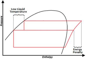
small fraction of the available heat. Figure 10-20 is a pressure-enthalpy
diagram showing the difference in available recovery heat from a refrigeration
system with and
without a holdback valve.
Figure 10-20:
Pressure-Enthalpy Diagram With and Without a Holdback Valve
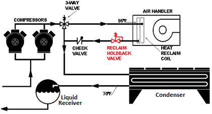
The holdback valve regulates
pressure at the inlet and is at the exit of the recovery heat exchanger. Figure
10-21 shows a direct-condensing configuration with the proper location of the
holdback valve.
Figure 10-21: Direct-Condensing Configuration Showing Location of
Holdback Valve
A more advanced design uses an electronic holdback valve
controlled based on the temperature of the air entering the heat recovery coil.
The electronic heat recovery holdback valve controls the valve inlet pressure
and thus the heat recovery coil condensing temperature to maintain only the
pressure necessary to achieve the required condensing TD (heat recovery SCT less
entering air temperature), thereby minimizing compressor efficiency penalty.
This is particularly useful when the volume outside air can significantly
change the mixed air temperature entering the heat recovery coil. In colder
climates, reducing the heat recovery holdback pressure can be important as a
means to avoid over-condensing (i.e. subcooling). As shown in the
pressure-enthalpy diagram above, there is additional flash gas handled by the
condenser (even if the refrigerant fully condenses in the heat recovery coil),
which is necessary to maintain piping and condenser velocity and, thus, minimize
the charge in the outdoor condenser.
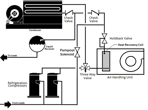
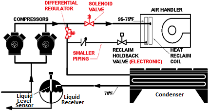
Other designs can replace the three-way valve with a
differential pressure regulator and solenoid valve. Figure 10-22 shows a
direct-condensing configuration with an electronic heat recovery holdback valve,
solenoid valve, and differential pressure regulator.
Figure 10-22:
Direct-Condensing Configuration Showing Differential Regulator,
Solenoid
Valve, Electronic Holdback Valve
B.
Heat Recovery and Floating Head Pressure
There is typically a tradeoff
between heat recovery and refrigeration system efficiency, in that compressor
discharge pressure must be increased to provide condensing for heat recovery. If
implemented properly, the electric penalty at the refrigeration system
compressors is small compared to the heating energy savings.
The Energy Standards require that the minimum
condensing temperature at the refrigeration condenser shall be 70°F or less.
That means that (in the typical case of series-connected heat recovery) the
refrigeration “cycle” still benefits from lower refrigerant liquid temperature,
even if the compressor power is somewhat increased during heat recovery. The
pressure-enthalpy diagram shown in Figure 10- 23 shows the incremental energy
penalty at the refrigeration compressors due to the higher discharge pressure
required for heat recovery, as well as the lower liquid temperature (and thus
improved refrigerant cooling capacity) by floating head pressure at the outdoor
condenser.
Figure 10-23:
Pressure-Enthalpy Diagram for Heat Recovery
10.5.5.3 Recovery Coil
Design Considerations
A.
Recovery Coil Sizing Example
Selecting an appropriately sized
heat recovery coil is essential to proper heat recovery system operation. The following example
details the process of selecting a right-sized heat recovery coil.
Example
10-22
Question
A
supermarket is being constructed that will use heat recovery. The refrigeration
system selected for recovery has the following parameters:
Design
refrigeration load: 455.8 MBH
System
design SST: 24°F
Representative
compressor capacity at design conditions: 54.2 MBH
Representative
compressor power at design conditions: 5.59 kW
The
HVAC system
serving the supermarket sales area is a central air-handling unit. Heat recovery
will be accomplished with a direct-condensing recovery coil inside the
air-handling unit, downstream of both the return air duct and the outside air
damper. The air-handling unit has the following design parameters:
Design
air volume: 25,000 cfm
Design
coil face area: 41.7 ft2
To
avoid excessive pressure drop across the recovery coil, the designer will select
a coil with a fin density of 10 fins
per inch. The heat recovery circuit will use a holdback valve set at 95°F
SCT.
What
is the procedure for selecting a heat recovery coil?
Answer
To
size a heat recovery system, the designer should first establish a design
recovery coil capacity by analyzing the refrigeration system from which heat
will be recovered. Best practice dictates that the recovery system should be
sized to recover most of the available system total heat of rejection
at typical operating conditions, not peak conditions. Since we are designing for
average operating conditions, the designer assumes the average refrigeration
load is 70% of the design load. Therefore, the average system THR for heating
design is:
Average
System THR = 70% x Design Refrigeration Load x THR Adjustment
Factor
where:
THR
Adjustments Factor = Representative Compressor
THR
Representative Compressor Capacity
and:
Rep.
Compressor THR = Rep. Compressor Capacity + Rep. Compressor Heat of
Compression
Using
values from the example:
Representative Compressor THR = 54.2MBH +
(5.50 kW x 3.415
MBH)
kW
Representative Compressor THR = 73.3 MBH
Therefore,
THR
Adjustment Factor = 73.3
MBH
54.2 MBH
THR Adjustment Factor = 1.35
Using
the values in this example and the calculated THR adjustment factor, the average
system THR is:
Average
system THR = 70% x 455.8 MBH x1.35
Average
system THR = 430.1 MBH
The
recovery system will not be capable of extracting 100% of the total heat of
rejection since the condenser operates at a lower pressure and will reject
additional heat, even if the heat recovery coil achieves full condensing. In addition, the heat
recovery coil performance may often be limited by the available airflow across
the coil and the consequent temperature rise vs. the heat being transferred.
This performance is determined through evaluation of coil performance,
considering entering air temperature, and condensing temperature, as well as the
coil design (e.g. rows, fins, air velocity and other factors). Airside pressure
drop can be minimized by using a larger face area, requiring lower face velocity
and fewer rows.
For
in this example, it was assumed that after evaluating coil performance, 85% of
the average THR could be recovered with a reasonable coil velocity and coil
depth.
Available
Heat for Reclaim = 85% x Average System THR
Available
Heat for Reclaim = 85% x 430.1 MBH
Available
heat for Reclaim = 365.6 MBH
The
available heat for recovery is the design capacity of the recovery coil we will
select for our air-handling unit.
Next,
the designer needs to know the face velocity of the airstream in the
air-handling unit. The face velocity is:
F.V.
= Design cfm
AHU Face Area
F.V.
= 25,000
cfm
41.7 ft2
F.V.
= 600 ft/min
Finally,
the designer needs to know the temperature difference between the condensing
temperature (inside the recovery coil) and the temperature of the air entering
the recovery coil. Since the coil will be installed in an air-handling unit
downstream of the outside air damper, the designer assumes that the air entering
the coil is a mix of return air from the store and outside air. The designer
must determine an appropriate design temperature for the air entering the
recovery coil (entering air temperature or EAT) during average heating hours,
which in this instance was determined to be 65°F. From the example, the heat
recovery system will have a holdback valve setting of 95°F SCT. Therefore, the
temperature difference is:
TD
= SCT – EAT
TD
= 95oF - 65 oF
TD
= 30 oF
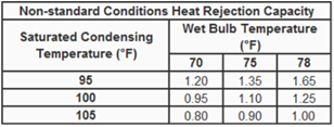
Using
the face velocity, design coil capacity, and temperature difference between
condensing temperature and entering air temperature, the designer then refers to
the air-handling unit catalog to select a recovery coil. Then the designer uses
the following two tables:
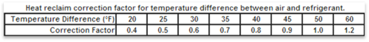
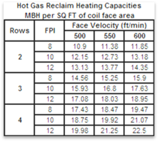
The
designer enters the first table with the calculated TD of 30°F, finding a
correction factor of 0.6. We enter the second table with the value:
MBH
per SQ FT = (Design Coil Capacity) / Correction
Factor
Coil Face Area
MBH
per SQ FT = (4184 MBH) /
0.6
41.7 ft2
MBH
per SQ FT = 16.72
Per
design requirements, the designer will select a 10-fin-per-inch coil. From the
second table, the designer selects the three-row, 10-fin-per-inch coil for this
application.
More
commonly, computerized selection tools are used to select heat recovery coils,
allowing vendors to provide multiple selections for comparison.
B.
Air-Side Integration Considerations
1.
Return Air Location
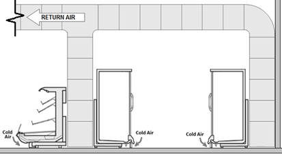
In supermarkets, ducting return air
from behind display cases or near the floor is beneficial in improving comfort
by removing the stagnant cool air that naturally occurs due to product
refrigeration cases. This approach also increases the effectiveness of
refrigeration heat recovery by increasing the temperature difference between the
return air temperature and the refrigerant condensing temperature in the heat
recovery coil. Figure 10-24 shows the location of an HVAC return air duct
positioned to scavenge cool air from the floor level near refrigerated display
cases.
Figure 10-24: Low Return Air Example
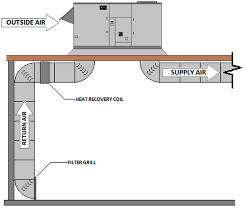
2.
Return Air Duct Configuration
Heat recovery can be incorporated
into rooftop HVAC units (RTU) by installing the heat recovery coil inside the
RTU cabinet or by installing in the return air duct upstream of the RTU, as
shown in Figure 10-25. Location inside the RTU is preferable when outside air is
a substantial part of the heating load, but location in the return air duct is
reasonable and can provide greater flexibility in selecting the heat recovery
coil (e.g. for low face velocity and pressure drop), particularly when coupled
with low return air on units in the refrigerated space, which
predominantly provide heating. The fan design must allow for the additional
ductwork and coil pressure drop.
Figure 10-25: Heat
Recovery Coil in Return Air Duct
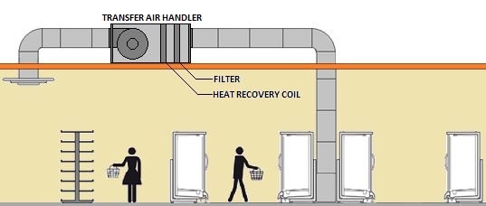
3.
Transfer Fan Configuration
A ducted transfer system is
sometimes employed to remove cold air from aisles with refrigerated display
cases (rather than blowing warm air into the refrigerated areas) and can be an
easy and appropriate way to use heat recovery, particularly from smaller
distributed systems. Figure 10-26 depicts a ducted transfer
system.
Figure 10-26: Ducted Transfer System
4.
Calculating Charge Increase
The Energy Standards require that the increase
in HFC refrigerant charge from all equipment related to heat recovery
for space heating shall be less than 0.35 lbs. for every 1,000 Btuh of heat
recovery capacity at design conditions. Refrigerant charge may increase due to
the addition of the recovery coil itself (either the refrigerant-to-air heat
exchanger for direct configurations, or the refrigerant-to-water heat exchanger
for indirect configurations) and the additional piping between the compressor
group and the recovery coil. In addition, the refrigerant leaving the recovery
coil and entering the refrigerant condenser will be mostly condensed, which
increases the charge in the outdoor condenser compared with normal operation.
Operating the outdoor condenser at lower pressure (i.e. the required floating
heat pressure control) vs. the higher setting at the heat recovery coil holdback
valve creates pressure drop, flashing of some liquid to vapor and an increase in
velocity due to the much larger volume of a pound of vapor vs. a point of liquid
refrigerant. Split condenser control, which is very common in cooler climates, can
also be used to close off and pump out half of the outdoor condenser.
It is the responsibility
of the system designer to fully understand how the heat recovery system affects
overall refrigerant charge.
Example
10-23
Question
A
heat recovery system is being designed for a new supermarket. The refrigerant is
R-404A. The proposed design is shown below:
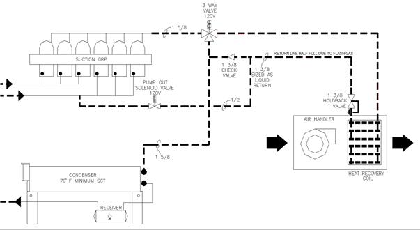
Which
piping runs should be included in the calculation of refrigerant charge increase
in the proposed design?
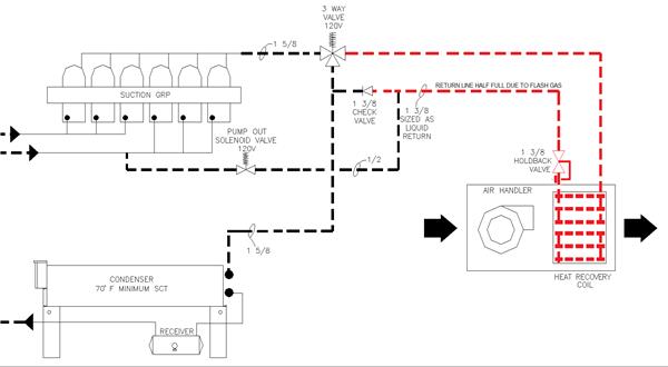
Answer
Only
the additional piping required to route the refrigerant to the heat recovery
coil needs to be considered in this calculation. The piping runs shown in red in
the following figure should be included in the calculation of refrigerant charge
increase from heat recovery.
Example
10-24
Question
What
is the refrigerant charge size increase in the example described above?
Answer
The
system designer prepares the following analysis to calculate the charge size in
the refrigerant piping.
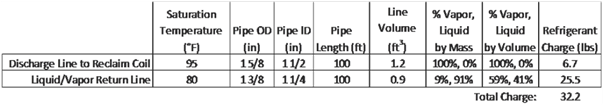
The
outdoor condenser has a capacity of 350 MBH at a TD of 10°F. Using the
manufacturer’s published data, the designer determines that the condenser normal
operating charge (without heat recovery) is 26.9 lbs. To calculate the charge
increase in the condenser due to heat reclaim, the designer estimates the
condenser could be as much as 75% full of liquid, resulting in a condenser
charge of 68.8 lbs. with heat recovery.
The
heat recovery coil has a capacity of 320 MBH at a design TD of 20°F. The system
designer uses manufacturer’s documentation to determine that the heat recovery
coil refrigerant charge is 14.1 lbs.
The
total refrigerant charge with heat recovery is:
32.2
lbs (piping) + 68.8 lbs (system condenser) + 14.1 lbs (recovery coil) = 115.1
lbs
Therefore,
the refrigerant charge increase with heat recovery is: 115.1 lbs – 26.9 lbs =
88.2 lbs
Example
10-25
Question
In
the example above, does the recovery design comply with the requirement in the
Energy Standards that the recovery design shall use at least 25% of the design
total heat of rejection (THR) of the refrigeration system?
Answer
The
system designer determines that the total THR of all the refrigeration systems
in the new supermarket is 800 MBH. From the previous example, the heat recovery
capacity is 320 MBH.
100
% x 320 MBH = 40%
800 MBH
Therefore,
the design complies with the Energy Standards.
Example
10-26
Question
In
the example above, does the recovery design comply with the requirement in the
Energy Standards that the recovery design shall not increase the refrigerant
charge size by more than 0.35 lbs. of refrigerant per 1,000 Btuh of recovery
capacity?
Answer
From
the previous example, the recovery capacity is 320 MBH at design conditions, and
the total refrigerant charge size increase is 88.2 lbs.
88.2
lbs = 0.28 lbs/Btuh
320 MBH
Since
the refrigerant charge increases by less than 0.35 lbs/MBH, this design complies
with the Energy Standards.
The specific requirements for
additions and alterations for commercial refrigeration are included in §120.6(b).