The duct model builds on the procedure given by Palmiter (see Francisco and Palmiter, 2003), that uses a steady state heat exchanger effectiveness approach to get analytical expressions for instantaneous duct loss and system efficiencies. The duct model, developed for this program by Palmiter, makes use of many of the same fundamental steady state equations and approach, but given the considerable complexity of the multiple duct systems, does not do a simultaneous solution of all the equations which a generalized Francisco and Palmiter scheme may imply. Instead the approach takes advantage of the small time steps used in the code, and in effect decouples the systems from each other and the zone by basing all losses and other heat transfers occurring during the time step on the driving conditions of Tair and Tmrt known at the beginning of the time step, similar to how heat transfers are determined during mass temperature updates .
Other assumptions made in the duct program: mass and thermal siphon effects in the duct system are ignored.
The duct system performance is analyzed at every time step. The duct air temperatures are calculated assuming they are operating at steady state, in equilibrium with the thermal conditions at the beginning of the time-step in the attic. Heat capacity effects of the ducts are ignored.
During each time step, the following steps are taken to find the duct system operating conditions such as the air temperatures in each duct, the losses, the heating or cooling delivered, etc.
Initially, for each time step, the duct systems performance is determined when operating at full capacity, independent of the load. The procedure starts at the return registers in each conditioned zone, where the duct air temperatures are the current timesteps conditioned zone air temperatures. The conditioned zone air entering the return register heats or cools, or both, as it traversed through each component of the duct system: the return duct, the return plenum, the heating/cooling device, and the supply ducts. That is, the duct air temperature rises or drops immediately downstream of the return register (where returns leaks are assigned to occur) due to mixing of leakage air at the air temperature in the unconditioned zone in which the return duct is located with the return air from the conditioned zone. It may also increase or decrease in temperature in the return plenum as it mixed with the air from the return duct in another unconditioned zone. After being heated or cooled by the air handler at its applicable heating/cooling capacity, it is then additionally heated or cooled by supply duct conductive gains/losses to the interior of the unconditioned zone.
Summing all the gains and losses in temperature of the duct
air as it travels through the system gives the supply temperature for the supply
duct, allowing the heat delivered at full capacity,
If the above useful heat delivered at full capacity is more than required by the load, then the equipment capacity is reduced to meet the load by assuming the system is only running the fraction Qload / Qdel of the time step. The needed capacity, Qneed is this fraction of the nominal capacity. The duct losses for the time step are also reduced by this fraction.
The above calculations are done each time step and the average Qneed summarized in the hourly output.
The above steps are presented in detail in the following sections, in the same sequence as described above.
In most cases in this section, the subscripted variables stand for arrays.
The subscript u stands for the unconditioned zone in which the duct is located.
The subscript c stands for conditioned zone number and its associated air handler system.
The subscript m stands for the mode of air handler operation: 0 off, 1 heating, 2 cooling.
The following data is input to model the duct/air handler system(s):
Duct inside areas
Asdc,u = supply duct inside area for air handler c in unconditioned zone u.
Ardc,u = return duct inside area for airhandler c in unconditioned zone u.
Duct insulation rated R values
Rsdc,u = supply duct rated R for air handler c in unconditioned zone u; hr-ft2-F/Btu.
Rrdc,u = return duct rated R for air handler c in unconditioned zone u; hr-ft2-F/Btu.
Inside duct area and inside area based resistance, and the outside duct area and outside area based resistance when there is a single duct segment in the return and supply branches
Consider one duct of constant inside diameter, di, and length L. The duct is insulated with insulation having a thermal conductivity k, and rated R value, Rrate. All R values herein are in the units of (hr-ft2-F/Btu).
Layed flat, the thickness the insulation layer is:
Equation 192
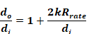
If the insulation is wrapped at this thickness around a duct of diameter di, the outside diameter, do, of the insulation will be:
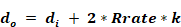
so,
Equation 193
Conduction heat transfer texts gives the overall conductance C of length L of an annular insulation layer as:
Equation 194

Dividing this by inside area, Ai=πdi L, gives the conductance per unit inside area:
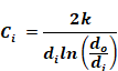
The duct resistance value per unit inside area is the reciprocal.
Equation 195
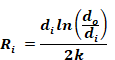
This can be written in terms of areas, and length L , as:
Equation 196
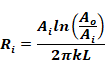
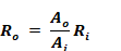
The duct resistance value based on outside area can be determined from Ri and Ai as:
Equation 197


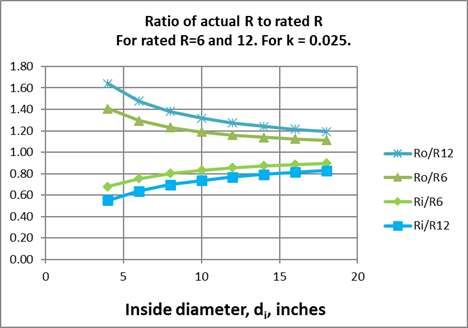
The R values of Equation 195 and Equation 197, divided by Rrated are plotted in Figure 25 as a function of the inside diameter of the duct branch.
Figure 25: Ratio of Actual R to Rated R
Duct system composed of multiple segments in the supply and return branches
Suppose the supply ducts from an air handler system are branched, with each branch having different sizes, lengths, rated insulation Rrate, and conductivity k values, and all the branches are in one unconditioned zone. These could be combined into one equivalent duct as follows.
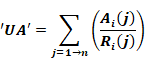
The duct branches, j=1à n, are combined, each of inside areas Ai(j), outside areas Ao(j), conductivities k(j), and inside area based resistances Ri(j). Using the method of Palmiter and Kruse (2003), the overall conductance of the branched duct system, based on inside area, is the sum of the conductances of each branch:
Equation 198
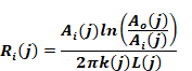
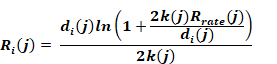
where Ri for each branch segment j is given by Equation 196 as
Equation 199
With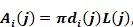
and using Equation 193, this can be written as
Equation 200
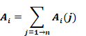
The total branch inside area is:
Equation 201
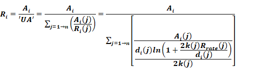
The effective overall resistance of the branched duct, based on inside area Ai, is thus:
Equation 202
The values of the terms needed for each branch segment, shown on the right hand side of Equation 202 are not available since the former ACM manual only requires that the following R is known:
Equation 203
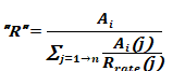
Equation 202 and Equation 203 would be equivalent if Equation 203 had the term Ri(j) in place of Rrate(j) As it is, Equation 203 gives the area weighted average Rrate, not Ri(j).
The total outside area is:
Equation 204
Based on outside area, the effective duct system resistance would be:
Equation 205
epssc,u = supply duct emissivity for air handler c in unconditioned zone u.
 = return
duct emissivity for air handler c in unconditioned zone u.
= return
duct emissivity for air handler c in unconditioned zone u.
Lsc,u = the fraction of the flow through the system c air handler fan that is leaked from the supply duct in unconditioned zone u. The leak is assigned to occur near the supply register so that the leakage air is at the supply register temperature.
Lrc,u = the fraction of the flow through the system c air handler fan that is leaked into the return duct in unconditioned zone u. The leak is assigned to occur at the return register. The air leaking into the duct is at the unconditioned zone temperature.
Flowm,c = the flow rate in cfm (at standard conditions) through the air handler for the cooling and heating modes, for of each system.
How much of the air handler flow of system c goes through each of its return and supply ducts is given by the per run input flow fractions:
Fmrc,u = fraction of flow of system c in the return duct located in unconditioned zone u.
Fmsc,u = fraction of flow of system c in the supply duct located in unconditioned zone u.
Fmrcc = fraction of flow of system c in the return duct located in conditioned zone c.
Fmrcc = fraction of flow of system c in the supply duct located in conditioned zone c.
For a given system c, the sum of the return duct fractions must add to one: Fmrc,1 + Fmrc,2 + Fmrc,3 = 1. Similarly for the supply duct fractions.
Following the procedure indicated in Section 2.10.1, the return duct air temperatures are determined first. Utilizing the heat exchanger effectiveness approach (see Mills (1992), and Appendix A), the temperature of the system c return duct air entering the return plenum from a return duct located in unconditioned zone number u is given by:

where Erm,c,u is the effectiveness of the return duct of system c in unconditioned zone u when operating in mode m:
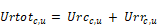
where Urtotc,u is the total conductance
between the return duct air and the equivalent surroundings temperature

Frdac,u is the fraction of return duct (dissolved surface node) conductance that goes to the Tairu node.
Frdrc,u is the fraction of the conductance from the c,u return duct air that goes to the Tmrtu radiant node.
The U terms are the conductances from the duct air to the mrt
and air nodes, determined as described in Appendix A. These conductance values,
and the similar supply duct values of Section 2.10.6 are used in the energy
balance of the unconditioned zone(s) containing ducts.
Urrcu = conductance from return duct air to Tmrt.
Urcc,u = conductance from return duct air to Tair.
The term Mcprm,c,u is the flow conductance (see below) for the return duct flow:

The total system flow, Mcpm,c is in the "flow conductance" form with the units Btu/hr-F:

where is the
volumetric heat capacity, which is taken as 1.08 Btu/(hr-F-cfm) for dry air at
the ASHRAE standard
conditions of density = 0.075 lbm/ft3 and cp
= 0.24 Btu/lbm-F.
is the
volumetric heat capacity, which is taken as 1.08 Btu/(hr-F-cfm) for dry air at
the ASHRAE standard
conditions of density = 0.075 lbm/ft3 and cp
= 0.24 Btu/lbm-F.
The term Tmixc,u is the mixed air just downstream of the return duct leakage, given by:

where Tempc is the temperature of conditioned zone c's air, assumed to be well-mixed.
The heat loss rate from the return duct via convection and radiation, needed in the unconditioned zone energy balance, is:

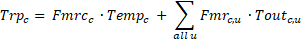
The final return plenum temperature of system c is found by summing the contributions to its plenum temperature from the return ducts in each unconditioned zone and the return ducts located in the conditioned zone. That is,
If the mode is heating or cooling, the temperature rise through the air handler heating or cooling equipment of system c at sensible capacity Capc is given by:
Equation 206
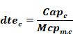
The program considers no heat losses or gains from the air handler components other than from the ducts.
The supply plenum temperature is given by:
Equation 207

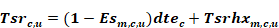
The supply register temperature for the supply duct of system c in unconditioned space u is:
Equation 208

where Esm,c,u is the effectiveness of the supply duct of system c in unconditioned zone u when operating in mode m:

Substituting the Tspc equation above into Equation 208 and rearranging gives:
Equation 209
where

Tsrhx is the temperature that would be delivered to the supply register with the current mode’s flow rate but with zero capacity such that dtec= 0. The duct system is then acting as a heat exchanger (thus the ‘hx’) between the connected conditioned and unconditioned zones.
The term sc,u , similar to Teqrc,u of Section 2.10.3, is an equivalent environmental temperature defined by

where
Usrc,u = conductance from supply duct air to Tmrt.
Uscc,u = conductance from supply duct air to Tair.
The supply duct flow rate is:

Given , Tsrc,u from above, the heat delivered to the conditioned zones by way of the supply ducts located in one or more of the unconditioned zones is given by summing the sensible heat delivered via each unconditioned zones:
Equation 210
Q delivered from ducts
=
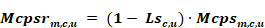
where Mcpsrm,c,u the flow out the supply register after the supply leakage is removed, is given by:
The heat delivered to the conditioned zones by way of ducts in the conditioned zone, which are assumed to have no losses or unbalanced leakage, is given by:
Equation 211
Q delivered directly
to conditioned zone 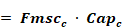
Adding the Q's of Equation 210 and Equation 211 gives the net heating (+), or cooling (-), delivered by the system c as:
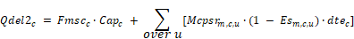
Qdelc = Fmscc∙Capc + ∑over u[Mcpsrm,c,u∙(Tsrc,u - Tempc)]
Substituting the expression for Tsrc,u from Equation 209 into this, Qdelc can be put in the form:
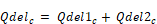
where Qdel1c is the part of Qdel that is independent of air handler capacity. That is, it is the Q delivered if dte is zero, and is the heat exchanged between the unconditioned and conditioned zones via the duct system:
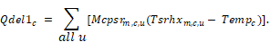
Qdel2c is the part of
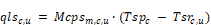
The rate of supply duct conduction losses this time step is given by:
If Qldc is smaller than the capacity Qdelc, then the system runs only part of the time step. In this case the run time fraction is:

The capacity required to meet the load is Qneedc:
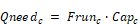
The duct conductive and leakage losses are also reduced by the same Frunc fraction.
In principle this won’t occur because the conditioned zone load is limited to the system capacity when it is calculated by the conditioned zone thermostat logic However, the capacity thus calculated is based on the duct efficiency [defined as η=Qload/Qneed] determined for the unconditioned zone during the last time-step, and as a result the load might exceed the capacity determined by the duct model efficiency this time-step.
That is, when the conditioned zone energy balance is performed, and for example heating is called for, then the output capacity of the heating system needs to be known, which requires knowing the duct system efficiency. But the duct efficiency is only known after the attic simulation is run.
To avoid iteration between the conditioned zone and attic zone modules, the most recent duct efficiency is used to determine the capacity in the conditioned zones thermostat calculations. When the attic simulation is next performed, if the conditioned zone was last running at capacity, and if the efficiency now calculated turns out to be higher than was assumed by the thermostat calculations, then the load will have exceeded the limiting capacity by a small amount depending on the assumed vs. actual efficiency. In cases like this, to avoid iteration, the limiting capacity is allowed to exceed the actual limit by a small amount, so that the correct air handler input energy demand is determined for the conditioned zone load allowed.
In this case, the system is set to run for the full sub-hour time step and the air handler meets the load by increasing its capacity with the following procedure. This procedure, a carryover from the 2008 Residential Building Standards ACM procedures, wherein no capacity limits were imposed on the air handler systems, is as follows.
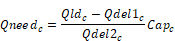
From the Qdel1 and Qdel2 equations it can be seen that the capacity needed in this case is:
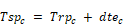
Thus, the temperature rise through the air handler needs to be:

The supply plenum temperature becomes:
The supply register temperatures is determined reusing Equation 208:

The supply duct losses now become:
The