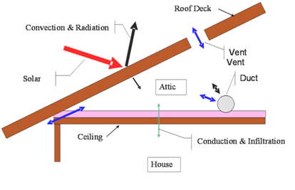
The compliance software models attics as a separate thermal zone and includes the interaction with the air distribution ducts, infiltration exchange between the attic and the house, the solar gains on the roof deck, and other factors. These interactions are illustrated in Figure 6.
2.6.1.1 Roof Rise
The roof rise is the ratio of rise to run (or pitch) and refers to the number of feet the roof rises vertically for every 12 feet horizontally. For roofs with multiple pitches, the roof rise that makes up the largest roof area is used.
2.6.1.2 Vent Area
This value is the vent area as a fraction of attic floor area. This value is not a compliance variable and is assumed set equal to attic floor area/300.
Figure 6: Attic Model Components
Source: California Energy Commission
2.6.1.3 Fraction High
The fraction of the vent area that is high due to the presence of ridge, roof, or gable end-mounted vents. Soffit vents are considered low ventilation. The default value is zero for attics with standard ventilation. Attics with radiant barriers are required to have a vent high fraction of at least 0.3.
2.6.1.4 Roof Deck/Surface Construction
Typical roof construction types are concrete or clay tile, metal tile, or wood shakes, or other steep- or low-sloped roofing types.
2.6.1.5 Solar Reflectance
This input is a fraction that specifies the certified aged reflectance of the roofing material or 0.1 default value for uncertified materials. The installed value must be equal to or higher than the value specified here. Roof construction with a roof membrane mass of at least 25 lbs/ft2 or a roof area that has integrated solar collectors is assumed to meet the minimum solar reflectance.
2.6.1.6 Thermal Emittance
Thermal emittance is the certified aged thermal emittance (or emissivity) of the roofing material, or a default value. Unless a default value is modeled, the installed value must be equal to or greater than the value modeled. The default value is 0.85 if certified aged thermal emittance value is not available from the Cool Roof Rating Council (www.coolroofs.org). Roof construction with a roof membrane mass of at least 25 lbs/ft2 or roof area incorporated integrated solar collectors is assumed to meet the minimal thermal emittance.
The conditioning is either ventilated or unventilated. Each characteristic of the roof is modeled to reflect the proposed construction. Values for solar reflectance and thermal emittance shall be default or from the Cool Roof Rating Council.
Roofs with solar collectors or with thermal mass over the roof membrane with a weight of at least 25 lbs/ft² may model the prescriptive values for solar reflectance and thermal emittance.
The standard design depends on the variables of the climate zone and roof slope. Low-sloped roofs (with a roof rise of 2 feet in 12 or less) in Climate Zones 13 and 15 will have a standard design aged solar reflectance of 0.63 and a thermal emittance of 0.85.
Steep-sloped roofs in Climate Zones 10-15 will have a standard design roof with an aged solar reflectance of 0.20 and a minimum thermal emittance of 0.85.
Roofs with solar collectors or with thermal mass over the roof membrane with a weight of at least 25 lbs/ft² are assumed to meet the standard design values for solar reflectance and thermal emittance.
A reflectance of 0.20 or higher is reported as a cool roof. A value higher than the default but less than 0.20 is reported as a non-standard roof reflectance value.
For each conditioned zone, the user enters the area and construction of each ceiling surface that is below an attic space. The compliance software shall allow a user to enter multiple ceiling constructions. Surfaces that tilt 60 degrees or more are treated as knee walls and are not included as ceilings. The sum of areas shall equal the overall ceiling area with conditioned space on the inside and unconditioned attic space on the other side.
The compliance software creates an attic zone with a floor area equal to the sum of the areas of all the user input ceilings below an attic in the building. The user specifies the framing and spacing, the materials of the frame path, and the R-value of the insulation path for each ceiling construction.
The user inputs the proposed insulation R-value rounded to the nearest whole R-value. For simulation, all ceiling below attic insulation is assumed to have nominal properties of R-2.6 per inch, a density of 0.5 lb/ft3, and a specific heat of 0.2 Btu/lb.
The standard design shall have the same area of ceiling below attic as the proposed design. The ceiling/framing construction is based on the prescriptive requirement and standard framing is assumed to be 2x4 wood trusses at 24 inches on center.
The area, insulation R-value, and layer of each construction are reported on the CF1R.
The roof pitch is the ratio of rise to run, (for example, 4:12 or 5:12). If the proposed design has more than one roof pitch, the pitch of the largest area is used.
The compliance software creates an attic zone roof. The roof area is calculated as the ceiling below attic area divided by the cosine of the roof slope where the roof slope is an angle in degrees from the horizontal. The roof area is then divided into four equal sections with each section sloping in one of the cardinal directions (north, east, south and west). Gable walls, dormers, or other exterior vertical surfaces that enclose the attic are ignored.
If the user specifies a roof with a pitch less than 2:12, the compliance software creates an attic with a flat roof that is 30 inches above the ceiling.
The standard design shall have the same roof pitch, roof surface area, and orientations as the proposed design.
The roof pitch is reported on the CF1R.
Attics may be ventilated or unventilated. Insulation in a ventilated attic is usually at the ceiling level but could also be at the roof deck. Unventilated attics usually have insulation at the roof deck and sometimes on the ceiling (Section 150.0]a]).
In an unventilated attic, the roof system becomes part of the insulated building enclosure. Local building jurisdictions may impose additional requirements.
A conventional attic is modeled as ventilated. When an attic will not be vented, attic conditioning is modeled as unventilated.
Attic ventilation is set to ventilated for the standard design.
The attic conditioning (ventilated or unventilated) is reported on the CF1R.
With a standard roof truss (Figure 7), the depth of the ceiling insulation is restricted to the space left between the roof deck and the wall top plate for the insulation path, and the space between the bottom and top chord of the truss in the framing path. If the modeled insulation completely fills this space, there is no attic air space at the edge of the roof. Heat flow through the ceiling in this attic edge area is directly to the outside both horizontally and vertically, instead of to the attic space. Measures that depend on an attic air space, such as radiant barriers or ventilation, do not affect the heat flows in the attic edge area.
Figure 7: Section at Attic Edge With Standard Truss
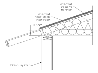
Source: California Energy Commission
A raised heel truss (Figure 8) provides additional height at the attic edge that, depending on the height Y and the ceiling insulation R, can either reduce or eliminate the attic edge area and its thermal impact.
Figure 8: Section at Attic Edge With a Raised Heel Truss
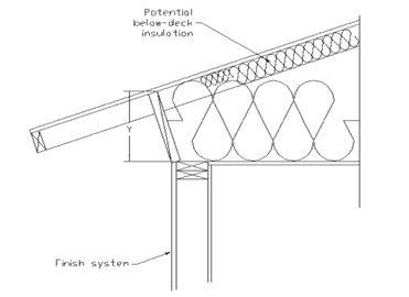
Source: California Energy Commission
For cases where the depth of insulation (including below-deck insulation depth) is greater than the available height at the attic edge, the compliance software automatically creates cathedral ceiling surfaces to represent the attic edge area and adjusts the dimensions of the attic air space using the algorithms contained in the document 2019 Residential Alternative Calculation Method Algorithms. If above-deck insulation is modeled, it is included in the attic edge cathedral ceiling constructions, but radiant barriers below the roof deck are not.
The compliance software shall allow the user to specify that a raised heel truss will be used (as supported by construction drawings), with the default being a standard truss as shown in Figure 7. If the user selects a raised heel truss, the compliance software will require the user to specify the vertical distance between the wall top plate and the bottom of the roof deck (Y in Figure 8).
The standard design shall have a standard truss with the default vertical distance of 3.5 inches between wall top plate and roof deck.
A raised heel truss is a special feature, and the vertical height above the top plate will be included on the CF1R.
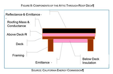
The roof deck is the construction at the top of the attic and includes the solar optic properties of the exterior surface, the roofing type, the framing, insulation, air gaps, and other features. These are illustrated in Figure 9, which shows a detailed section through the roof deck.
2.6.6.1 Radiant Barrier
Radiant barriers are used to reduce heat flow at the bottom of the roof deck in the attic. A 0.05 emittance is modeled at the bottom surface of the roof deck if radiant barriers are used. If no radiant barrier is used, the value modeled is 0.9. If radiant barrier is installed over existing skip sheathing in a reroofing application, 0.5 is modeled.
The user shall specify whether the proposed design has:
•A radiant Barrier
•No Radiant Barrier
The standard design shall have a radiant barrier if required by the prescriptive standards (Section 150.1[c] and Table 150.1-A or 150.1-B) for the applicable climate zone with Option B.
Verification and Reporting
Radiant barriers are reported as a special feature on the CF1R.
2.6.6.2 Below Deck Insulation
Below-deck insulation is insulation that will be installed below the roof deck between the roof trusses or rafters.
The compliance software shall allow the user to specify the R-value of insulation that will be installed below the roof deck between the roof trusses or rafters. The default is an uninsulated roof deck.
The standard design has below-deck insulation as specified in Section 2.5.6.1.
Verification and Reporting
The R-value of any below-deck insulation is reported as a special feature on the CF1R.
2.6.6.3 Roof Deck and Framing
The roof deck is the structural surface that supports the roofing. The compliance software assumes a standard wood deck, and this is not a compliance variable. The size, spacing, and material of the roof deck framing are compliance variables.
The roof deck is wood siding/sheathing/decking. The compliance software shall default the roof deck framing to 2x4 trusses at 24 in. on center. The compliance software shall allow the user to specify alternative framing size, material, and framing spacing.
The standard design is 2x4 trusses at 24 in. on center.
Verification and Reporting
Nonstandard roof deck framing or spacing is reported as a special feature on the CF1R.
2.6.6.4 Above Deck Insulation
Above-deck insulation represents the insulation value of the air gap in “concrete or clay tile” or “metal tile or wood shakes.” The R-value of any user modeled insulation layers between the roof-deck and the roofing is added to the air gap value.
This input defaults to R-0.85 for “concrete or clay tile” or for “metal tile or wood shakes” to represent the benefit of the air gap but no additional insulation. The compliance software shall allow the user to specify the R-value of additional above-deck insulation in any roof-deck construction assembly.
The standard design accounts for the air gap based on roofing type but has no additional above-deck insulation.
Verification and Reporting
Above-deck insulation R-value is reported as a special feature on the CF1R.
2.6.6.5 Roofing Type and Mass
The choice of roofing type determines the air gap characteristics between the roofing material and the deck and establishes whether other inputs are needed, as described below. The choices for roof type are shown below.
•Concrete or clay tile. Both types have significant thermal mass and an air gap between the deck and the tiles.
•Metal tile or wood shakes. These are lightweight but have an air gap between the tiles or shakes and the deck. Note that tapered cedar shingles do not qualify and are treated as a conventional roof surface.
•Other steep-slope roofing types. These include asphalt and composite shingles and tapered cedar shingles. These products have no air gap between the shingles and the structural roof deck.
•Low-slope membranes. These are basically flat roofs with a slope of 2:12 or less.
•Above-deck mass. The above-deck mass depends on the roofing type. The mass is 10 lbs/ft² for concrete and clay tile and 5 lbs/ft² for metal tile, wood shakes, or other steep-slope roofing types. For low-slope roofs, the additional thermal mass is assumed to be gravel or stone, and the user chooses one of the following inputs that is less than or equal to the weight of the material being installed above the roof deck:
•No mass
•5 lbs/ft²
•10 lbs/ft²
•15 lbs/ft²
•25 lbs/ft²
The roof slope shall match the proposed design. The roof type for a steep slope roof is 10 lbs/ft2 tile. The roof type for low-slope roof is lightweight roof.
The roof type is reported on the CF1R.
2.6.6.6 Solar Reflectance and Thermal Emittance
The compliance software shall allow the user to default the solar reflectance and thermal emittance of the roofing. The solar reflectance product default is 0.10 for all roof types. The thermal emittance default is 0.85.
The compliance software shall allow the user to input aged solar reflectance and thermal emittance of roofing material that are rated by the Cool Roof Rating Council. The installed value must be equal to or higher than the value specified here. Roof construction with a roof membrane mass of at least 25 lbs/ft2 or roof area incorporated integrated solar collectors are assumed to meet the minimal solar reflectance.
The solar reflectance and thermal emittance of the standard design roofing are as specified in the prescriptive standards.
Thermal emittance and solar reflectance shall be reported on the CF1R. A reflectance of 0.20 or higher is reported as a cool roof. A value higher than the default but less than 0.20 is reported as a nonstandard roof reflectance value.