
Choosing energy efficient windows, glazed doors, and skylights is one of the most important decisions for any high-performance project. The use of high-performance fenestration can actually reduce energy consumption by decreasing the lighting and heating and cooling loads in nonresidential and high-rise residential buildings. The size, orientation, and types of fenestration products can dramatically affect overall energy performance.
The Energy Standards specify the mandatory and prescriptive features of fenestration products, the performance of fenestration, ratings and labeling by the National Fenestration Rating Council (NFRC), and details on daylighting through skylights.
Windows. A window is a vertical fenestration product that is an assembled unit consisting of a frame and sash component holding one or more pieces of glazing. Window performance is measured with the U-factor, Solar Heat Gain Coefficient (SHGC), and Visible Transmittance (VT).
Windows are considered part of an exterior wall when the slope is 60° or more. When the slope of fenestration is less than 60°, the glazing is considered a skylight and part of the roof.
Skylights and Tubular Daylight Devices. Skylights and tubular daylight devices (TDD) are an exceptional source of daylight and passive solar heating, illuminating rooms with direct and indirect sunlight. In addition, when used appropriately, daylighting can increase the quality of light in a room and reduce dependence upon electrical lighting. Skylights and TDDs don’t typically have the same thermal properties as vertical fenestration and can be prone to greater heat loss in winter and solar heat gain during the summer. When a building designer optimizes the whole envelope glazing arrangement for daylight and thermal control, significant heating and cooling energy savings can be realized, especially when skylights and TDDs are energy efficient.
Glazed Doors. Glazed door is an exterior door having a glazed area of 25 percent or more of the area of the door. When the door has less than 25 percent glazing material, it is no longer considered a glazed door. (See exterior doors in previous section). All glazed areas, will be counted toward the overall glazed area of the conditioned space in any calculations.
There are two options for measuring the glazed area of a door: Count the entire door area for glazed doors or count the area of the glazing in the door plus a 2” frame around the glass (i.e., if you have 1’ by 1’ glazing in a door you would measure the area as 1’4” by 1’4”).
Fenestration Categories
A. Manufactured fenestration is a fenestration product constructed of materials that are factory-cut or otherwise factory-formed with the specific intention of being used to fabricate a fenestration product. Knocked down or partially assembled products may be sold as a fenestration product when provided with temporary and permanent labels, as described in §10-111, or as a site-built fenestration product when not provided with temporary and permanent labels, as described in §10-111.
B. Site-built fenestration is designed to be field-glazed or field-assembled units, using specific factory-cut or other factory-formed framing, and glazing units that are manufactured with the intention of being assembled at the construction site. These include storefront systems, curtain walls or large-track sliding glass walls, and atrium roof systems.
C. Field-fabricated fenestration is when the windows are fabricated at the building site from elements that are not sold together as a fenestration product (that is, separate glazing, framing, and weather stripping elements). Field-fabricated does not include site-assembled frame components that were manufactured elsewhere with the intention of being assembled on site (such as knocked-down products, sunspace kits, and curtain walls).
Additional Fenestration Definitions
Reference Joint Appendix JA1 lists additional terms that relate to fenestration.
A. Center of Glass. U-factor, SHGC, and VT are measured only through glass at least 2.5 inches from the edge of the glass or dividers.
B. Clear glass has little, if any, observable tint.
C. Chromogenic is a class of switchable glazing which includes active materials (e.g. electrochromic) and passive materials (e.g. photochromic and thermochromic) permanently integrated into the glazing assembly
D. Divider (Muntin). An element that actually or visually divides different lites of glass. It may be a true divided lite, between the panes, and/or applied to the exterior or interior of the glazing.
E. Double Pane Window. Double-pane (or dual-pane) glazing is made of two panes of glass (or other glazing material) separated by space (generally 1/4" [6 mm] to 3/4" [18 mm]) filled with air or other gas. Two panes of glazing laminated together do not constitute double-pane glazing
F. Dynamic Glazing. Glazing systems that have the ability to reversibly change their performance properties, including U-factor, solar heat gain coefficient (SHGC), and/or visible transmittance (VT) between well-defined end points. Includes active materials (electrochromic) and passive materials (photochromic and thermochromic) permanently integrated into the glazing assembly. Electrochromatic glass darkens by demand or lightens up when more free daylight or solar heat is desired. Improved glazing decreases the SHGC in the summer and reduces heat loss in the winter and has the ability to reversibly change their performance properties, including U-factor, SHGC, and/or VT between well-defined end points.
G. Integrated shading systems. A class of fenestration products including an active layer: for example, shades, louvers, blinds, or other materials permanently integrated between two or more glazing layers and that has the ability to reversibly change performance properties, including U-factor, SHGC, and/or VT between well-defined end points.
H. Fixed glass. The fenestration product cannot be opened.
I. Gap Width. The distance between glazing in multi-glazed systems (e.g., double-or triple-glazing). This dimension is measured from inside surface to inside surface. Some manufacturers may report "overall" IG unit thickness which is measured from outside surface to outside surface.
J.
Insulating glass unit (IG Unit). An IG unit includes
the glazing, spacer(s), films
(if any), gas infills, and edge caulking.
K. Hard Coat. A pyrolytic low-e coating that is generally more durable but less effective than a soft coat. See separate glossary term for low-e coating.
L. Light or Lite. A layer of glazing material, especially in a multi-layered IG unit. Referred to as panes in §110.6 when the lites are separated by a spacer from inside to outside of the fenestration.
M. Low-e Coatings. Low-emissivity coatings are special coatings applied to the second, third or fourth surfaces in double-glazed windows or skylights. As the name implies the surface has a low emittance. This means that radiation from that surface to the surface it “looks at” is reduced. Since radiation transfer from the hot side of the window to the cool side of the window is a major component of heat transfer in glazing, low-e coatings are very effective in reducing the U-factor. They do nothing, however, to reduce losses through the frame.
Low-e coatings can be engineered to have different levels of solar heat gain. Generally, there are two kinds of low-e coatings:
1. Low solar gain low-e coatings are formulated to reduce air conditioning loads. Fenestration products with low solar gain low-e coatings typically have an SHGC of 0.40 or less. Low-solar gain low-e coatings are sometimes called spectrally selective coatings because they filter much of the infrared and ultra-violet portions of the sun’s radiation while allowing visible light to pass through.
2. High solar gain low-e coatings, by contrast, are formulated to maximize solar gains. Such coatings would be preferable in passive solar applications or where there is little air conditioning.
Another advantage of low-e coatings, especially low solar gain low-e coatings, is that when they filter the sun’s energy, they generally remove between 80 percent and 85 percent of the ultraviolet light that would otherwise pass through the window and damage fabrics and other interior furnishings.
N. Mullion. A frame member that is used to join two individual windows into one fenestration unit.
O. Nonmetal Frame. Includes vinyl, wood, or fiberglass. Vinyl is a polyvinyl chloride (PVC) compound used for frame and divider elements with a significantly lower conductivity than metal and a similar conductivity to wood. Fiberglass has similar thermal characteristics. Non-metal frames may have metal strengthening bars entirely inside the frame extrusions or metal-cladding only on the surface.
P. Operable. The fenestration product can be opened for ventilation.
Q. Soft Coat. A low-e coating applied through a sputter process. See separate glossary term for low-e coating.
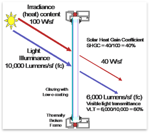
R. Solar Heat Gain Coefficient (SHGC). A measure of the relative amount of heat gain from sunlight that passes through a fenestration product. SHGC is a number between zero and one that represents the ratio of solar heat that passes through the fenestration product to the total solar heat that is incident on the outside of the window. A low SHGC number (closer to 0) means that the fenestration product keeps out most solar heat. A higher SHGC number (closer to 1) means that the fenestration product lets in most of the solar heat. SHGC or SHGCt is the SHGC for the total fenestration product and is the value used for compliance with the Standards.
S. Spacer or Gap Space. A material that separates multiple panes of glass in an insulating glass unit.
T. Thermal Break Frame. Includes metal frames that are not solid metal from the inside to the outside, but are separated in the middle by a material, usually vinyl or urethane, with a significantly lower conductivity.
U. Tinted. Darker gray, brown or green visible tint. Also, low-e or IG unit with a VT less than 0.5.
V. U-factor. A measure of how much heat can pass through a construction assembly or a fenestration product. The lower the U-factor, the more energy efficient the product is. The units for U-factor are Btu of heat loss each hour per square foot (ft2) of window area per degree °F of temperature difference (Btu/hr-ft²-°F). U-factor is the inverse of R-value. The U-factor considers the entire product, including losses through the center of glass, at the edge of glass where a metal spacer typically separates the double-glazing panes, losses through the frame, and through the mullions. For metal-framed fenestration products, the frame losses can be significant.
W. Visible Transmittance (VT) is the ratio of visible light transmitted through the fenestration. The higher the VT rating, the more light is allowed through a window.
X. Window Films are composed of a polyester substrate to which a special scratch resistant coating is applied on one side, with a mounting adhesive layer and protective release liner applied to the other side.
Example 3-11
Question:
What
constitutes a double-pane window?
Answer:
Double-pane
(or dual-pane) glazing is made of two panes of glass (or other glazing material)
separated by a space [generally ¼ inch (6 mm) to ¾ inch (18 mm)] filled with air
or other inert gases. Two panes of glazing laminated together do not constitute
double-pane glazing, but are treated as single pane.
The mandatory measures for windows, glazed doors, and skylights address product certification and labeling, the air-tightness of the units (air leakage), how to determine the U-factor, solar heat gain coefficient (SHGC), and visible transmittance (VT).
A fenestration product or glazed door, other than field-fabricated fenestration products and field-fabricated glazed doors, may be installed if an independent certifying organization approved by the Energy Commission has certified that the product complies or if the manufacturer has certified to the Energy Commission by using a default label.
3.3.2.1 Certification and Labeling
The Administrative Regulations §10-111 and §110.6 require that fenestration products have labels that list the U-factor, SHGC, VT and the method used to determine those values. The label must also certify that the fenestration product meets the requirements for air leakage from §110.6(a)1.
A. Manufactured (Factory-Assembled) Fenestration Label Certificates
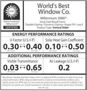
Figure 3-9: NFRC Manufactured Label
Each manufactured (factory-assembled) fenestration product must have a clearly visible temporary label attached to it (Figure 3-9), which is not to be removed before inspection by the enforcement agency. The manufacturer rates and labels its fenestrations products for U-factor, SHGC and VT.
2. The manufacturer can choose to have the fenestration product rated and labeled in accordance with the NFRC Rating Procedure (NFRC 100 for U-factors and NFRC 200 for SHGC and VT). If the manufactured fenestration product is rated using the NFRC rating procedure, it must also be permanently labeled in accordance with NFRC procedures.
B. Default Temporary Label
Fenestration product manufacturers can choose to use default performance values for U-factors in Table 110.6-A and SHGC in Table 110.6-B. (Table 3-14 and Table 3-15) For fenestration products requiring a VT value, assume a value of 1.0 as specified in the Reference Nonresidential Appendix NA6. The manufacturer must attach a temporary label to each window (See Figure 3-11), and manufacturer specification sheets or cut sheets must be included with compliance documentation. A NRCC-ENV-05-E will be required to document the thermal performance if no default temporary labels are attached to the window units.
There is no exact format for the default temporary label. It must be clearly visible and large enough to be clearly visible from 4 feet for the enforcement agency field inspector to read easily. It must include all information required by the regulations. The minimum suggested label size is 4 in. x 4 in., and the label must have the following words at the bottom of the label.
“Product meets the air infiltration requirements of §110.6(a)1, U-factor criteria of §110.6(a)2, SHGC criteria of §110.6(a)3 and VT criteria of §110.6(a)4 of the 2019 California Building Energy Efficiency Standards for Residential and Nonresidential Buildings.”
If the product claims the default U-factor for a thermal-break product, the manufacturer must certify that the thermal-break criteria upon which the default value is based are met by placing a check in the check box:
1. Air space 7/16 in. or greater
2. For skylights, the label must indicate the product was rated with a built-in curb
3. Meets thermal-break default criteria
Figure 3-10:
Sample Default Temporary Label
|
2019 California Energy Commission Default Label XYZ Manufacturing Co. | ||
|
Key Features: |
o Doors |
o Double-Pane |
|
o Skylight |
o Glass Block | |
|
|
|
|
|
Frame Type |
Product Type: |
Product Glazing Type: |
|
o Metal |
o Operable |
o Clear |
|
o Non-Metal |
o Fixed |
o Tinted |
|
o Metal, Thermal Break |
o Greenhouse/Garden Window |
o Single-Pane |
|
o Air space 7/16 in. or greater o With built-in curb o Meets Thermal-Break Default Criteria |
---------- |
To calculate VT see NA6 |
|
California Energy Commission Default U-factor = |
California Energy Commission Default SHGC = |
California Energy Commission Calculated VT = |
|
Product meets the air infiltration requirements of §110.6(a)1, U-factor criteria of §110.6(a)2, SHGC criteria of §110.6(a)3 and VT criteria of §110.6(a)4 of the 2019 Energy Standards for Residential and Nonresidential Buildings. | ||
For the visible transmittance (VT) of diffusing skylights that is not covered by NFRC 200 or NFRC 203, a test report should be included using the ASTM E972 method.
C. Component Modeling Approach (CMA)
NFRC has developed a performance base calculation, the component modeling approach (CMA), to make the rating process quick and simple. This serves as an energy ratings certification program for fenestration products used in nonresidential projects. The CMA allows users to assemble fenestration products in a virtual environment. CMA draws data for NFRC-approved components from online libraries choosing from preapproved glazing, frame, and spacer components. CMA users are able to obtain preliminary ratings for various configurations of their designs. CMA is a fair, accurate, and credible method based on NFRC 100 and 200 program documents, which are verified by third-party rating procedures. This tool helps users to:
1. Design energy-efficient windows, curtain wall systems, and skylights for high-performance building projects.
2. Determine whether a product meets the specifications for a project and local/state building energy codes.
3. Model different fenestration designs to compare energy performance.
Once the user is satisfied with the product, they
create a bid report containing the data for all fenestration products to be
reviewed. The windows are then built, either on-site or in a factory. The final
products are reviewed and are rated by an NFRC-approved calculation entity (ACE) and a license
agreement is signed with NFRC. Then the NFRC
issues a CMA label certificate for the project. This label certificate is a
document that lists the certified fenestration ratings at the NFRC standard testing
size for the entire building project. Once approved, the CMA label
certificate is available online immediately. This certificate serves as code
compliance documentation for fenestration energy performance, and the certified
products may be applied to future projects without repeating the certification
process.
Benefits of CMA. CMA provides facility managers, specifiers, building
owners, and design teams with a simple method for designing and certifying the
energy performance of fenestration systems for their buildings without having to test every possible variation of
glazing and framing. This is significantly less expensive than building
sample wall sections and testing them in a large test enclosure. There are
several additional advantages gained by using the CMA:
1. CMA’s online tool has the ability to output a file with values for use in building energy analysis software programs.
2. The program can export detailed information for angular-dependent SHGC and VT values, seamlessly transferring the data to the analytical software.
3. A 2010 study1 conducted in California demonstrated that fenestration modeled with the CMA program can provide an increase in compliance margins by as much as 11.7 percent over the Energy Standard’s default calculation methods.
4. CMA can help demonstrate above-code performance, which is useful for environmental rating programs such as Leadership in Energy and Environmental Design (LEED™) or local green building programs.
Use of the CMA can lead to a more efficient building and enable cost savings due to more accurate fenestration performances and potential energy benefits from above-code utility incentives. Details are available at www.NFRC.org.
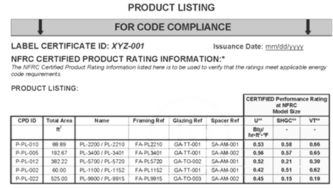
Figure 3-11: NFRC - CMA Label Certificate, Page 1
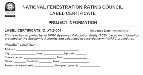
Figure 3-11A: NFRC - CMA Label Certificate, Page 2
D. Fenestration Certificate NRCC-ENV-05-E
For nonrated products where no default label certificates are placed on the fenestration product, use Fenestration Certificate NRCC-ENV-05-E to document thermal performances of each fenestration product that results in a different U-factor, SHGC, and VT. Alternatively, one certificate will suffice when all the windows are the same.
The NRCC-ENV-05-E should indicate the total amount of non-NFRC-rated fenestration products throughout the project. The locations and orientations where fenestration products are being installed should be indicated on the drawings and in a fenestration schedule that lists all fenestration products.
The NRCC-ENV-05-E should clearly identify the appropriate table or equation that is used to determine the default U-factor and SHGC and, if applicable, the center of glass, SHGCC, used in calculating the SHGCfen. Manufacturer’s documentation of these product characteristics that list the center-of-glass values must also be attached to the NRCC-ENV-05-E and located at the job site for verification.
E. Site-Built Label Certificates
Site-built fenestration is field-assembled using specific factory-cut or factory-formed framing and glazing units that are manufactured with the intention of being assembled at the construction site or glazing contractor’s shop.
1. For site-built fenestration totaling 200 ft2 or greater, the glazing contractor or specifier must generate a NFRC label certificate from either approach listed below:
a. A NFRC label certificate generated by the CMA computer program.
b. Default to the U-factor values from Table 110.6-A, the SHGC values from 110.6-B and for VT values, use the method specified in NA6.
2. For site-built fenestration totaling less than 200 ft² or any area of replacement of site-built fenestration that includes vertical windows, glazed doors, and skylights, the glazing contractor or specifier must comply with one of the following:
a. A NFRC label certificate generated by the CMA computer program.
b. The center-of-glass values from the manufacturer’s product literature to determine the total U-factor, SHGC and VT. (See Reference Nonresidential Appendix NA6 - the Alternative Default Fenestration Procedure).
c. The U-factor values from Table 110.6-A and SHGC values from Table 110.6-B. For VT values, use the method specified in NA6.
NA6 calculations are based on center-of-glass (COG) values from the manufacturer. For example, when using a manufacturer’s SHGC center-of-glass specification of 0.27, the NA6 calculation results in an overall SGHC value of 0.312, which may be rounded to 0.31. Rounding to the nearest hundredth decimal place is acceptable to determine the overall fenestration efficiency value with either the prescriptive or performance approach.
Site-built certificates should be filed at the contractor’s project office during construction or in the building manager’s office. Site-built fenestration has multiple responsible parties. The steps of producing site-built fenestration are as follows:
1. Architects and/or engineers design the basic glazing system by specifying the components, the geometry of the components, and, sometimes, the assembly method.
2. An extrusion manufacturer provides the mullions and frames that support the glazing and is responsible for thermal breaks.
3. A glazing manufacturer provides the glazing units, cut to size and fabricated as insulated glass (IG) units. The glazing manufacturer is responsible for tempering or heat strengthening, the tint of the glass, any special coatings, the spacers, and the sealants.
4. A glazing contractor (usually a subcontractor to the general contractor) puts the system together at the construction site, or the contractor’s shop and is responsible for many quality aspects. Predetermining the energy performance of site-built fenestration as a system is more challenging than for manufactured units.
5. One of the parties (architect, glazing contractor, extrusion manufacturer, IG fabricator, or glass manufacturer) must take responsibility for testing and labeling of the site-built fenestration system under the most recent NFRC 100 procedure. The responsible party must obtain a label certificate as described in §10-111.
6. The glazing contractor or other appropriate party assumes responsibility for acquiring the NFRC label certificate. Each label certificate has the same information as the NFRC temporary label for manufactured products but includes other information specific to the project, such as the name of the glazing manufacturer, the extrusion contractor, the places in the building where the product line is used, and other details.
It is typical for the glazing contractor to assume responsibility and to coordinate the certification and labeling process. The design team may include language in the contract with the general contractor that requires that the general contractor be responsible. The general contractor typically assigns this responsibility to the glazing contractor, once the responsible party has established a relationship with the NFRC.
It is not necessary to complete the NFRC testing and labeling prior to completing the building permit application. Designers should specify the type of glass and whether the frame has a thermal break or is thermally improved. Plans examiners should verify that the fenestration performance shown in the plans and used in the compliance calculations is reasonable and achievable, by consulting the default values for U-factor and SHGC in Reference Nonresidential Appendix NA6.
F. Field-Fabricated Fenestration and Field-Fabricated Exterior Door
Field-fabricated fenestration is fenestration assembled on site that does not qualify as site-built fenestration. It includes windows where wood frames are constructed from raw materials at the building site, salvaged windows that do not have an NFRC label or rating, and other similar fenestration items.
No attached labeling is required for field-fabricated fenestration products; only the NRCC-ENV-05-E with the default values is required. Field-fabricated fenestration and field-fabricated exterior doors may be installed only if the documentation has demonstrated compliance with the Energy Standards.
For field-fabricated fenestration, the U-factor and SHGC default values can be found in Table 3-12 and Table 3-13, respectively, below. Values are determined by frame type, fenestration type, and glazing composition.
Exterior doors with glazing for 25 percent or more of the door area are treated as fenestration products and must meet all requirements and ratings associated with fenestration. When a door has glazing of less than 25 percent the door area, the portion of the door with fenestration must be treated as part of the envelope and fenestration independent of the remainder of the door area.
The field inspector is responsible for ensuring field-fabricated fenestration meets the specific U-factor, SHGC, and VT, as listed on the NRCC-ENV-05-E. Thermal break values do not apply to field-fabricated fenestration products.
|
FRAME |
PRODUCT TYPE |
SINGLE |
DOUBLE |
GLASS BLOCK 2,3 |
|
Metal |
Operable |
1.28 |
0.79 |
0.87 |
|
Fixed |
1.19 |
0.71 |
0.72 | |
|
Greenhouse/garden window |
2.26 |
1.40 |
N.A. | |
|
Doors |
1.25 |
0.77 |
N.A. | |
|
Skylight |
1.98 |
1.30 |
N.A. | |
|
Metal, Thermal Break |
Operable |
N.A. |
0.66 |
N.A. |
|
Fixed |
N.A. |
0.55 |
N.A. | |
|
Greenhouse/garden window |
N.A. |
1.12 |
N.A. | |
|
Doors |
N.A. |
0.59 |
N.A. | |
|
Skylight |
N.A. |
1.11 |
N.A. | |
|
Nonmetal |
Operable |
0.99 |
0.58 |
0.60 |
|
Fixed |
1.04 |
0.55 |
0.57 | |
|
Doors |
0.99 |
0.53 |
N.A. | |
|
Greenhouse/garden windows |
1.94 |
1.06 |
N.A. | |
|
Skylight |
1.47 |
0.84 |
N.A. | |
|
1. For all dual-glazed fenestration products, adjust the listed U-factors as follows: | ||||
|
a. Add 0.05 for products with dividers between panes if spacer is less than 7/16 inch wide. | ||||
|
b. Add 0.05 to any product with true divided lite (dividers through the panes). | ||||
|
2. Translucent or transparent panels shall use glass block values when not rated by NFRC 100. | ||||
|
3. Visible transmittance (VT) shall be calculated by using Reference Nonresidential Appendix NA6. | ||||
|
4. Windows with window film applied that is not rated by NFRC 100 shall use the default values from this table. | ||||
Table 110.6-A of the Energy Standards
|
FRAME TYPE |
PRODUCT |
GLAZING |
FENESTRATION PRODUCT SHGC | ||
|
Single Pane2,3 |
Double Pane2,3 |
Glass Block1,2 | |||
|
Metal |
Operable |
Clear |
0.80 |
0.70 |
0.70 |
|
Fixed |
Clear |
0.83 |
0.73 |
0.73 | |
|
Operable |
Tinted |
0.67 |
0.59 |
N.A. | |
|
Fixed |
Tinted |
0.68 |
0.60 |
N.A. | |
|
Metal, Thermal Break |
Operable |
Clear |
N.A. |
0.63 |
N.A. |
|
Fixed |
Clear |
N.A. |
0.69 |
N.A. | |
|
Operable |
Tinted |
N.A. |
0.53 |
N.A. | |
|
Fixed |
Tinted |
N.A. |
0.57 |
N.A. | |
|
Nonmetal |
Operable |
Clear |
0.74 |
0.65 |
0.70 |
|
Fixed |
Clear |
0.76 |
0.67 |
0.67 | |
|
Operable |
Tinted |
0.60 |
0.53 |
N.A. | |
|
Fixed |
Tinted |
0.63 |
0.55 |
N.A. | |
|
1. Translucent or transparent panels shall use glass block values when not rated by NFRC 200. 2. Visible transmittance (VT) shall be calculated by using Reference Nonresidential Appendix NA6. 3. Windows with window film applied that is not rated by NFRC 200 shall use this table’s default values | |||||
Table 110.6-B of the Energy Standards
3.3.2.2 Determining Fenestration Performance
A. U-Factor
The preferred methods for determining fenestration U-factor are those in NFRC 100 for manufactured windows and for site-built fenestration. The default U-factors in Table 110.6-A must be used when a NFRC label for the U-factor is not available (Table 3-14). The U-factors in Table 110.6-A represent the least efficient possible values, thereby encouraging designers to obtain ratings through NFRC test procedures, when they are available.
B. Solar Heat Gain Coefficient (SHGC)
For the SHGC, the methods determining the preferred values are in NFRC 200. If they are not available, Table 110.6-B of the Energy Standards (Table 3-14) must be used for default values.
|
U-factor and SHGC |
Fenestration Category | ||||
|
Determination Method |
Manufactured Windows |
Manufactured Skylights |
Site-Built Fenestration (Vertical& |
Field-Fabricated Fenestration |
Glass Block |
|
ü |
ü |
ü |
N/A |
N/A | |
|
NFRC-100 |
ü |
ü |
ü |
N/A |
N/A |
|
Default Tables 110.6-A (U-factor) 110.6-B (SHGC) |
ü |
ü |
ü |
ü |
ü |
|
NA62 |
N/A |
N/A |
ü |
N/A |
N/A |
|
1The NFRC Residential CMA method is an option that may be available in the Energy Standards. 2The Alternative Default U-factors from Nonresidential Reference Nonresidential Appendix NA6 may only be used for site-built vertical and skylights having less than 200 ft2. | |||||
The visible transmittance (VT) of the fenestration shall be rated in accordance with NFRC 200 or ASTM E972. More specifically, the NFRC 200 test method is appropriate only for flat, clear glazing and does not cover curved glazing or diffusing glazing. NFRC 202 is the approved test method for rating the visible transmittance of planar diffusing glazing such as is used in fiberglass insulating fenestration. NFRC 203 is the approved test method for rating the visible transmittance of tubular skylights, also known as tubular daylighting devices (TDDs). For other types of fenestration, including dome skylights, use ASTM E972 to rate the visible transmittance.
VT is a property of glazing materials that has a varying relationship to SHGC (Figure 3-12). The ideal glazing material for most hot climates would have a high VT and a low SHGC. Such a glazing material allows solar radiation in the visible spectrum to pass while blocking radiation in the infrared and ultraviolet spectrums. Materials that have this quality are labeled “spectrally selective” and have a VT that is up to 2.2 times the SHGC.
Figure 3-12: Solar Heat Gain Coefficient and Visible Transmittance
3.3.2.3 Air Leakage
Manufactured and site-built fenestration such as doors and windows must be tested and shown to have infiltration rates not exceeding the values shown in Table 3-15. For field-fabricated products or exterior doors, the Energy Standards require that the unit be caulked, gasketed, weather stripped, or otherwise sealed. Unframed glass doors and fire doors are the two exceptions to these air leakage requirements.
|
Class |
Type |
Rate |
|
Windows (cfm/ft²) of window area |
All |
0.3 |
|
Residential Doors (cfm/ft²) of door area |
Swinging, Sliding |
0.3 |
|
All Other Doors (cfm/ft²) of door area |
Sliding, Swinging (single door) |
0.3 |
|
Swinging (double door) |
1.0 |
Example 3-12
Question:
A 150,000 ft² “big box” retail store has 800 ft² of site-built vertical fenestration at the entrance. An operable double-pane aluminum storefront framing system is used without a thermal break. What are the acceptable methods for determining the fenestration U-factor and SHGC? What are the labeling requirements assuming a center of glass U-factor of 0.50 and SHGC of 0.70 and a center glass visible transmittance of 0.75?
Answer:
For site-built fenestration
less than 200 ft2 then one of the following three methods may be used:
1.
Rate the fenestration using the component modeling approach (CMA), which will yield the most efficient
values possible.
2. Use the default U-factor and SHGC values from equations
in Reference Nonresidential Appendix NA6:
l U-factor may be calculated from NA6, Equation NA6-1,
UT = C1 + C2 X UC. From Table NA-1 for metal–framed, site-built fenestration,
C1= 0.311 and C2 = 0.872, therefore the overall U-factor
is calculated to be 0.311 + 0.872 x 0.50 = 0.47.
l SHGC is determined from NA6, Equation NA6-2,
SHGCT = 0.08 + 0.86 x SHGCC. The SHGC is calculated to be
0.08 + 0.86 x 0.70 = 0.68.
l VT from NA6, the visible transmittance of the
frame is 0.88 for a curtain wall, so the VTT = VTF X
VTC = 0.88 X 0.75 = 0.66.
Select from default Tables 110.6-A and 110.6-B of the Energy Standards. From these tables, the U-factor is 0.79 and the SHGC is 0.70. A Fenestration Certificate Label, NRCC-ENV-05-E, should be completed for each fenestration product. Or the responsible party may attach a default temporary label to each fenestration unit throughout the building.
3.3.3.1 Prescriptive Measures
There are four aspects of the envelope component approach for windows:
1. Maximum total area plus west-facing.
2. Maximum U-factor.
3. Maximum relative solar heat gain coefficient (RSHGC).
4. Minimum visible transmittance (VT).
A. Window Area
In the prescriptive approach, the total window area may not exceed 40 percent of the gross wall area (encompassing total conditioned space) for the building. Likewise, the west-facing window area may not exceed 40 percent of the west gross wall area (encompassing total conditioned space for the building). This maximum area requirement will affect those buildings with very large glass areas, such as high-rise offices, automobile showrooms, or airport terminals.
The maximum area may be determined by multiplying the length of the display perimeter by 6 feet in height and use the larger of the product of that multiplication or 40 percent of gross exterior wall area.
Display perimeter is the length of an exterior wall in a Group B; Group F, Division 1; or Group M occupancy that immediately abuts a public sidewalk, measured at the sidewalk level for each story that abuts a public sidewalk. This generally refers to retail display windows, although other occupancies such as offices can also have a display perimeter. Public sidewalks are accessible to the public at large (no obstructions, limits to access, or intervening nonpublic spaces). Demising walls are not counted as part of the display perimeter.
Glazing in a demising wall does not count toward the total building allowance. There is no limit to the amount of glazing allowed in demising walls, but it must meet the prescriptive U-factorrequirements for the climate zone.
Window area is generally taken from the rough opening dimensions. To the extent this opening is slightly larger than the frame, the rough opening area will be slightly larger than the formally defined window area.
Glazed doors, use the rough opening area, except where the door glass area is less than 50 percent of the door, in which case the glazing area may be either the entire door area or the glass area plus 2 inches added to all four sides of the glass (to represent the “window frame”) for a window in a door. Calculate the window area from the rough opening dimensions and divide by the gross exterior wall area, which does not include demising walls.
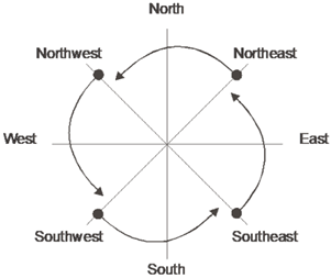
The orientation can be determined from an accurate site plan. Any orientation within 45 degrees of true north, east, south, or west will be assigned to that orientation. Figure 3-13 demonstrates how surface orientations are determined and what to do if the surface is oriented exactly at 45 degrees of a cardinal orientation. For example, an east-facing surface cannot face exactly northeast, but it can face exactly southeast. If the surface were facing exactly northeast, it would be considered north-facing.
Figure 3-13: Four Surface Orientations
B. Window U-Factor
§140.3(a)5B, TABLES 140.3-B,C
Fenestration products must meet the prescriptively required maximum U-factor criteria in Tables 140.3-B and Table 140.3-C of the Energy Standards (Table 3-16) for each climate zone. Most NFRC-rated multi-glazed windows with a low-e coating and a thermally broken frame will comply with the U-factor criterion. See http://www.nfrc.org, Certified Product Directory database, or use Equation NA6-1 found in Reference Nonresidential Appendix NA6.
|
|
All Climate Zones | ||||
|
Space Type |
Criterion |
Operable |
Curtainwall/ Storefront |
Glazed | |
|
Nonresidential |
Max U-factor |
0.36 |
0.46 |
0.41 |
0.45 |
|
Max Relative Solar Heat Gain (RSHGC) |
0.25 |
0.22 |
0.26 |
0.23 | |
|
Min VT |
0.42 |
0.32 |
0.46 |
0.17 | |
|
Maximum WWR% |
40% | ||||
|
|
All Climate Zones | ||||
|
Residential |
Max U-Factor |
0.36 |
0.46 |
0.41 |
0.45 |
|
Max Relative Solar Heat Gain (RSHGC) |
0.25 |
0.22 |
0.26 |
0.23 | |
|
Min VT |
0.42 |
0.32 |
0.46 |
0.17 | |
|
Maximum WWR% |
40% | ||||
|
From Energy Standards Tables 140.3-B and Table 140.3-C | |||||
C. SHGC and Overhang Factor
Relative solar heat gain (RSHGC) allows for an external shading correction. It is calculated by multiplying the SHGC of the fenestration product by an overhang factor. If an overhang does not exist, then the overhang factor is 1.0. Relative solar heat gain is applicable only when using the prescriptive compliance approach. Tables 140.3-B and Table 140.3-C specify the maximum area-weighted average RSHGC, excluding the effects of interior shading. (Table 3-16)
Figure 3-14: Overhang Dimensions
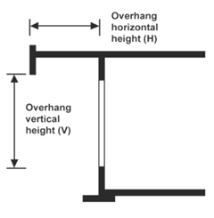
Overhang factors may either be calculated or taken from Table 3-17 and depend upon the ratio of the overhang horizontal length (H) and the overhang vertical height (V). These dimensions are measured from the vertical and horizontal planes passing through the bottom edge of the window glazing, as shown in Figure 3-14. An overhang factor may be used if the overhang extends beyond both sides of the window jamb a distance equal to the overhang projection (§140.3(a)5Cii). The overhang projection is equal to the overhang length (H), see Figure 3-14. If the overhang is continuous along the side of a building, this restriction will usually be met. If there are overhangs for individual windows, each must be shown to comply.
Equation 3-1 – Relative Solar Heat Gain Coefficient
RSHGC = SHGCwin x OHF
Where:
RSHGC = Relative solar heat gain Coefficient
SHGCwin = Solar heat gain coefficient of the window
Equation 3-2 – Overhang Factor
Where:
H = Horizontal projection of the overhang from the surface of the window in feet, but no greater than V
V = Vertical distance from the windowsill to the bottom of the overhang, in feet.
a = -0.41 for north-facing windows, -1.22 for south-facing windows, and -0.92 for east- and west-facing windows
b =0.20 for north-facing windows, 0.66 for south-facing windows, and 0.35 for east- and west-facing windows
|
H/V |
North |
South |
East/West |
|
0.00 |
1.00 |
1.00 |
1.00 |
|
0.10 |
0.96 |
0.88 |
0.91 |
|
0.20 |
0.93 |
0.78 |
0.83 |
|
0.30 |
0.90 |
0.69 |
0.76 |
|
0.40 |
0.87 |
0.62 |
0.69 |
|
0.50 |
0.85 |
0.56 |
0.63 |
|
0.60 |
0.83 |
0.51 |
0.57 |
|
0.70 |
0.81 |
0.47 |
0.53 |
|
0.80 |
0.80 |
0.45 |
0.49 |
|
0.90 |
0.79 |
0.44 |
0.46 |
|
1.00 or greater |
0.79 |
0.44 |
0.43 |
Any value of H/V greater than 1 has the same overhang factor (for a given orientation) shown in the last row of Table 3-17.
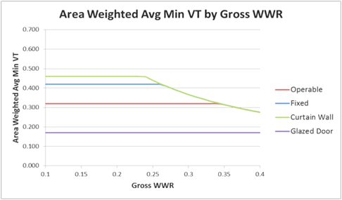
Figure 3-15 illustrates the benefits of overhang factors of the various orientations as a function of H/V. The graph shows that overhangs have only a minor effect on the north. (Maximum reduction in SHGC is only about 20 percent.) East, west, and south overhangs can achieve reductions of 55–60 percent. The benefits of the overhang level off as the overhang becomes larger.
Figure 3-15: Graph of Overhang Factors

Example 3-13
Question:
An east-facing window has glass with
a solar heat gain coefficient of 0.71. It has a fixed overhanging eave that extends 3
feet out from the plane of the glass (H = 3) and is 6 feet above the bottom of
the glass
(V = 6). The overhang extends more than 3 feet beyond each side of
the glass, and the top of the window is less than 2 feet vertically below the
overhang. What is the RSHGC for this window?
Answer:
First,
calculate H/V. This value is 3 / 6 = 0.50. Next, find the overhang factor from
Table 3-18. For east-facing windows, this value is 0.63. Finally, multiply it by
the solar heat gain coefficient to obtain the RSHGC: 0.63 x 0.71 =
0.45.
D. Visible Light Transmittance (VT)
The prescriptive requirements of Tables 140.3-B and Table 140.3-C (Table 3-16) of the Energy Standards prescribe specific VT values for all climate zones and glass types. The visible light transmittance is used in the performance method in the calculation of the interior illumination levels and lighting energy savings due to daylight controls. The performance method is discussed in more detail in Chapter 5.
Fenestration must meet the climate zone-specific prescriptive requirement of having an area-weighted average VT of 0.42 or greater for fixed windows, 0.32 or greater for operable windows, 0.46 or greater for curtain walls and 0.17 or greater for glazed doors. Products with spectrally selective “low-e” coatings (also known as single, double or triple silver low-e) are available to meet this requirement.
A combination of high VT glazing in the upper part of a window (clerestory) and lower VT glazing at the lower part of the window (view window) can be used, as long as the area-weighted average meets the prescriptive requirement. This allows daylight to enter the space through the high VT glazing making a better daylighting design.
The Energy Standards also allow a slight variance if the window-to-wall ratio (WWR) is greater than 40 percent. For this case, assume 0.40 for the WWR in the equation below or the glazing can comply with the prescriptive requirements if the area-weighted average VT meets the following minimum requirement:
Equation 3-3 – Visible Light Transmittance
VT ≥ 0.11 / WWR
Where:
VT = the visible transmittance of the framed window
WWR = the gross window-to-wall ratio
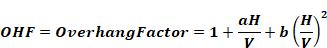
The graph in Figure 3-16 shows the allowed area weighted average minimum VT’s by gross WWR for four types of windows. The average VT requirements apply separately to chromatic (dynamic or color changing) glazing and nonchromatic glazing. For chromatic glazing, higher ranges of VT can be used to meet the prescriptive requirements. All glazing that is not chromatic must separately meet the area-weighted VT prescriptive requirements.
Figure 3-16: Area Weighted Average Minimum VT by Gross Window-to-Wall Ratio
![]()
Example 3-14
Question:
 A space has a gross
window-to-wall ratio of 30 percent and has a fixed window with a sill height of
2’6” (30”) and a head height of 8’11” (107”), which runs 10’ wide (120”). The
window has a break at 6’11” (83”) such that the upper portion or clerestory
portion of the window is 2’ (24”) tall and can have a glazing different from
that in the lower portion (view window). Can a designer use 0.30 VT glazing in
the view window?
A space has a gross
window-to-wall ratio of 30 percent and has a fixed window with a sill height of
2’6” (30”) and a head height of 8’11” (107”), which runs 10’ wide (120”). The
window has a break at 6’11” (83”) such that the upper portion or clerestory
portion of the window is 2’ (24”) tall and can have a glazing different from
that in the lower portion (view window). Can a designer use 0.30 VT glazing in
the view window?
Answer:
Use the formula VT ≥ 0.11 / WWR, to determines the minimum area weighted average VT for this space,
VT ≥ 0.11 / 0.3 = 0.367. The area weighted minimum VT we need for this window is 0.367.
(View window Area x View window VT) + (Clerestory Area x Clerestory VT) / Total Window Area = 0.367
In this case:
Clerestory area = 24” height x 120” width = 2,880 sq.in
View window area = (83” - 30”) height x 120” width = 6,360 sq.in.
Using a 0.30 VT glazing in the view window then View window VT = 0.30
Total window area = (107” - 30”) height x 120” width = 9,240 sq.in.
Solve the equation for Clerestory VT: Clerestory VT = 0.515
(6360 x 0.367) + (2880 x VTCL)/9240
To use a 0.3 VT glazing in the view window, the designer must use a 0.515 VT window in the clerestory.
Example 3-15
Question:
A designer is using a U-factor of 0.57 for compliance with a curtain wall system. The glazing system uses two lites of 1/4 in (6mm) glass with a low-e= 0.1 coating on the second surface. The air gap is 1/2 in (12 mm). A standard metal frame is proposed for the curtain wall system. Is 0.57 a reasonable U-factor for compliance, and can it reasonably be achieved by the glazing contractor through the NFRC process for site-built fenestration?
Answer:
No. If there is no NFRC rating, the default U-factor must be used for this glazing combination from Reference Nonresidential Appendix NA6 is 0.59. The design U-factor of 0.57 cannot be used.
3.3.3.2 Compliance Options
A. Dynamic Glazing − Chromatic Glazing
Chromatic-type fenestration has the ability to change performance properties (U-factor, SHGC, and VT). The occupant can manually or automatically control his or her environment by tinting or darkening a window with the flip of a switch or by raising/lowering a shade positioned between panes of glass. Some windows and doors change the performance automatically in response to a control or environmental signal. These smart windows provide a variety of benefits, including reduced energy costs due to controlled daylighting and unwanted heat gain or heat loss.
Look for NFRC Dynamic Glazing Labels to compare and contrast the energy performance for these products. See Figure 3-17. The unique rating identifiers help consumers understand the dynamics of the product and allow comparison with other similar fenestration products. If the product can operate at intermediate states, a dual directional arrow, (↔), with the word variable underneath will appear on the label. Some dynamic glazing is able to adjust to intermediate states, allowing for a performance level between the endpoints. The low value rating is displayed to the left (in the closed position), and the high value rating is displayed to the right (in the open position). This lets the consumer know at a glance the best and worst case performance of the product and what the default or de-energized performance level will be.
Figure 3-17: Dynamic Glazing NFRC Label
To receive chromatic glazing credit, the following must be met:
1. Optional prescriptive U-factor and SHGC from Tables 140.3-B and Table 140.3-C
2. Performance approach compliance gives maximum credit allowance for best rating
3. Automatic controls to receive best rating values or
4. NFRC Dynamic Glazing Compliance Label is required. Otherwise, default to Table 110.6-A and 110.6-B values.
B. Window Films
Window films are made of mostly polyester substrate that is durable, tough, and highly flexible. It absorbs little moisture and has both high and low temperature resistances. Polyester film offers clarity and can be pretreated to accept different types of coatings for energy control and long-term performance. Window films are made with a special scratch-resistant coating on one side and with a mounting adhesive layer on the other side. The adhesive is normally applied to the interior surface (room side) of the glass, unless a film is specifically designed to go on the exterior window surface. Film can be metalized and easily laminated to other layers of polyester film.
There are three basic categories of window films:
1. Clear (nonreflective) films are used as security films and to reduce ultraviolet (UV) light, which contributes to fading. These are not normally used for solar control or energy savings.
2. Tinted or dyed (nonreflective) films reduce both heat and light transmission, mostly through increased absorptance and can be used in applications where the primary benefit desired is glare control with energy savings secondary.
3. Metalized (reflective) films can be metalized though vacuum coating, sputtering, or reactive deposition and may be clear or colored. Metalized films are preferred for energy-saving applications, since they reduce transmission primarily through reflectance and are manufactured to selectively reflect heat more than visible light through various combinations of metals.
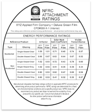
Look for the NFRC–certified attachment ratings energy-performance label, which helps consumers understand the contrast in energy performance of window films. An example of a window film energy performance label is shown on Figure 3-18.
Window Film Compliance
To receive window film credit, the following must be met:
1. The performance approach must be used.
2. Use only the alteration to existing building compliance method.
a. The NFRC window film energy performance label is required for each film; otherwise, use the Default Table 110.6-A and 110.6-B values.
b. Window films shall have a 15-year or longer warranty.
Figure 3-18: Window Film Energy Performance Label
Skylights can be either flush-mounted or curb-mounted into a roof system. To ensure water flows around them, skylights are often mounted on curbs set above the roof plane. These curbs, rising 6 to 12 inches above the roof, create additional heat loss surfaces.
3.3.4.1 Skylight Mandatory Measures
Skylights must meet all mandatory requirements for fenestration in §10-111, §110.6 and §110.7. Either the prescriptive or performance approach may be used.
When skylights are specified, the designer must show the skylit daylight zones on the building plans. There are mandatory requirements for lighting controls related to daylighting. See Section 3.3.3. Automatic daylighting controls are required when the installed power in the daylit zones of a room is greater than 120W. See Chapter 5 of this manual for a detailed discussion of the daylight zones.
3.3.4.2 Skylight Prescriptive Requirements
There are four aspects of the prescriptive envelope approach for skylights:
1. Maximum total area.
2. Maximum U-factor.
3. Maximum solar heat gain coefficient (SHGC).
4. Minimum visible transmittance (VT).
|
|
All Climate Zones | |||
|
Glass, Curb Mounted |
Glass, Deck-Mounted |
Plastic, Curb-Mounted | ||
|
Nonresidential |
U-factor |
0.58 |
0.46 |
0.88 |
|
SHGC |
0.25 |
0.25 |
NR | |
|
VT |
0.49 |
0.49 |
0.64 | |
|
Maximum SRR% |
5% | |||
|
High-Rise Residential |
U-factor |
0.58 |
0.46 |
0.88 |
|
SHGC |
0.25 |
0.25 |
NR | |
|
VT |
0.49 |
0.49 |
0.64 | |
|
Maximum SRR% |
5% | |||
Excerpt from Energy Standards Tables 140.3-B and 140.3-C, Skylight Roof Ratio, SRR
Skylight area is defined in Reference Joint Appendix JA1 as the area of the rough opening of a skylight. The area limit for skylights is 5 percent of the gross exterior roof area, called the skylight roof ratio (SRR). The limit increases to 10 percent for buildings with an atrium more than 55 ft high. The 55-ft height is the threshold at which the California Building Code requires a mechanical smoke-control system for atriums (CBC Sec. 909). This means that the 10 percent SRR is not allowed for atriums unless they also meet the smoke control requirement.
Site-built monumental or architectural skylights equipped with integral built-in or site-built curbs (not part of the roof construction) are often used for atrium roofs, malls, and other applications that need large skylights. In these cases, the skylight area is the surface area of the glazing and frame/curb, not the area of the rough-framed opening. Regardless of the geometry of the skylight (flat pyramid, bubble, barrel vault, or other three-dimensional shape), what matters is the anticipated heat exchanged through the glazing area. For special cases such as clerestory, rooftop monitor or tubular skylights, see Chapter 5.
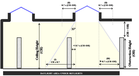
§140.3(c)4 requires that the skylight area be at least 3 percent of the floor area (not accounting for obstructions), or that the total of the skylight area multiplied by the area-weighted average visible transmittance of the skylights be at least 1.5 percent of the floor area (not accounting for obstructions). This assures that enough light reaches the skylit spaces. The visual transmittance option acknowledges that more skylight area is not needed for buildings with highly transmitting skylights. For example, if plastic skylights are installed with the prescriptive minimum transmittance of 0.64, the maximum ratio of skylight area to floor area within 0.7 times the ceiling height of skylights is 2.3 percent.
Figure 3-19: Skylight Area

The U-factor for skylights is an inclusive measurement of its heat losses, and includes heat losses through the glazing, the frame, and the integral curb (when one exists). If an NFRC rating does not exist, such as for projecting plastic skylights, the designer can use default fenestration U-factors found in Table 110.6-A of the Energy Standards.
For skylights, the U-factor criteria depend on whether the skylight glazing material is plastic or glass, and whether the skylight is curb-mounted, noting that plastic skylights are assumed to be mounted on a curb. These criteria are shown in Tables 140.3-B, C, and D. (Table 3-18)
Skylights are regulated for SHGC rather than RSHGC because skylights cannot have overhangs. The SHGC criteria vary with the SRR, and the criteria can be found in Tables 140.3-B, C, and D (Table 3-18). The designer can use default SHGC values in Table 110.6-B of the Energy Standards, or can use the Nonresidential Reference Appendix NA6 if all site-built fenestration (skylights and vertical fenestration) is less than 200 ft².
Skylights shall have an area-weighted average visible transmittance (VT) of no less than the value required by Tables 140.3-B, C, and D (Table 3-18). There are exceptions for chromogenic glazing.
E. Daylighting
Appropriately sized skylight systems can dramatically reduce the lighting energy consumption of a building when combined with appropriate daylighting controls. Daylighting control requirements under skylights are discussed in Chapter 5.
Mandatory Daylighting Controls
Electric lighting in skylight daylit zones shall meet the mandatory control requirements in §130.1(d). Obstructions are ignored for evaluating the architectural area served by skylights. For controlling lighting, consider the area shaded that is behind permanent obstructions that are greater than half the ceiling height. Those luminaires behind tall obstructions are not part of the skylit daylit area and not controlled by automatic daylighting controls.
Minimum Daylighting Prescriptive Requirements in Large Enclosed Spaces
Sizing is important; since too little skylight area has insufficient light available to turn off electric lighting; where too much skylight area, solar gains and heat losses through skylights negate the lighting savings by adding heating and cooling loads.
Figure 3-20: Present Value Savings of Skylight 50,000 ft² Warehouse in Climate Zone 12

Skylights and automatic daylighting controls are most cost-effective in large open spaces and are prescriptively required in enclosed spaces (rooms):
•Larger than 5,000 ft².
•Directly under a roof.
•Ceiling heights greater than 15 ft.
•Lighting power densities greater than 0.3 W/ft².
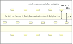
The Energy Standards require that at least 75 percent of the floor area be within one or more of the following:
1. A skylit daylit zone, an area in plain view that is directly under a skylight or within 0.7 times the average ceiling height in each direction from the edges of the rough opening of the skylight (see Figure 3-20), or
2. A primary sidelit daylit zone, an area in plain view that is directly adjacent to vertical glazing, one window head height deep into the area, and window width plus 0.5 times window head height wide on each side of the rough opening of the window based on §130.1(d).
Figure 3-20: Area Within 0.7 Times Ceiling Height of Rough
Opening of
Circular Skylight and Rectangular Skylight
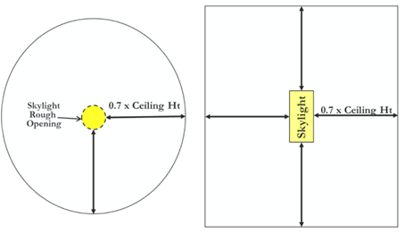
The shape of the skylit daylit zone will be similar in shape to the rough opening of the skylight (Figure 3-20).
Examples: If the skylight is circular, the area that is within a horizontal distance 0.7 times the average ceiling height from the edge of the rough opening, is also a circle, with the radius of the circle being the radius of the skylight + 0.7 x the ceiling height.
If the skylight is rectangular, the zone is rectangular, with the edges increased in each direction by 0.7 times the ceiling height.
Figure 3-21: Comparison of Skylit Area for Calculating Minimum
Skylit Area and
the Skylit Daylit Zone for Controlling Luminaires in
§130.1(d)
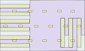
|
a) Entire space is within 0.7 x ceiling height of skylights for meeting minimum daylit area (§140.3(c)) |
b)Skylit daylit zone (§130.1(d)) for controlling luminaires is limited by racks blocking daylight |
The specifications for daylighting controls in §130.1(d) describe which luminaires must be controlled, and consider the daylight obstructing effects of tall racks, shelves, and partitions taller than one-half the distance from the floor to the bottom of the skylight when determining if daylight will reach a given space. As shown in Figure 3-21, it is considerably easier to calculate.
(a) The total floor area in the space within a horizontal distance of 0.7 times the average ceiling height from the edge of rough opening of skylights.
Versus
(b) The total floor area in the space within a horizontal distance of 0.7 times the average ceiling height from the edge of rough opening of skylights, minus any area on a plan beyond a permanent obstruction that is taller than the following: A permanent obstruction that is taller than one-half the distance from the floor to the bottom of the skylight.
(a) is required to be calculated to comply with minimum skylight area requirements of §140.3(c), and (b), is required to comply with the automatic daylighting control requirements of §130.1(d) (essentially, to ensure that daylighting controls are not installed where they would not be effective).
In §130.1(d), the skylit daylit areas are required to be drawn on the plans, and any general lighting luminaires that are in the daylit zones must be separately controlled by automatic daylighting controls. (See the daylighting requirements in Chapter 5 Lighting).
Two exemptions from §140.3(c) include:
1. Auditoriums, churches, museums and movie theaters due to the demanding lighting control needs.
2. Refrigerated warehouses to minimize heat gains.
Since skylights paired with daylighting controls can significantly reduce energy demands from lighting, they are mandatory on all nonresidential occupancies that meet the above criteria whether the space is conditioned or unconditioned. Further information can be found in Section 3.3.3.1.
For large buildings with high ceilings, skylighting 75 percent of the floor area can be achieved by evenly spacing skylights across the roof of the building. As a general rule, a space can be fully skylighted by having skylights spaced so that the edges of the skylights are not further than 1.4 times the ceiling height apart. For example, in a space having a ceiling height of 20 feet, the space can be fully skylighted if the edges of skylights are no more than 28 feet apart.
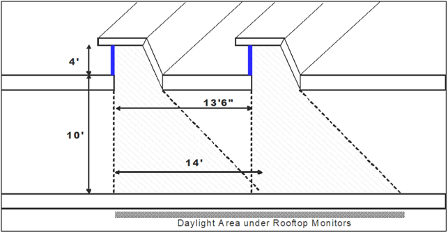
F. Rooftop Monitors
Rooftop monitors are considered vertical fenestration, and the daylight area next to them is the same as the daylit area next to other vertical fenestration. The daylit area is from the inward facing plane of the fenestration one window head height and in the direction parallel to the fenestration 0.5 window head heights on either side.
Figure 3-22: Daylight Area Under Rooftop Monitors (Primary Sidelit Daylit Zone)
G. Exceptions for Shading
Minimum daylighting requirements are exempted for spaces where permanent architectural features of the building, existing structures or natural objects block direct beam sunlight on at least half of the roof over the enclosed space for more than 1,500 daytime hours per year between 8 a.m. and 4 p.m. This can be documented to the local building official using a variety of tools including equipment that superimposes the sun path diagram on a photograph of the sky taken at the site, hand calculation tools such as the sun path calculator, and computer-aided design software tools that automate this calculation.
3.3.4.3 Ignoring Partitions and Shelves
The rationale for ignoring the presence of partitions for specifying minimum skylight area and spacing is that the design of the envelope may be developed before there is any knowledge of the location of the partial height partitions or shelves, as is often the case for core and shell buildings. Thus, the architectural daylit zone requirement of 75 percent of the space area indicates the possibility of the architectural space being mostly daylit. By not accounting for partial ceiling height partitions and racks, the Energy Standards are consistent in addressing architectural daylit areas, regardless of whether the design is core and the shell or a complete design development, including interior design. This approach does not require the addition of extra skylights or windows if racks and partial height partitions are added later.
Example 3-16
Question:
What is the maximum spacing and recommended range for skylights in a 40,000 ft2 warehouse with 30-foot-tall ceiling and a roof deck?
Answer:
From the definition of Skylit Daylit Zone in Section 130.1(d), the maximum spacing of skylights that will result in the space being fully skylit is:
Maximum skylight spacing = 1.4 x Ceiling Height + Skylight width
Spacing skylights closer together results in more lighting uniformity and thus better lighting quality, – but costs more as more skylights are needed. However, as a first approximation, one can space the skylights 1.4 times the ceiling height. For this example, skylights can be spaced 1.4 x 30 = 42 feet. In general, the design will also be dictated by the size of roof decking materials (such as 4’ by 8’ plywood decking) and the spacing of roof purlins so the edge of the skylights line up with roof purlins. For this example, staff assumes that roof deck material is 4’ by 8’ and skylights are spaced on 40-foot centers.
Each skylight is serving a 40-foot by 40-foot area of 1,600 sf. A standard skylight size for warehouses is
often 4’ by 8’ (so it displaces one piece of roof decking). The ratio of skylight area to daylit area is 2 percent (32/1600 = 0.02). Assuming this is a plastic skylight and it has a minimally compliant visible light transmittance of 0.64, the product of skylight transmittance and skylight area to daylit area ratio is
(0.64)(32/1,600) = 0.013 = 1.3%
This is a little less than the 2 percent rule of thumb described earlier for the product of skylight transmittance and skylight area to daylit area ratio. If one installed an 8 ft by 8 ft skylight (two 4 ft by 8 ft skylights) on a 40-foot spacing, it would yield a 2.6 percent product of skylight transmittance and skylight area to daylit area ratio and provide sufficient daylight. With 64 square feet of skylight area for each 1,600 square feet of roof area, the skylight-to-roof area ratio (SRR) is 4 percent, which is less than the maximum SRR of 5 percent allowed by Section 140.3(a) and thus complies with the maximum skylight requirement.
An alternate (and improved) approach would be to space 4 ft x 8 ft skylights closer together, which would provide more uniform daylight distribution in the space and could more closely approach the desired minimum VT skylight area product. A 32-foot center-to-center spacing of skylights results in (32 x 32) = 1,024 square feet of daylit area per skylight. By taking the product of the skylight VT and the skylight area and dividing by 0.02 (the desired ratio), it yields the approximate area the skylight should serve. In this case, with a VT of 0.65 and a skylight area of 32 square feet, each skylight should serve around:
(0.64 x 32 /0.02) = 1,024 sf.
For a minimally compliant 4 ft by 8 ft plastic skylight with a visible light transmittance of 0.65, the product of skylight transmittance and skylight area to daylit area ratio is:
(0.64)(32/1,024) = 0.020 = 2.0%
Energy savings can be improved than this rule of thumb approach by using a whole-building energy performance analysis tool that enhances the trade-offs among daylight, heat losses and gains, and electric lighting energy consumption.
3.3.4.4 Glazing Material and Diffusers
3. Skylights shall have a glazing material or diffuser that has a measured haze value greater than 90 percent, tested according to ASTM D1003 (notwithstanding its scope) or other test method approved by the Energy Commission.
For conditioned spaces the Energy Standards require the use of double-glazed skylights. When the skylights are above unconditioned spaces, there is no limitation placed on the maximum skylight area or the U-factor or SHGC. Regardless of whether the space is conditioned, the Energy Standards require that the skylights diffuse and bring in enough sunlight so that, when the electric lights are turned off, the occupants have relatively uniform daylight in the space. If the space is unconditioned, single-glazed skylights will comply with the code requirements as long as the glazing or diffuser material has a haze rating greater 90 percent and the visible transmittance meets the VT requirements in Table 140.3-B or C of the Energy Standards. Products that have such a rating include prismatic diffusers, laminated glass with diffusing interlayers, pigmented plastics, and so forth. This requirement assures that light is diffused over all sun angles. Any unconditioned space that later becomes conditioned must meet the new construction envelope requirements. Therefore, if the space may become conditioned in the future, it is recommended that the envelope meet the conditioned envelope thermal requirements.
Other methods that result in sufficient diffusion of light over the entire year would also be acceptable in lieu of using diffusing glazing. Acceptable alternatives are baffles or reflecting surfaces that ensure direct beam light is reflected off a diffuse surface before entering the space over all sun angles encountered during a year. This alternative method of diffusion would need to be documented by the designer and approved by the code authority in your jurisdiction.
Figure 3-23: Daylit Area Under Skylights
Certain design features and technologies have the capacity to increase the daylighting potential of spaces. Some of these design features and technologies may be used in conjunction with automatic daylighting controls to receive PAFs from Table 140.6-A, or as a performance compliance option (PCO) in the performance method.
A thorough daylighting analysis should be performed to ensure the avoidance of glare issues when including daylighting features in the design. An example where caution should be taken is specularly reflective (e.g. polished or mirror-finished) horizontal slats. These slats may redirect direct beam sunlight causing uncomfortable glare. This is not the only consideration when designing daylighting features. Daylighting analysis should be performed on a space-by-space, project-by-project basis.
Throughout all phases of the project, the envelope and lighting designers will need to coordinate closely to ensure that the requirements are met for their respective disciplines. Even if the envelope (e.g. horizontal slats) portion of the requirements meets all the envelope requirements, installing daylighting controls that do not meet the daylighting controls requirements will result in a loss of the PAF or PCO. Chapter 5, Section 5.5.1 gives guidance on the daylighting controls requirements.
3.3.5.1 Clerestory Fenestration
Clerestory windows may be used in conjunction with automatic daylighting controls to receive a prescriptive PAF. Clerestory windows increase the head height of windows and therefore increase the depth and width of the primary and secondary daylit zones for a space.
As with all vertical fenestration installed in a building, clerestory windows must meet the vertical fenestration requirements.
A. Qualifying Fenestration Area
Any portion of vertical fenestration area 8 feet or higher above the finished floor of a space is considered a clerestory window. Note that a rooftop monitor (see Figure 3-22) qualifies as a clerestory window.
B. Orientation
For the PAF, the clerestory windows must be installed on east-, west- or south-facing facades.
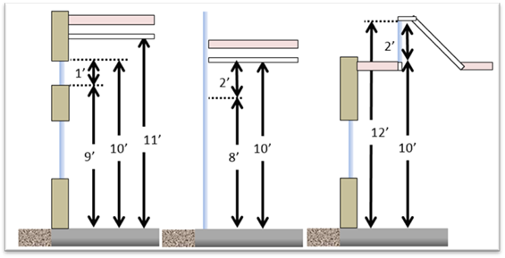
C. Head Height and Window Height
For the PAF, clerestory windows must have a head height at least 10 feet above the finished floor of the space onto which the clerestory window is installed. The clerestory window height must be at least 10 percent of its head height. Examples are given in Figure 3-24.
Figure 3-24: Prescriptive PAF Clerestory Window Examples
D. Shading
Blinds or shading may not be installed at the time of inspection. However, if blinds or shading are installed at the time of inspection, then the blinds or shading which covers the clerestory window must be shown to be controlled separately from shading serving other vertical fenestration.
3.3.5.2 Interior and Exterior Horizontal Slats
Horizontal slats on exterior or interior of windows may be used in conjunction with automatic daylighting controls to receive a prescriptive PAF or as a PCO in the performance method. Exterior horizontal slats may be preferable in a design to reduce solar gains whereas interior horizontal slats may be preferable considering wind loads, thermal bridging, passive solar heating, or vandalism.
A. Adjacency and Window-to-Wall Ratio (WWR)
For the PAF, horizontal slats must be installed adjacent to (in front or behind) vertical fenestration. They must also extend the entire height of the window, and the WWR must be between 20 percent and 30 percent. The horizontal slats must be mounted on windows on east- and west-facing facades.
B. Side-Shading
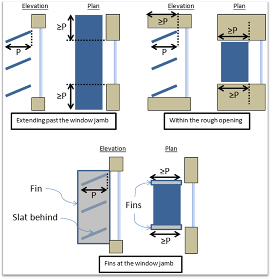
Horizontal slats must block direct beam sunlight at their side edges. At sharp horizontal angles to the window (i.e. high and low relative azimuths), direct beam sunlight still passes through horizontal slats if they are only as wide as the window. Similar to overhangs, slats must extend on either side of the window at least as far as their horizontal projection.
Alternatively, the horizontal slats can be located entirely within the reveal for the window or have fins on either side from top to bottom. Diagrams of qualifying side-shading configurations are given in Figure 3-25.
Figure 3-25 Qualifying Horizontal Side-Shading
C. Projection Factor
Horizontal slats must shade direct beam sunlight from above. They may be level or slope downwards when looking out the window (i.e. exterior horizontal slats slope downwards from fenestration while interior horizontal slats slope upwards from fenestration).
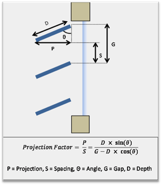
Projection factor is the ratio of the effective horizontal depth to the effective vertical spacing of a shading surface.
For the PAF, the projection factor must be at least 2.0 and no greater than 3.0. The projection factor is calculated per Equation 140.3-D. Horizontal slat angle, depth, gap and corresponding spacing and horizontal projection are illustrated in Figure 3-26. The spacing and horizontal projection must be documented in the construction documents.
Figure 3-27 Projection Factor for Horizontal Slats
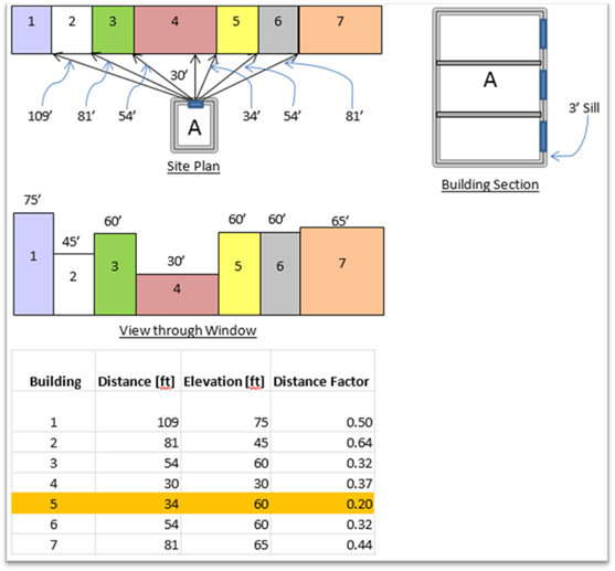
D. Distance Factor
Distance factor is calculated using the projection factor, the elevation of the window sill, and the distance and elevation of the top of obstructions within view of the window. To determine the lowest distance factor for the window, all obstructions within view of the window must be considered. This includes building self-shading from walls within view of the window. Distance factor is calculated using Equation 140.3-D. For the PAF, the distance factor must be at least 0.3. Example 3-17 shows how to calculate distance factor.
Note that for calculating distance factor, the shape of the obstruction is not accounted for. This is accurate for a situation where the relative heights of obstructions are similar, such as a street with an ordinance on height limit, but it actually may not be relevant if the obstruction does not cast much of a shadow (e.g. a radio tower on a hill).
In these cases, the project may instead demonstrate to the enforcement agency that the fenestration is shaded for less than a certain number of daytime hours between 8 am and 5 pm. For the PAF, the minimum number of shaded hours is 500. Section 3.3.3.2.2Q gives an example of how to demonstrate shaded hours.
Example 3-17
Question
Building “A” in the diagram below faces east and has a window on the first floor with a sill height of three feet. There are seven buildings within view of this window with the distances and elevations as given in the figures. Can the designer use horizontal slats with a projection factor of 3.0 on this window to receive a PAF?
Answer:
No. Building 5 is too close compared to its height.
Equation 140.3-D for distance factor is applied to each of the seven buildings within view of building A. For these buildings, the elevations are the same all along their flat rooftops. So, the objects which might not comply with the minimum distance factor requirement correspond to each of the buildings’ rooflines. If we examine the closest point for the rooflines, we will be assured that they will not shade as much or more than the horizontal slats are intended to. The closest point for these rooflines are the sides of the buildings to the side of building A’s view (namely, buildings 1-3 and 5-7) and the distance directly across for buildings in front of building A (i.e., building 4). In the case of building 5, this distance factor is
Distance Factor=D/(H_AS*Projection Factor)=34/((60-3)*3.0)=0.2<0.3 (Minimum Distance Factor)
This is lower than the minimum distance factor, so horizontal slats with a projection factor of 3.0 can’t be used for the PAF credit.
What can the designer do? The designer may select a lower projection factor or may choose to only use horizontal slats on the 2nd and higher floors of the building which have higher sill elevations.
E. Reflectance and Transmittance
The visible reflectance of horizontal slats must be tested as specified in ASTM E903. Certain coatings for horizontal slats have already been tested per ASTM E903 and can be researched to avoid re-testing. For the PAF, the visible reflectance must be at least 0.50.
If slats are opaque, then they do not require visible transmittance testing. But if they are not opaque, they must be tested as specified in ASTM E1175 and have a visible transmittance of 0.03 or less.
Horizontal slats must be permanently mounted and not adjustable by occupants or facilities personnel. Horizontal slats are intended to be fixed and unmoving. Venetian blinds do not qualify for the PAF or a performance compliance option. Fasteners such as bolts, welds, and rivets are examples of fasteners that may be used to meet this requirement as long as they impede the movement of the horizontal slats and the horizontal slat assembly as a whole.
G. Labeling
A factory installed label must be permanently affixed and prominently located on an attachment point of the device to the building envelope. This label spells out that removal of the horizontal slats will trigger re-submittal of compliance documentation to the enforcement agency. If the horizontal slat assembly is removed, the building owners will again need to prove that the building still meets the requirements of Title 24, Part 6 with the slats removed.
Specifically, the label must state:
“NOTICE: Removal of this device will require re-submittal of compliance documentation to the enforcement agency responsible for compliance with California Title 24, Part 6.”
3.3.5.3 Interior and Exterior Light Shelves
Interior light shelves combined with exterior light shelves on clerestory windows can be used in conjunction with automatic daylighting controls to receive a PAF. Light shelves block and redirect direct sun beam onto the ceiling of a space then reflect it downward into the space.
One pitfall of interior light shelves is the tendency for occupants to place objects on top of them, effectively using them as shelving. Thoughts should be put into the design of interior light shelves so as to discourage their use in this manner.
A. Exterior Light Shelf Exception and RHSGC
An exterior light shelf also acts as an overhang, blocking direct sun beam through any window area below the clerestory window (the “view window” area). Thus, it may take the overhang SHGC credit. If there is no view window area below the light shelf, then an exterior light shelf may still be installed but it is not required. Diagrams of qualifying interior and exterior light shelf configurations are given in Figure 3-27.
Figure 3-27 Qualifying Interior and Exterior Light Shelves Combinations
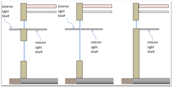
B. Clerestory
Light shelves must be installed adjacent to a clerestory window that meets the requirements discussed in the Clerestory Fenestration section. In addition, interior light shelves depend on a ceiling to reflect daylight. So, the clerestory window’s head must be no greater than one foot below a finished ceiling.
C. Window-to-Wall Ratio (WWR) and Orientation
For the PAF, the WWR must be greater than 30 percent. The light shelves must be mounted on windows on south-facing facades.
D. Side-Shading
Light shelves must block direct beam sunlight at their side edges. At sharp horizontal angles to the window (i.e. high and low relative azimuths), direct beam sunlight still passes through horizontal slats if they are only as wide as the window. Similar to overhangs, light shelves must extend on either side of the window at least as far as their horizontal projection. An example of a qualifying side-shading configuration is given in Figure 3-28.
Figure 3-28 Qualifying Light Shelf Side-Shading Example
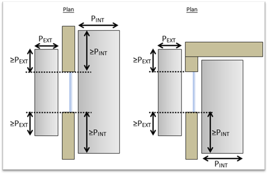
E. Projection Factor
Light shelves must shade direct beam sunlight from above. They may be level or slope downwards when looking out the window (i.e. exterior light shelves slope downwards from fenestration while interior light shelves slope upwards from fenestration). The slopes of interior light shelves should not be too steeply or they may block the daylight reflected off of the ceiling, thus reducing the daylighting benefits.
Projection factor is the ratio of the effective horizontal depth to effective vertical spacing of a shading surface. The projection factor is calculated per Equation 140.3-D. For a PAF, the interior light shelf projection factor must be at least 1.0 and not greater than 2.0. The exterior light shelf projection factor must be at least 0.25 and not greater than 1.25.
Light shelf angle, depth, gap, and corresponding spacing and horizontal projection are illustrated in Figure 3-29. The light shelf spacing and horizontal projections must be documented in the construction documents.
Figure 3-29 Projection Factor for Light Shelves
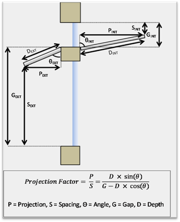
F. Distance Factor
The requirements and procedures for distance factor are the same as those for horizontal slats as given in the Horizontal Slats section. For the light shelf PAF, the minimum shaded hours are 750.
G. Reflectance
The visible reflectance of the top surface of light shelves must be tested as specified in ASTM E903. If the exterior light shelf is greater than two feet below the clerestory sill, then the top surface of the exterior light shelf needs not be reflective. Certain coatings for light shelves have already been tested per ASTM E903 and can be researched to avoid re-testing.
For the PAF, the visible reflectance must be at least 0.50.