5.2
Project Data
5.2.1
General Information
|
Project Name |
|
Applicability |
All projects |
|
Definition |
Name used for the project, if one is
applicable |
|
Units |
Up to 50 alphanumeric characters |
|
Input Restrictions |
Input is optional for the proposed design |
|
Standard Design |
Not applicable |
|
Building Location |
|
Applicability |
All projects |
|
Definition |
Street address, city, state, and zip code |
|
Units |
Up to 50 alphanumeric characters on each of two
lines |
|
Input Restrictions |
Input is optional for the proposed design |
|
Standard Design |
Not applicable |
|
Project Owner |
|
Applicability |
All projects |
|
Definition |
Owner(s) of the project or individual or organization
for whom the building permit is sought; should include name, title,
organization, email, and phone number |
|
Units |
Up to 50 alphanumeric characters |
|
Input Restrictions |
Input is optional for the proposed design |
|
Standard Design |
Not applicable |
|
Envelope Designer |
|
Applicability |
All projects |
|
Definition |
Person responsible for the building design; information
should include name, title, organization, email, and phone
number |
|
Units |
Up to 50 alphanumeric characters |
|
Input Restrictions |
Input is optional for the proposed design |
|
Standard Design |
Not applicable |
|
Mechanical Designer |
|
Applicability |
All projects |
|
Definition |
Person responsible for the mechanical design;
information should include name, title, organization, email, and phone
number |
|
Units |
Up to 50 alphanumeric characters |
|
Input Restrictions |
Input is optional for the proposed design |
|
Standard Design |
Not applicable |
|
Lighting Designer |
|
Applicability |
All projects |
|
Definition |
Person responsible for the lighting design; information
should include name, title, organization, email, and phone
number |
|
Units |
Up to 50 alphanumeric characters |
|
Input Restrictions |
Input is optional for the proposed design |
|
Standard Design |
Not applicable |
|
Documentation Author
|
|
Applicability |
All projects |
|
Definition |
Person responsible for inputting building information
and performing the compliance analysis; information should include name,
title, organization, email, and phone number |
|
Units |
Up to 50 alphanumeric characters |
|
Input Restrictions |
Input is optional for the proposed design |
|
Standard Design |
Not applicable |
|
Date |
|
Applicability |
All projects |
|
Definition |
Date of completion of the compliance analysis or the
date of its most-recent revision |
|
Units |
Date format |
|
Input Restrictions |
Input is optional for the proposed design |
|
Standard Design |
Not applicable |
|
Compliance Type |
|
Applicability |
All projects |
|
Definition |
Type of compliance project (new construction, partial
compliance or additions and alterations) |
|
Units |
List:
NewComplete: new construction project
NewEnvelope: new construction, partial
compliance with envelope
NewEnvelopeAndLighting: new construction,
partial compliance with envelope and lighting
NewEnvelopeAndPartialLighting: new construction,
partial compliance with envelope and lighting compliance for some
spaces
NewEnvelopeAndMechanical: new construction,
partial compliance with mechanical and envelope only
NewMechanical: new construction, partial
compliance with mechanical. This is the complement of a partial compliance
with envelope and lighting, which should have already been performed.
NewMechanicalAndLighting: new construction,
partial compliance with mechanical and lighting only. The building should
have already passed an Envelope Only partial compliance.
NewMechanicalAndPartialLighting: new
construction, partial compliance with mechanical and lighting compliance
for some spaces. The building should have already passed an Envelope Only
partial compliance.
ExistingAlteration: alteration project
ExistingAdditionAndAlteration: project with both
additions and alterations
AdditionComplete: an addition modeled alone
AdditionEnvelope: an existing building with
partial envelope compliance for a new addition
AdditionEnvelopeAndLighting: an existing
building with partial envelope and lighting compliance for a new
addition
AdditionEnvelopeAndPartialLighting: an addition
to an existing building that includes the building envelope and
lighting for some of the spaces. For the spaces with lighting defined in
the proposed design, the space function type must be defined as well. For
undefined spaces, the lighting status is “future” and both the proposed
design and standard design are set to match the prescriptive lighting
power limits.
AdditionEnvelopeAndMechanical: an addition
modeled with as-designed envelope and mechanical components, but the
interior lighting design has not yet been defined. For this option,
interior lighting must comply prescriptively.
AdditionMechanical: an addition modeled with the
as-designed mechanical system, including any plant, system or zone level equipment, as
well as ventilation. For this option, all envelope and lighting components
are modeled as defined by the user in both the proposed design and
standard designs.
AdditionMechanicalAndLighting: an addition
modeled with as designed mechanical and lighting equipment. In this
design, all building envelope components in the standard design are set to
match those in the proposed design, since the envelope is assumed to have
complied via a separate permit.
AdditionMechanicalAndPartialLighting: an
addition modeled with as designed mechanical equipment and with lighting
systems defined for part of the building. This model is the complement to the
AdditionEnvelopeAndParitalLighting compliance option,
since Envelope and lighting compliance for the spaces not included in this
compliance permit are assumed to have already been modeled (and
permitted). |
|
Input Restrictions |
As designed |
|
Standard Design |
Same as proposed |
5.2.2
Existing Building Classification
|
Existing Building Number of Stories |
|
Applicability |
Additions and alterations |
|
Definition |
Total number of stories of the building
(For information and reporting purposes only) |
|
Units |
Integer |
|
Input Restrictions |
As designed |
|
Standard Design |
Not applicable |
|
Existing Buildings |
Same as the Proposed Design |
|
Existing Building Floor Area |
|
Applicability |
Additions and alterations |
|
Definition |
Total floor area of an existing building, including any
additions, if present
(For information and reporting purposes only) |
|
Units |
ft2 |
|
Input Restrictions |
As designed |
|
Standard Design |
Not applicable |
|
Existing Buildings |
Not applicable |
5.2.3
Partial Compliance Model Input Classification
Earlier sections of this reference
manual have
described the available partial compliance scenarios. The compliance software that
supports these scenarios must define the inputs for both the proposed design and
the standard design for unpermitted portions of the building.
1)
Envelope Only:
The user specifies the building envelope and all spaces, space types, and thermal
zones in the building. The standard design rules are applied to the envelope
components. For all lighting and HVAC inputs, the proposed design values are
prescribed and follow the rules for the standard design, including modeling the
same HVAC systems determined using the new construction HVAC system map in Section
5.1.2.
2)
Envelope and Lighting Only: The user specifies the building envelope, spaces,
space types, thermal zones and all lighting, and any daylighting, where present.
For all HVAC inputs, the proposed design values are prescribed and follow the
rules for the standard design, including modeling the same HVAC systems
determined using the new construction HVAC system map in Section 5.1.2.
3)
Envelope and Mechanical Only: This compliance option assumes
that the building will use separately permitted prescriptive lighting
compliance. The user specifies the building envelope, spaces, space types,
thermal zones, and mechanical systems in the building. For all lighting inputs,
the proposed design values are prescribed and follow the rules for the standard
design.
4)
Envelope and Partial Lighting Only: This compliance option is used for projects
where the building envelope is defined, and where the lighting in some of the
spaces is defined. The user specifies the building envelope, all spaces, space
types, thermal zones, and lighting for spaces with lighting systems defined, and
any daylighting, where present. For all HVAC inputs, the proposed design values
are prescribed and follow the rules for the standard design, including modeling
the same HVAC systems determined using the new construction HVAC system map in
Section
5.1.2.
5)
Mechanical Only: This compliance option assumes that the building has already
been permitted for envelope and lighting. The envelope and lighting systems for
both the proposed design and the standard design are modeled as designed. (For
example, if the building vertical fenestration
area exceeds prescriptive WWR limits, the limits are NOT applied to the standard
design. Instead, the actual vertical fenestration area is used.) The
mechanical systems of the proposed model are described as-designed, and the new construction rules
and system map are applied to the HVAC system of the standard design.
6)
Mechanical and Lighting Only: This compliance option assumes that the building
has already been permitted for envelope compliance. All spaces and space types
must be defined by the user, and all envelope components for the proposed design
are “as designed” (must be defined by the user). The standard design lighting
and HVAC components are set to match the standard design.
7)
Mechanical and Partial Lighting Compliance: This compliance option assumes that
the building has already been permitted for Envelope and Partial Lighting
compliance (option 3 above). The envelope components, spaces and space types,
and permitted lighting spaces are entered as designed for the proposed design
and, for these components, the standard design is set to be the same as the
proposed. For the other components as part of the permit application, the
mechanical systems and new lighting systems are entered by the user for the
proposed design as designed, and the standard design components for the
mechanical (HVAC) system and new lighting systems are defined by the new
construction standard design rules.
8)
Envelope and Partial Mechanical: For projects where mechanical systems are not
defined for all thermal zones. When the “HVAC is Unknown” checkbox is enabled at
the thermal zone, the proposed mechanical system for that zone will be defaulted
to match the standard design. Possible uses for this compliance option include
“core and shell” projects and existing/addition/alteration projects with unknown
existing mechanical equipment.
Building descriptors with inputs
for both the proposed design and standard design that are restricted to
prescribed values (for example, equipment performance curves) follow the same
rules for prescribed values for any of the partial compliance projects listed above.
5.2.4
Building Model Classification
|
Space Classification Type |
|
Applicability |
All projects |
|
Definition |
One of two available classification methods for
identifying the function of the building or the functions of
spaces within the building, which in turn determine energy-related
requirements for the standard design. Appendix 5.4A lists the building
classifications that are available under the area category method.
The Area Category method uses a separate space
classification for each space in the building according to its
function.
The Tailored Lighting method allows
specification of function-specific illuminance level categories
and space geometry to assign allowed lighting power, following section
140.6 of the Standards. |
|
Units |
List (See Appendix 5.4) |
|
Input Restrictions |
As designed |
|
Standard Design |
Same as proposed |
5.2.5
Geographic and Climate Data
The following data needs to be
specified or derived in some manner. Software developers may use any acceptable
method to determine the data. For California, city, state, and county are
required to determine climate data from the available data in Reference Appendix
JA2.
|
Zip Code |
|
Applicability |
All projects |
|
Definition |
California postal designation |
|
Units |
List (see Appendix 5.4) |
|
Input Restrictions |
None |
|
Standard Design |
Not applicable |
|
Latitude |
|
Applicability |
All projects |
|
Definition |
The latitude of the project site |
|
Units |
Degrees (°) |
|
Input Restrictions |
Not a User Input |
|
Standard Design |
Latitude of representative city from Reference Appendix
JA2 |
|
Longitude |
|
Applicability |
All projects |
|
Definition |
The longitude of the project site |
|
Units |
Degrees (°) |
|
Input Restrictions |
Not a User Input |
|
Standard Design |
Longitude of representative city from Reference
Appendix JA2 |
|
Elevation |
|
Applicability |
All projects |
|
Definition |
The height of the building site above sea
level |
|
Units |
Feet (ft) |
|
Input Restrictions |
None |
|
Standard Design |
Elevation of representative city from Reference
Appendix JA2 |
|
California Climate Zone |
|
Applicability |
All projects |
|
Definition |
One of the 16 California climate zones |
|
Units |
List (see Reference Appendices
JA2) |
|
Input Restrictions |
None |
|
Standard Design |
Same as proposed |
|
City |
|
Applicability |
All projects |
|
Definition |
The city where the project is located |
|
Units |
Alphanumeric string |
|
Input Restrictions |
None |
|
Standard Design |
Representative city from Reference Appendix JA2 |
|
Design Day Data |
|
Applicability |
All projects |
|
Definition |
A data structure indicating design day information used
for the sizing of the proposed system. Note: this information may not necessarily match
the information used in the annual compliance simulation. |
|
Units |
Data structure: contains the following:
Design DB (0.5%), mean coincident wet-bulb, daily
range, day of year |
|
Input Restrictions |
The design day information is taken from one of the 86
pre-defined California weather files, for the location within the same
climate zone that is closest to the proposed building’s location. (This is
not input by the user.) |
|
Standard Design |
Not applicable |
|
Weather
File |
|
Applicability |
All
projects |
|
Definition |
The
hourly (i.e., 8,760 hour per year) weather data to be used in performing
the building energy simulations. Weather data must include outside
dry-bulb temperature, outside wet-bulb temperature, atmospheric pressure,
wind speed, wind direction, cloud amount, cloud type (or total horizontal
solar and total direct normal solar), clearness number, ground
temperature, humidity ratio, density of air, and specific enthalpy. |
|
Units |
Data
file |
|
Input
Restrictions |
The
weather file selected shall be in the same climate zone as the proposed
design. If multiple weather files exist for one climate zone then the
weather file closest in distance to the proposed design and in the same
climate zone shall be used. |
|
Standard
Design |
Weather
data shall be the same for both the proposed design and standard
design. |
|
Ground Reflectance |
|
Applicability |
All
Projects |
|
Definition |
Ground
reflectance affects daylighting calculations and solar gain. The
reflectance can be specified as a constant for the entire period of the
energy simulation or it may be scheduled, which can account for snow cover
in the winter. |
|
Units |
Data
structure: schedule, fraction |
|
Input
Restrictions |
Prescribed. The weather
file determines the ground reflectance. The ground reflectance shall be
set to 0.2 when the snow depth is 0 or undefined, and set to 0.6 when the
snow depth is greater than 0. |
|
Standard
Design |
Same as
proposed |
|
Local Terrain |
|
Applicability |
All projects |
|
Definition |
An indication of how the local terrain shields the
building from the prevailing wind. Estimates of this effect are provided
in the ASHRAE
Handbook of Fundamentals. |
|
Units |
List: the list shall contain only the following
choices:
|
Description |
Exponent (α) |
Boundary layer thickness, δ (m) |
|
Flat, open country |
0.14 |
270 |
|
Rough, wooded country, Suburbs |
0.22 |
370 |
|
Towns and cities |
0.33 |
460 |
|
Ocean |
0.10 |
210 |
|
Urban, industrial, forest |
0.22 |
370 |
The exponent and boundary layer are used in the
following equation to adjust the local wind speed:
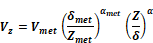
Where:
Z= altitude, height above ground (m)
Vz = wind speed at altitude
Z(m/s)
a = wind
speed profile exponent at the site
δ = wind speed profile boundary layer thickness at the
site (m)
Zmet = height above ground of the
wind speed sensor at the meteorological station (m)
Vmet = wind speed measured at the
meteorological station (m/s)
amet = wind speed profile
exponent at the meteorological station
δmet = wind speed profile boundary layer
thickness at the meteorological station. (m)
The wind speed profile coefficients; a, δ, ametand δmet are
variables that depend on the roughness characteristics of the surrounding
terrain. Typical values for a
and δ are shown in the table above. |
|
Input Restrictions |
Weather data should be representative of the long term
conditions at the site |
|
Standard Design |
The standard design terrain should be equal to the
proposed design |
5.2.6
Site Characteristics
|
Shading of Building Site |
|
Applicability |
All projects |
|
Definition |
Shading of building fenestration, roofs, or walls by
surrounding terrain, vegetation, and the building itself |
|
Units |
Data structure |
|
Input Restrictions |
The default and fixed value is for the site to be
unshaded. External shading from other buildings or other objects is not
modeled for Title 24 compliance in the ACM. Building self-shading is
accounted for using the detailed geometry method. |
|
Standard Design |
The proposed design and standard design are modeled
with identical assumptions regarding shading of the building
site. |
|
Site Fuel Source |
|
Applicability |
All projects |
|
Definition |
The fuel source that is available at the site for water
heating, space heating or other fuel purposes. For most buildings
connected to a utility service, this will be natural gas. |
|
Units |
List |
|
Input Restrictions |
The following choices are available:
Natural Gas
Propane |
|
Standard Design |
Natural gas |
5.2.7
Calendar
|
Year
for Analysis |
|
Applicability |
All
projects |
|
Definition |
The calendar year to be
used for the annual energy simulations. This input determines the
correspondence between days of the week, and the days on which weather
events on the weather tape occur and has no other impact. |
|
Units |
List:
choose a year (other than a leap year) |
|
Input
Restrictions |
Use year
2009 |
|
Standard
Design |
Same
calendar year as the proposed design |
|
Schedule of Holidays |
|
Applicability |
All projects |
|
Definition |
A list of dates on which holidays are observed and on
which holiday schedules are used in the simulations |
|
Units |
Data structure |
|
Input Restrictions |
The following ten holidays represent the prescribed
set. When a holiday falls on a Saturday, the holiday is observed on the
Friday preceding the Saturday. If the holiday falls on a Sunday, the
holiday is observed on the following Monday.
New Year’s Day
January 1
Martin Luther King Day Third Monday in January
Presidents
Day
Third Monday in February
Memorial
Day
Last Monday in May
Independence
Day
July 4
Labor
Day
First Monday in September
Columbus
Day
Second Monday in October
Veterans
Day
November 11
Thanksgiving
Day
Fourth Thursday in November
Christmas
Day
December 25 |
|
Standard Design |
The standard design shall observe the same holidays
specified for the proposed design. |