This chapter specifies, for each building descriptor, the rules that apply to the proposed design and to the standard design.
Building descriptors provide information about the proposed design and the standard design. In this chapter, the building descriptors are discussed in the generic terms of engineering drawings and specifications. By using generic building descriptors, this manual avoids bias toward one particular energy simulation engine. The building descriptors in this chapter are compatible with commonly used simulation software.
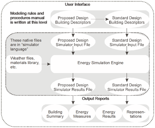
Each energy simulation program has a unique way of accepting building information. EnergyPlus uses a comma delimited data file called an IDF file. DOE-2 uses BDL (building design language) to accept information. It is the responsibility of the compliance software to translate the generic terms used in this chapter into the “native language” of the simulation program. Figure 7 illustrates the flow of information.
Figure 7: Information Flow
Source: NORESCO for California Energy Commission
The HVAC system in the standard design depends on the primary building activity, the size of the building, and the number of floors. Details about these systems are provided in subsequent sections.
Many of the building descriptors have a one-to-one relationship between the proposed design and the standard design; for example, every wall in the proposed design has a corresponding wall in the standard design. For HVAC systems, however, this one-to-one relationship generally does not hold. The HVAC system serving the proposed design and the standard design may be completely different, each with different components.
The HVAC system in the standard design shall be selected from Table 2: HVAC System Map, and be based on building type, number of floors, conditioned floor area, and heating source. Moreover, the selected system shall conform to the descriptions in Table 5: System Descriptions.
For systems 1, 2, 3, 7, 10, and 11, each thermal zone shall be modeled with a respective HVAC system. For systems 5, 6, and 9, each floor shall be modeled with a separate HVAC system. Floors with identical thermal zones and occupancies can be grouped for modeling. The standard design heating source is natural gas.
|
Building Type |
Standard Design |
|
Residential or hotel/motel guestrooms in a building with seven or fewer floors above grade |
System 1 - SZAC |
|
Residential or hotel/motel guestrooms in a building with eight or more floors above grade |
System 2 - FPFC |
|
Retail building 2 floors or fewer |
System 7 - SZVAV* |
|
Warehouse and light manufacturing space types (per the Appendix 5.4A Schedule column) that do not include cooling in the proposed design |
System 9 - HEATVENT |
|
Covered process |
|
|
Healthcare Facilities |
Same as the Proposed Design |
|
All other space types |
See
Table 3:
Nonresidential Spaces (Not Including Covered Processes) |
|
Building Area |
Floors |
Standard Design |
Description |
|
< 25,000 ft2 |
≤ 3 floors |
System 7 - SZVAV* |
Single Zone VAV |
|
4 or 5 floors |
System 5 - PVAV |
Packaged VAV Unit | |
|
> 5 floors |
System 6 - VAVS |
Built-up VAV Unit | |
|
25,000 ft2–150,000 ft2 |
≤ 5 floors |
System 5 - PVAV |
Packaged VAV Unit |
|
> 5 floors |
System 6 - VAVS |
Built-up VAV Unit | |
|
>150,000 ft2 |
Any |
System 6 - VAVS |
Built-up VAV Unit |
* Single zone VAV (SZVAV) systems serving all space types except laboratories shall have a minimum fan speed ratio of 0.5 if the standard design total cooling capacity ≥ 65 kBtu/h, and a minimum fan speed ratio of 1 (constant volume) for a standard design total cooling capacity less than 65 kBtu/hr. SZVAV systems serving laboratory spaces shall have a minimum fan speed ratio of 0.2 for all standard design cooling capacities. SZVAV systems shall have an integrated economizer if the standard design cooling capacity exceeds 54 kBtu/h.
Retail building Standard Design rules shall apply to zones on floors (building stories) whose predominant space type is retail.
|
Building Type or Space Type |
Floors |
Standard Design System |
|
Total computer room design cooling load is over 3,000,000 Btu/h Note: if the user chooses computer room for the space type and enters a receptacle load less than 20 W/ft2, then the proposed and standard design shall use a receptacle load of 20 W/ft2. |
Any |
System 10 – CRAH Unit |
|
Computer rooms that do not meet the conditions for System 10, CRAH |
Any |
System 11 – CRAC Unit |
|
Laboratory Space |
Any |
System 12 – LAB |
|
Restaurant Kitchen |
Any |
System 13 – KITCH |
|
System Type |
Description |
Detail |
|
System 1 – SZAC |
Residential Air Conditioner |
Single zone system with constant volume fan, no economizer, DX cooling and furnace |
|
System 2 – FPFC |
Four-Pipe Fan Coil |
Central plant with terminal units with hot water and chilled water coils, with separate ventilation source |
|
System 3 – SZAC |
Packaged Single Zone |
Single-zone constant volume DX unit with gas heating |
|
System 4 – RESERVED |
|
|
|
System 5 – PVAV |
Packaged VAV Unit |
VAV reheat system; packaged variable volume DX unit with gas heating and with hot water reheat terminal units |
|
System 6 – VAVS |
Built-up VAV Unit |
Variable volume system with chilled water and hot water coils, water-cooled chiller, tower and central boiler |
|
System 7 – SZVAV |
Packaged Single-Zone VAV Unit |
Single-zone variable volume DX unit with variable-speed drive and gas heating |
|
System 8 – RESERVED |
|
|
|
System 9 – HEATVENT |
Heating and Ventilation Only |
Gas heating and ventilation |
|
System 10 – CRAH |
Computer Room Air Handler |
Built-up variable volume unit with chilled water, no heating |
|
System 11 – CRAC |
Computer Room Air Conditioner |
Packaged variable volume DX unit with no heating |
|
System 12 – LAB |
Laboratory HVAC System |
Laboratory spaces in a building having a total laboratory design maximum exhaust rate of 15,000 cfm or less use Table 3, Nonresidential System Map.
Laboratory spaces in a building with building floor area < 150,000 ft2: System 5 – PVAV
Laboratory spaces in a building with building floor Area ≥ 150,000 ft2: System 6 – VAVS |
|
System 13 – KITCH |
Kitchen HVAC System |
Dedicated single-zone makeup air unit (MAU) with dedicated exhaust fan. If the building is VAVS per Table 3, the cooling source is chilled water and the heating source is hot water. Otherwise, cooling source is DX and heating source is a gas furnace. |
Residential (24-hour) occupancies in mixed-use buildings are served by separate standard design systems than nonresidential space types. Also, spaces containing covered processes are served by dedicated standard design systems separate from systems serving other nonresidential space types. Examples include residential spaces located over retail and other similar conditions. For example, a 100,000 ft2 building that has retail and restaurant on floor 1, offices on floors 2, 3, and 4, a 20-ton computer room on each office floor, and residential on floors 5, 6, and 7 would have the following systems in the standard design:
•A KITCH serving the restaurant
•Retail spaces follow the system map, since the building has more than 2 stories
•A VAVS serving all office spaces
•Separate CRAC systems serving each computer room
•Separate FPFC systems serving each residential space
The standard design building shall have only one central chilled or hot water plant, so if there are multiple systems that incorporate a plant (for example, CRAH and VAVS), then a single plant shall serve all plant loads.
5.1.2.1 Additions and Alterations System Modification
For additions and alterations projects, the standard design building shall follow the same rules as the HVAC system map above, except that the building that will follow the logic of the system map rules may be the modeled building (the addition or alteration alone, or the addition or alteration and a portion of the existing building), or the entire building (the entire existing building, plus an addition, if present).
The decision on the existing building basis for applying the system map rules is:
The following rules apply to any building that has both heating and cooling systems.
1. Plant: If the change in plant cooling capacity exceeds 50 percent of the existing total cooling capacity of all cooling systems, the system map is based on the entire building characteristics. (See Section 5.2.2.)
2. Airside System: If the change in cooling capacity of the airside system (for example, air handling units, DX packaged units) of all cooling sources other than chilled water exceeds 50 percent of the existing rated cooling capacity for the building, then the HVAC system map is based on the entire building characteristics. Also, if the combined net cooling capacity of all altered airside systems exceeds 90 percent of the building cooling capacity, then the HVAC system map is based on the entire building characteristics.
3. Zone Level: If the change in the cooling capacity of the zonal systems (for example, SZAC units, FPFC units) exceeds 50 percent of the rated total cooling capacity of all zonal systems in the existing building, then the HVAC system map is based on the entire existing building characteristics. Also, if the combined net cooling capacity of all altered zonal systems exceeds 90 percent of the building cooling capacity, then the HVAC system map is based on the entire building characteristics.
4. If none of these three conditions apply, then the HVAC system map is based on the building characteristics of the modeled building for additions and alterations compliance, which may be just a portion of the entire building.
Since some additions and alterations projects will trigger the HVAC system map for the standard design, the user must enter a minimum set of building characteristics for the entire building (existing plus any addition); existing building floor area and number of stories must be entered.
Heating-Only System Modification
The following rules apply to any building that has only heating-only systems.
1. Plant: If the change in plant heating capacity exceeds 50 percent of the existing total space heating capacity of all heating systems, the system map is based on the entire building characteristics.
2. Airside System: If the change in heating capacity of the airside system (unitary DX equipment, heat pumps, for example) of all heating sources other than heating hot water exceeds 50 percent of the existing rated cooling capacity for the building, then the HVAC system map is based on the entire building characteristics. Also, if the combined net heating capacity of all altered airside systems exceeds 90 percent of the building heating capacity, then the HVAC system map is based on the entire building characteristics.
3. Zone Level: If the change in the heating capacity of the zonal systems (SZAC units, for example), exceeds 50 percent of the rated total heating capacity of all zonal systems in the existing building, then the HVAC system map is based on the entire existing building characteristics. Also, if the combined net cooling capacity of all altered zonal systems exceeds 90 percent of the building cooling capacity, then the HVAC system map is based on the entire building characteristics.
4. If none of these three conditions above apply, then the HVAC system map is based on the building characteristics of the modeled building for additions and alterations compliance, which may be just a portion of the entire building.
Since some additions and alterations projects will trigger the HVAC system map for the standard design, the user must enter a minimum set of building characteristics for the entire building (existing plus any addition): existing building floor area and number of stories must be entered.
Building descriptors are grouped under objects or building components. A wall or exterior surface (an object) would have multiple building descriptors dealing with the geometry, thermal performance, and so forth. Each building descriptor contains the following pieces of information:
|
Building Descriptor Title | |
|
Applicability |
Information on when the building descriptor applies to the proposed design |
|
Definition |
A definition for the building descriptor |
|
Units |
The units that are used to prescribe the building descriptor; A “List” indicates that a fixed set of choices applies and the user shall be allowed to enter only one of the values in the list |
|
Input Restrictions |
Any restrictions on information that may be entered for the proposed design |
|
Standard Design |
This defines the value for the “standard design” or baseline building applied for this building descriptor. A value of “same as proposed” indicates that the building descriptor is neutral, i.e., the value is set to match the proposed design value. In many cases, the value may be fixed or may be determined from a table lookup. In some cases, the input may not be applicable. For example, heat recovery effectiveness is not applicable because the standard design (baseline building) does not have heat recovery. |
|
Standard Design: Existing Buildings |
Standard design for existing buildings if different than new buildings. |
Compliance projects containing additions and/or alterations require that the user designate each building component (envelope construction assemblies and fenestration, lighting, HVAC, and water heating) as either new, altered, or existing. Many of the building descriptors in Chapter 5 of this manual do not have explicit definitions for the standard design when the project is an addition and/or alterations project. For these terms, the standard design rules for existing, altered components follow the same rule as the standard design rule for new construction.
For example, the receptacle loads are prescribed for both the proposed design building and standard design building for a new construction compliance project. For additions or alterations to an existing building, since the rules are not explicitly defined in the building descriptor in Section 5.3.3, the same rules apply to the proposed design and standard design for the additions or alterations compliance project.
Building descriptors that are prescribed for the proposed and standard design models for new construction projects are also prescribed for the proposed and standard design models for additions and alterations projects.
For additions and alterations projects, there are three modeling approaches that can be taken when modeling the existing building:
1. Model the addition or altered portion alone. For this option, the addition or alteration is modeled as a stand-alone building, and the boundary or interface between the addition and/or alteration and the preexisting building is modeled as an adiabatic partition (an adiabatic wall, ceiling, roof or floor).
2. Model the entire existing building and any additions and alterations. For this option, the existing, unaltered components of the building would be modeled “as designed” (as specified by the user), with the standard design components modeled the same as the proposed design.
3. Model part of the existing building and any additions and alterations. For this option, all components of the existing, unaltered building (HVAC, lighting, envelope, spaces) would have to be distinguished from the components that are added and altered. The existing building components would be modeled “as designed” (as specified by the user), with the standard design components modeled the same as the proposed design. Added or altered building components would follow the rules for additions and alterations.
When either Option 1 or Option 3 is used, the adiabatic partitions shall not be considered as part of gross exterior wall area or gross exterior roof area for the window/wall ratio (WWR) and skylight/roof ratio (SRR) calculations.