5.4 Space
Uses
Each thermal zone discussed above
may be subdivided into spaces. This section presents the building descriptors that relate to
the space uses. Space uses and the defaults associated with them are listed in Appendix
5.4A. Every thermal zone shall have at least one space, as defined in this
section. Daylit spaces should generally be separately defined by space type
and/or orientation.
5.4.1
General Information
|
Space Function Type |
|
Applicability |
All projects |
|
Definition |
The space function type that defines occupancy,
internal load, and other characteristics, as indicated in Appendix
5.4A.
If lighting compliance is not performed, use either approach
but actual LPDs cannot be entered for the spaces; the LPDs of the building match
the standard design.
The allowed space function types in area category are
available from Appendix 5.4A. The building or space type determines the
following standard design inputs:
Number of occupants (occupant density)
Equipment
power density
Lighting power density
Hot water load
Schedules (from Appendix 5.4B) |
|
Units |
List |
|
Input Restrictions |
Only selections shown in Appendix 5.4A may be used.
For unconditioned spaces, the user must enter
“unconditioned” as the occupancy and ventilation; internal loads and uses
are set to zero. Compliance software shall require the user to identify if
lighting compliance is performed (lighting plans are included or have
already been submitted). |
|
Standard Design |
Same as proposed |
|
Existing Buildings |
Same as proposed |
|
Ventilation Space Function |
|
Applicability |
All projects |
|
Definition |
A unique identifier for ventilation requirements. A
given space type may have different ventilation functions available, which
define the design ventilation rate and minimum ventilation rates for the
space, and any exhaust air requirements. |
|
Units |
List (from Reference Manual Appendix 5.4A) |
|
Input Restrictions |
As designed (selection from list) |
|
Standard Design |
Same as the proposed |
|
Existing Buildings |
Same as proposed |
|
Floor Area |
|
Applicability |
All projects |
|
Definition |
The floor area of the space
The area of the spaces that make up a thermal zone
shall sum to the floor area of the thermal zone. |
|
Units |
Square feet (ft²) |
|
Input Restrictions |
Area shall be measured to the outside of exterior walls
and to the center line of partitions |
|
Standard Design |
Area shall be identical to the proposed
design |
|
Existing Buildings |
Same as proposed |
5.4.2
Infiltration
|
Infiltration Method |
|
Applicability |
All projects |
|
Definition |
Energy simulation programs have a variety of methods
for modeling uncontrolled air leakage or infiltration. Some procedures use
the effective leakage area which is generally applicable for small
residential scale buildings. The component leakage method
requires the user to specify the average leakage through the building
envelope per unit area (ft²). Other methods require the specification
of a maximum rate, which is modified by a schedule. |
|
Units |
List effective leakage area, component leakage, or air
changes per hour |
|
Input Restrictions |
The component leakage area is prescribed; a fixed
infiltration rate shall be specified and calculated as a leakage per area
of exterior envelope, including the gross area of exterior walls and
fenestration but excluding roofs and exposed floors. |
|
Standard Design |
The infiltration method used for the standard design
shall be the same as the proposed design. |
|
Infiltration Data |
|
Applicability |
All projects |
|
Definition |
Information needed to characterize the infiltration
rate in buildings.
The required information will depend on the
infiltration method selected above. For the effective leakage area method,
typical inputs are leakage per exterior wall area in
ft² or other suitable units and information to indicate the height of the
building
and how shielded the site is from wind pressures. Only zones with exterior
wall area are assumed to be subject to infiltration. |
|
Units |
A data structure is required to define the effective
leakage area model.
Infiltration shall be calculated each hour using the
following equation:

Where:
|
Infiltration = |
zone infiltration airflow (m³/s-m²) |
|
Idesign
= |
design zone infiltration airflow (m³/s-m²) |
|
Fschedule
= |
fractional adjustment from a prescribed schedule,
based on HVAC availability schedules in Appendix 5.4B(unitless) |
|
tzone
= |
zone air temperature (°C) |
|
todb = |
outdoor dry bulb temperature (°C) |
|
ws = |
the wind speed (m/s) |
|
A
= |
overall coefficient (unitless) |
|
B
= |
temperature coefficient (1/°C) |
|
C
= |
wind speed coefficient (s/m) |
|
D
= |
wind speed squared coefficient (s²/m²) |
|
|
Input Restrictions |
For the proposed design, Idesign shall have
a fixed value of 0.0448 cfm/ft2 (0.000228 m³/s-m²) times the
gross wall area exposed to ambient outdoor air. A, B and D shall be fixed
at zero. C shall be fixed at 0.10016 hr/mile (0.224 s/m).
For nonresidential spaces with operable windows that do not
have mechanical system interlocks, the CBECC software shall automatically
increase infiltration to the space by 0.15 cfm/ft2 whenever the
outside
air temperature is between 50°F and 90°F and when the HVAC system
is operating. High-rise dwelling units are exempt from
mechanical system interlocks. |
|
Standard Design |
The standard design shall use the equation listed above,
with coefficients A, B, and D set to 0. C shall be set to 0.10016 hr/mile
(0.224 s/m) Idesign shall
be 0.0448 cfm/ft2. |
|
Infiltration Schedule |
|
Applicability |
When an infiltration method is used that requires the
specification of a schedule |
|
Definition |
With the ACH method and other methods (see above), it
may be necessary to specify a schedule that modifies the infiltration rate
for each hour or time step of the simulation. Typically the schedule is
either on or off but can also be fractional. |
|
Units |
Data structure: schedule, fractional |
|
Input Restrictions |
The infiltration schedule shall be prescribed based on
the HVAC system operating schedules from Appendix 5.4B. The infiltration
schedule shall be set equal to 1 when the HVAC system is scheduled off and
0.25 when the HVAC system is scheduled on. This is based on the assumption
that when the HVAC system is on it brings the pressure of the interior
space above the pressure of the exterior, decreasing the infiltration of
outside air. When the HVAC system is off, interior pressure drops below
exterior pressure and infiltration increases.
The implementation of the prescriptive requirement for
interlocks for operable windows will model mixed mode ventilation as an
increased infiltration rate when outside air conditions allow for
nonresidential buildings only, excluding healthcare and high-rise
residential buildings and spaces. |
|
Standard Design |
The infiltration schedule for the standard design shall
be set equal to 1 when the HVAC system is scheduled off and 0.25 when the
HVAC system is scheduled on. |
5.4.3
Occupants
For space level information on occupancy, lighting, and plug load schedules,
as well as occupant density, allowed lighting power density. Appendix 5.4A provides
a table of allowed space types.
|
Fixed Seating in Space |
|
Applicability |
All projects that have a space with fixed seating (such
as a theater or auditorium) |
|
Definition |
This is a flag that indicates that the space has fixed
seating. If checked, this flag allows the user to override the default
occupancy with values that comply with the California Building Code. |
|
Units |
Boolean |
|
Input Restrictions |
As designed
May not be used with high-rise residential, hotel/motel,
unoccupied, and unleased tenant area spaces. The default is
false. |
|
Standard Design |
Same as proposed |
|
Existing Buildings |
The number of occupants must be identical for both the
proposed and standard design cases. |
|
Dwelling Units per Space |
|
Applicability |
High-rise residential projects |
|
Definition |
The number of residential living units within a single
compliance model space |
|
Units |
positive integer |
|
Input Restrictions |
As designed |
|
Standard Design |
1 |
|
Existing Buildings |
1 |
|
Number of Bedrooms |
|
Applicability |
High-rise residential projects |
|
Definition |
The number of bedrooms per dwelling unit |
|
Units |
Integer |
|
Input Restrictions |
As designed but constrained to a minimum of 0 (studio)
and a maximum of 5 |
|
Standard Design |
Same as proposed |
|
Existing Buildings |
Same as proposed |
|
Number of Occupants |
|
Applicability |
High-rise residential projects |
|
Definition |
The number of people in a space.
The number of people is modified by an hourly schedule
(see below), which approaches but does not exceed 1.0. Therefore, the
number of people specified by the building descriptor is similar to design
conditions as opposed to average occupancy. |
|
Units |
The number of people may be specified in an absolute
number, ft²/person, or people/1000 ft². |
|
Input Restrictions |
The number of occupants is prescribed, and the values
are given by Space Type in Appendix 5.4A, For high-rise residential
spaces, the number of occupants is defined as: Max (number of bedrooms +1,
2). |
|
Standard Design |
The number of occupants must be identical for both the
proposed and standard design cases. |
|
Standard Design:
Existing Buildings |
The number of occupants must be identical for both the
proposed and standard design cases. |
|
Occupant Heat
Rate |
|
Applicability |
All projects |
|
Definition |
The sensible and latent heat produced by each occupant
in an hour.
This depends on the activity level of the occupants and
other factors. Heat produced by occupants must be removed by the air
conditioning system as well as the outside air ventilation rate
and can have a significant impact on energy consumption. |
|
Units |
Btu/h specified separately for sensible and latent
gains |
|
Input Restrictions |
The occupant heat rate is prescribed. |
|
Standard Design |
The occupant heat rate for the standard design shall be
the same as the proposed design. |
|
Standard Design:
Existing Buildings |
Same as proposed |
|
Occupancy Schedule |
|
Applicability |
All projects |
|
Definition |
The occupancy schedule modifies the number of occupants
to account for expected operational patterns in the building. The schedule
adjusts the heat contribution from occupants to the space on an hourly
basis to reflect time-dependent usage patterns. The occupancy schedule can
also affect other factors such as outside air ventilation, depending on
the control mechanisms specified. |
|
Units |
Data structure: schedule, fractional |
|
Input Restrictions |
The occupant schedule is prescribed for California
compliance. For California compliance, an appropriate schedule from
Appendix 5.4B shall be used. |
|
Standard Design |
Occupancy schedules are identical for proposed and
standard design buildings. |
|
Standard Design:
Existing Buildings |
Same as proposed |
The building descriptors in this section
are provided for each lighting system. Typically a space will have only one lighting system
but, in some cases, it could have two or more. Examples include a general and task lighting
system in offices, or hotel multi-purpose rooms that have lighting systems for
different functions. It may also be desirable to define different lighting
systems for areas that are daylit and those that are not.
|
Lighting Classification Method |
|
Applicability |
Each space in the building |
|
Definition |
Indoor lighting power can be specified using the area
category method or the tailored method.
Area category method can be used for all areas of the
building with space types listed in Appendix 5.4A. This method can be used by
itself or with the tailored lighting method.
Tailored lighting method can be used for spaces with
primary function listed in Table
140.6-D of the standards. The tailored lighting method is intended to
accommodate special lighting applications. The tailored lighting method
can be used by itself for all areas of the building or with the area
category method. For a given area only one classification type can be
used. |
|
Units |
List |
|
Input Restrictions |
Only area category or tailored lighting are
allowed |
|
Standard Design |
Same as proposed |
|
Standard Design:
Existing Buildings |
Same as proposed |
|
Options: Lighting
Classification Method |
Area
category method |
Tailored
lighting Method |
|
Allowed
combinations with other lighting classification methods |
May be combined
with tailored method in same building, but not in same space. |
May be combined
with area category method, in same building, but not in same
space. |
|
Allowed
Regulated lighting power types |
General
lighting power
Additional
lighting power |
General
lighting power
Wall display
lighting power
Floor display
and task
lighting power
Ornamental/special effect lighting power
Very valuable
display case lighting power |
|
Allowed
Trade-offs |
General
lighting between conditioned spaces using area category method
General
lighting between conditioned spaces using area category and tailored
method |
General
lighting between conditioned spaces using tailored method
General
lighting between conditioned spaces using tailored and area category
method |
|
Exception: With the area category method,
additional lighting power can be used only if the tailored lighting method
is not used in any area of the
building. |
|
Regulated Interior Lighting Power Density |
|
Applicability |
All projects when lighting compliance is
performed |
|
Definition |
Total connected lighting power density for all
regulated interior lighting power
This includes the loads for lamps and ballasts. The
total regulated interior lighting power density is the sum of general
lighting power and applicable custom lighting power per floor area in a
space. Calculation of lighting power for conditioned spaces is done
separately from unconditioned spaces.
Lighting in unconditioned spaces can be modeled, but
total lighting power in unconditioned spaces is not enforced in the compliance software. Lighting in unconditioned spaces
must follow prescriptive compliance, and must be documented on appropriate
compliance forms. No tradeoffs are allowed between lighting in conditioned
spaces and lighting in unconditioned spaces. |
|
Units |
W/ft2 |
|
Input Restrictions |
Proposed value is:
a) For the area category method: the sum of the
proposed general lighting power and the proposed general lighting
exceptional power within a conditioned space or a
user input value if no interior lighting systems are modeled.
b) For the tailored lighting method: the sum of
the proposed general lighting power and the proposed custom lighting power
within a conditioned space or a user input value if no interior lighting
systems are modeled.
When lighting compliance is not performed, the lighting
power may not be entered and is set equal to the lighting level of the
standard design, which is set to the levels for the selected occupancy
from Appendix 5.4A. |
|
Standard Design |
For spaces without special task lighting, wall display
lighting or similar requirements, this input will be the same as the
general lighting power density. See the general lighting power building
descriptor for details.
With the area category and tailored method regulated
interior lighting power for each space will be the sum of general lighting
power and allowed custom lighting power. |
|
Standard Design:
Existing Buildings |
For alterations where less than 40 luminaires have been
modified the standard design is the existing lighting condition before the
alteration. If 40 or more luminaires have been modified,
the prescriptive requirements for new construction
apply. |
|
General Lighting Power |
|
Applicability |
All spaces or projects |
|
Definition |
General lighting power is the power used by installed
electric lighting that provides a uniform level of illumination throughout an
area, exclusive of any provision for special visual tasks or decorative
effect, and also known as ambient lighting. |
|
Units |
Watts |
|
Input Restrictions |
As designed
For spaces without special task lighting, wall display
lighting or similar requirements, this input will be the same as the
regulated lighting power.
Trade-offs in general lighting power are allowed
between spaces all using the area category method, between spaces all
using the tailored lighting method and between spaces that use area
category and tailored methods. See Table 6: Lighting
Specification for details. |
|
Standard Design |
With the area category method, general lighting power
is the product of the lighting power densities for the space type from
Appendix 5.4A and the floor areas for the corresponding conditioned
spaces.
With the tailored lighting method, general lighting
power is the product of the lighting power density for the primary
function type in Table
140.6-D of the standards and the floor area of the space. The lighting
power density is given as a function of room cavity ratio (RCR) and
interior illumination level in Table
140.6-G. No interpolation is allowed for this table.
The general lighting power in the tailored method is
calculated by the following steps:
Step 1. Determine illumination level from Table
140.6-D by matching the primary function area in Table
140.6-D with the space type in Appendix 5.4A.
Step 2. Calculate the room cavity ratio (RCR) by using
the applicable equation in Table
140.6-F.
Rectangular Rooms: RCR = 5 x H x (L+W) / (L x W)
Irregular Rooms: RCR = 2.5 x H x P / A
Where: L = length of room; W = width of room; H =
vertical distance from the work plane to the centerline of the lighting
fixture; P = perimeter of room, and A = area of room
Step 3. Determine the general lighting in the space(s)
using the tailored method by a look-up in Table
140.6-G, where the general lighting LPD is a function of illuminance
level and RCR. No interpolation is allowed for this table. A space between
two illuminance levels (for example, 150 lux) uses the applicable LPD from
the next lower illuminance level (100 lux).
The standard design uses the irregular room RCR
equation for both simplified and detailed geometry models.
The standard design lighting power is modified by a
factor of 1/1.20 (0.833) if the simplified geometry approach is used and
if the visible transmittance of any fenestration in the space does not
meet the prescriptive requirements established in Section
140.3 of the standards. |
|
Standard Design:
Existing Buildings |
When the lighting status is “existing” (and unaltered)
for the space, the standard design is the same as the existing, proposed
design.
When the lighting status is “altered” for the space,
and at least 10 percent of existing luminaires have been altered:
a)
If the lighting status is “existing”, then the standard design LPD is the
same as the proposed design.
b)
If the lighting status is “new”, then the standard design LPD is same as
new construction.
c)
If the lighting status is “altered”, then the standard design LPD is the
same as new construction. |
|
General Lighting Exceptional Power |
|
Applicability |
Spaces that use the area category method; note that
some exceptional allowances are only applicable to certain space types.
See Table
140.6-C of the standards. |
|
Definition |
The standards provide an additional lighting power
allowance for special cases. Each of these lighting system cases is treated
separately as “use-it-or-lose-it” lighting--the user receives no credit
(standard design matches proposed) but there is a maximum power allowance
for each item). There are eight lighting power allowances, as defined in
the standards Table
140.6-C footnotes. |
|
Units |
Data structure. This input has eight data elements:
1.
Specialized task work, laboratory (W/ft2)
2.
Specialized task work, other approved areas (W/ft2)
3.
Ornamental lighting (W/ft2)
4.
Precision
commercial and industrial work (W/ft2)
5.
White board or chalk board lighting (W/linear foot)
6.
Accent, display and feature lighting (W/ft2)
7.
Decorative Lighting
(W/ft2)
8.
Videoconferencing studio lighting
(W/ft2) |
|
Input Restrictions |
As designed |
|
Standard Design |
The standard design general lighting exceptional power
(GLEP) is given by the following equation:

Where:
|
GLEPstd |
The GLEP of the standard design |
|
GLEPprop,i |
The proposed GLEP of the footnote allowance i in
the data structure above, or in the footnotes to Table
140.6-C of the standards |
|
GLEAi |
The general lighting exceptional allowance (GLEA)
, which is the maximum allowed added lighting power in the rightmost
column in Table
140.6-C of the standards; these allowances are, for GLEA1
through GLEA8, 0.2 W/ft2, 0.5 W/ft2, 0.5
W/ft2, 1.0 W/ft2, 5.5 W/linear foot, 0.3
W/ft2, 0.2 W/ft2 and 1.5 W/ft2,
respectively |
|
GLETAi |
The general lighting exceptional task area
(GLETA) for the ith exception, where the exception number
corresponds to the area category exception number in the footnotes
to Table
140.6-C of the standards |
|
|
Standard Design:
Existing Buildings |
Not applicable |
|
General Lighting Exceptional Task Area |
|
Applicability |
Spaces that use area category method |
|
Definition |
The area associated with each of the exceptional
lighting allowances in the GLEP building descriptor |
|
Units |
ft2 |
|
Input Restrictions |
As designed but cannot exceed the floor area of the
space |
|
Standard Design |
Same as proposed |
|
Standard Design:
Existing Buildings |
Same as proposed |
|
White Board Length |
|
Applicability |
Spaces that use area category method and take GLEP
allowance #5 |
|
Definition |
The linear length of the white board or chalk board in
feet |
|
Units |
Ft |
|
Input Restrictions |
As designed |
|
Standard Design |
Same as proposed |
|
Standard Design:
Existing Buildings |
Same as proposed |
|
Custom Lighting Power |
|
Applicability |
All spaces or projects that use the tailored lighting
method |
|
Definition |
Custom lighting power covers lighting sources that are
not included as general lighting, including task lighting, display
lighting, and other specialized lighting designated in the footnotes to Table
140.6-C and lighting systems in Table
140.6-D of the standards. This lighting must be entered separately
from the general lighting because it is not subject to tradeoffs.
Software shall allow the user to input a custom
lighting input for the allowed lighting system. If area category method is
used, custom lighting power cannot be used if the tailored method is used
for any area of the building. See Table 6: Lighting
Specification for details. |
|
Units |
Watts |
|
Input Restrictions |
As designed |
|
Standard Design |
Same as proposed but subject to the maximum limits
specified in the footnotes to Table
140.6-C and Table
140.6-D of the standards. For spaces using the tailored method, the
maximum allowed custom power is defined by the following procedure:
The standard design custom lighting power is calculated
by the sum of the following four terms:
1) The product of the standard design wall
display power and the standard design wall display length;
2) The product of the standard design floor and
task lighting power and the standard design floor and task lighting
area;
3) The product of the standard design ornamental
and special effect lighting power, and the standard design ornamental and
special effect lighting area; and
4) The product of the standard design very
valuable display case power and the standard design very valuable display
case area. |
|
Standard Design:
Existing Buildings |
For alterations where less than 10 percent of existing
luminaires have been modified, the standard design is the existing
lighting condition before the alteration. If 10 percent or more luminaires
have been altered, the custom lighting power for the standard design is
the same as proposed, but subject to the limits specified in the footnotes
to Table
140.6-C of the standards. |
|
Wall Display Power |
|
Applicability |
All spaces that use the tailored method |
|
Definition |
The lighting power allowed for wall display, as
specified in standards Table
140.6-D, column 3 |
|
Units |
W/ft |
|
Input Restrictions |
As designed |
|
Standard Design |
The standard design lighting power is the lesser of the
proposed design wall display power or the limit specified in Table
140.6-D for the applicable space type. |
|
Standard Design:
Existing Buildings |
Same as proposed |
|
Wall Display Length |
|
Applicability |
All spaces that use the tailored method |
|
Definition |
The horizontal length of the wall display lighting area
using the tailored method for the space |
|
Units |
ft |
|
Input Restrictions |
As designed but this value cannot exceed the floor area
of the space |
|
Standard Design |
Same as proposed |
|
Standard Design:
Existing Buildings |
Same as proposed |
|
Floor and Task Lighting Power |
|
Applicability |
All spaces that use the tailored method |
|
Definition |
The lighting power allowed for floor display and task
lighting, as specified in Table
140.6-D, column 4, of the standards |
|
Units |
W/ft2 |
|
Input Restrictions |
As designed |
|
Standard Design |
The standard design floor and task lighting power is
the lesser of the proposed design floor and task lighting power or the
limit specified in Table
140.6-D, column 4, for the applicable space type. |
|
Standard Design:
Existing Buildings |
Same as proposed |
|
Floor and Task Lighting Area |
|
Applicability |
All spaces that use the tailored method |
|
Definition |
The lighting area that is served by the floor and task
lighting defined using the tailored method for the space |
|
Units |
ft2 |
|
Input Restrictions |
As designed but this value cannot exceed the floor area
of the space |
|
Standard Design |
Same as proposed |
|
Standard Design:
Existing Buildings |
Same as proposed |
|
Ornamental and Special Effect Lighting
Power |
|
Applicability |
All spaces that use the tailored method |
|
Definition |
The lighting power allowed for ornamental and special
effect lighting, as specified in Table
140.6-D, column 5, of the standards |
|
Units |
W/ft2 |
|
Input Restrictions |
As designed |
|
Standard Design |
The standard design ornamental and special effect
lighting power is the lesser of the proposed design ornamental and special
effect lighting power or the limit specified in Table
140.6-D, column 5, for the applicable space type. |
|
Standard Design:
Existing Buildings |
Same as proposed |
|
Ornamental and Special Effect Lighting
Area |
|
Applicability |
All spaces that use the tailored method |
|
Definition |
The lighting area that is served by the ornamental and
special effect lighting defined using the tailored method for the
space |
|
Units |
ft2 |
|
Input Restrictions |
As designed but this value cannot exceed the floor area
of the space |
|
Standard Design |
Same as proposed |
|
Standard Design:
Existing Buildings |
Same as proposed |
|
Very Valuable Display Case Lighting
Power |
|
Applicability |
All spaces that use the tailored method |
|
Definition |
The lighting power allowed for very valuable display
case lighting, as specified in standards section
140.6(c)3L |
|
Units |
W/ft2 |
|
Input Restrictions |
As designed |
|
Standard Design |
The standard design very valuable display case lighting
power is the lesser of:
a)
The product of the area of the primary function and 0.8
W/ft2;
b)
The product of the area of the display case and 12 W/ft2;
or
c)
The proposed very valuable display lighting power. |
|
Standard Design:
Existing Buildings |
Same as proposed |
|
Very Valuable Display Case Lighting
Area |
|
Applicability |
All spaces that use the tailored method |
|
Definition |
The area of the very valuable display case(s) in plan
view |
|
Units |
ft2 |
|
Input Restrictions |
As designed but this value cannot exceed the floor area
of the space |
|
Standard Design |
Same as proposed |
|
Standard Design:
Existing Buildings |
Same as proposed |
|
Non-Regulated Interior Lighting Power |
|
Applicability |
All projects |
|
Definition |
For California, §140.6(a)3
of the energy efficiency standards identifies non-regulated
(exempted) lighting. |
|
Units |
W/ft2 or Watts |
|
Input Restrictions |
As designed
The non-regulated lighting power should be
cross-referenced to the type of exception and to the construction
documents. The default for non-regulated lighting power is zero. |
|
Standard Design |
The non-regulated interior lighting in the standard
design shall be the same as the proposed design. |
|
Standard Design:
Existing Buildings |
Same as proposed |
|
Lighting Schedules |
|
Applicability |
All projects |
|
Definition |
Schedule of operation for interior lighting power used
to adjust the energy use of lighting systems on an hourly basis to reflect
time-dependent patterns of lighting usage |
|
Units |
Data structure: schedule, fractional |
|
Input Restrictions |
The lighting schedule is prescribed for California
compliance. An appropriate schedule from Appendix 5.4B shall be
used. |
|
Standard Design |
The non-regulated interior lighting in the standard
design shall be the same as the proposed design. |
|
Standard Design:
Existing Buildings |
Same as proposed |
|
Tailored Lighting General Illumination
Height |
|
Applicability |
Spaces that have special tailored lighting power
allowances |
|
Definition |
The illumination height is the vertical distance from
the work plane to the centerline of the luminaire. This distance is
used in the room cavity ratio (RCR) calculation which determines the
allowed general lighting power density for a tailored lighting
space. |
|
Units |
Ft |
|
Input Restrictions |
As designed |
|
Standard Design |
Same as proposed
The illumination height, H, is used to calculate the
RCR and therefore the standard design general lighting power. See general
lighting power for details. |
|
Standard Design:
Existing Buildings |
Same as proposed |
|
Floor/Wall Display Mounting Height Above
Floor |
|
Applicability |
Spaces that have wall display or floor display lighting
and tailored lighting power allowances |
|
Definition |
The mounting height of wall display or floor display
lighting above the floor |
|
Units |
List one of four choices:
1)
<10’-7”
2)
10’-7” – 14’-0”
3)
>14’-0” – 18’-0”
4)
> 18’-0” |
|
Input Restrictions |
As designed |
|
Standard Design |
As designed
The entered value maps to Table
140.6-E of the standards, that provides an adjustment multiplier for
the tailored lighting wall power allowance in Table
140.6-D. The multiplier is 1.15 if the mounting height is 12 ft to 16
ft, and 1.30 if greater than 16 ft. The compliance software uses this
adjustment multiplier to set the standard design lighting power. |
|
Standard Design:
Existing Buildings |
Same as proposed |
|
Fixture Type |
|
Applicability |
All interior light fixtures |
|
Definition |
The type of lighting fixture, which is used to
determine light heat gain distribution |
|
Units |
List: one of three choices:
1)
Recessed with lens
2)
Recessed/downlight
3)
Not in ceiling |
|
Input Restrictions |
As designed |
|
Standard Design |
Recessed/downlight |
|
Standard Design:
Existing Buildings |
Recessed/downlight |
|
Luminaire Type |
|
Applicability |
All interior light fixtures |
|
Definition |
The type of lighting luminaire used to determine the
light heat gain distribution
The dominant luminaire type determines the daylight
dimming characteristics, when there is more than one type of luminaire in
the space. |
|
Units |
List one of three choices:
a)
Linear fluorescent
b)
Compact fluorescent lamp
c)
Incandescent
d)
Light emitting diode
e)
Metal halide
f)
Mercury vapor
g)
High pressure sodium |
|
Input Restrictions |
As designed |
|
Standard Design |
Linear fluorescent |
|
Standard Design:
Existing Buildings |
Linear fluorescent |
|
Light Heat Gain Distribution |
|
Applicability |
All projects |
|
Definition |
The distribution of the heat generated by the lighting
system that is directed to the space, the plenum, the HVAC return air, or
to other locations
This input is a function of the luminaire type and
location. Luminaires recessed into a return air plenum contribute more of
their heat to the plenum or the return air stream if the plenum is used
for return air; while pendant mounted fixtures hanging in the space
contribute more of their heat to the space. Common luminaire type/space
configurations are listed in Table 3, Chapter 18, 2009 ASHRAE Handbook of Fundamentals,
summarized in Table 7. Typically the data will be linked to list of common
luminaire configurations similar to Table 7 so that the user chooses a
luminaire type category and heat gain is automatically distributed to the
appropriate locations. |
|
Units |
List (of luminaire types) or data structure consisting
of a series of decimal fractions that assign heat gain to various
locations |
|
Input Restrictions |
Heat gain distribution is fixed to Table 7 values based
on the luminaire, fixture, and distribution type.
Where lighting fixtures having different heat venting
characteristics are used within a single space, the wattage weighted
average heat-to-return-air fraction shall be used. |
|
Standard Design |
The standard design shall use the values in Table 7 for
recessed fluorescent luminaires without lens. |
|
Standard Design:
Existing Buildings |
Same as new construction |
Table 7: Light Heat Gain Parameters for Typical Operating
Conditions
Based on Table 3, Chapter 18, 2009
ASHRAE Handbook – Fundamentals
|
Fixture
Type |
Luminaire Type |
Return
Type |
Space
Fraction |
Radiative
Fraction |
|
Recessed
with Lens |
Linear
Fluorescent |
Ducted/Direct |
1.00 |
0.67 |
|
Plenum
|
0.45 |
0.67 |
|
Recessed/Downlight |
Linear
Fluorescent |
Ducted/Direct |
1.00 |
0.58 |
|
Plenum |
0.69 |
0.58 |
|
CFL |
Ducted/Direct |
1.00 |
0.97 |
|
Plenum |
0.20 |
0.97 |
|
Incandescent |
Ducted/Direct |
1.00 |
0.97 |
|
Plenum |
0.75 |
0.97 |
|
LED |
Ducted/Direct |
1.00 |
0.97 |
|
Plenum |
0.20 |
0.97 |
|
Metal
Halide |
Ducted/Direct |
1.00 |
0.97 |
|
Plenum |
0.75 |
0.97 |
|
Non In Ceiling |
Linear
Fluorescent |
Ducted/Direct |
1.00 |
0.54 |
|
Plenum |
1.00 |
0.54 |
|
CFL |
Ducted/Direct |
1.00 |
0.54 |
|
Plenum |
1.00 |
0.54 |
|
Incandescent |
Ducted/Direct |
1.00 |
0.54 |
|
Plenum |
1.00 |
0.54 |
|
LED |
Ducted/Direct |
1.00 |
0.54 |
|
Plenum |
1.00 |
0.54 |
|
Metal
Halide |
Ducted/Direct |
1.00 |
0.54 |
|
Plenum |
1.00 |
0.54 |
|
Mercury
Vapor |
Ducted/Direct |
1.00 |
0.54 |
|
|
Plenum |
1.00 |
0.54 |
|
High Pressure
Sodium |
Ducted/Direct |
1.00 |
0.54 |
|
|
Plenum |
1.00 |
0.54 |
In
this table, the Space Fraction is the fraction of the lighting heat gain that goes to the
space; the radiative fraction is the fraction of the heat gain to the space that
is due to radiation, with the remaining heat gain to the space due to
convection.
|
Lighting Power Adjustment Factors
(PAF) |
|
Applicability |
All projects |
|
Definition |
Automatic controls that are not already required by the
Energy Standards and which reduce lighting power more or less
uniformly over the day can be modeled as power adjustment factors. Power
adjustment factors represent the percent reduction in lighting power that
will approximate the effect of the control. Models account for such
controls by multiplying the controlled watts by (1–PAF).
Eligible California power adjustment factors are
defined in Table
140.6-A. Reduction in lighting power using the PAF method can be used
only for nonresidential controlled general lights. Only one PAF can be
used for a qualifying lighting system unless multiple adjustment factors are allowed in
Table
140.6-A of the standards. Controls for which PAFs are eligible are listed in Table
140.6-A of the standards and include:
a)
Occupancy
Sensing Controls for qualifying enclosed spaces and open offices.
b)
Demand
Response Controls – Demand responsive lighting control that reduces
lighting power consumption in response to a demand response
signal for qualifying building types.
c)
Institutional tuning – lighting tuned to not use more
than 85 percent of rated power, per section
140.6 of the standards.
d)
Daylight dimming plus off controls – daylight dimming controls that
automatically shut off luminaires when natural lighting provides an illuminance
level of at least 150 percent of the space requirement,.
e)
Horizontal slats – interior or exterior horizontal slats
on fenestration adjacent to daylit areas
f)
Light shelves
– interior or exterior light shelves adjacent to daylit areas
Clerestories are
modeled as Power Adjustment Factors, and are not modeled directly by compliance software. Compliance software shall have a
means of disregarding daylight through clerestory windows when using
the PAF. If handled with a PAF, daylight controls in zones with
clerestory windows should be disabled. |
|
Units |
List: eligible control types (see above) linked to
PAFs |
|
Input Restrictions |
PAF shall be fixed for a given control and area type |
|
Standard Design |
PAF is zero |
|
Standard Design:
Existing Buildings |
PAF is zero |
This group of building descriptors is applicable
for spaces that have daylighting controls or daylighting control requirements.
California prescribes a modified
version of the split flux daylighting methods to be used for compliance. This is an
internal daylighting method because the calculations are automatically
performed by the simulation engine. For top-lighted or sidelit daylit areas,
California compliance prescribes an internal daylighting model consistent with the split flux
algorithms used in many simulation programs. With this method the simulation
model has the capability to model the daylighting contribution for each hour of
the simulation and make an adjustment to the lighting power for each hour, taking
into account factors such as daylighting availability, geometry of the space,
daylighting aperture, control type, and the lighting system. The assumption is that the
geometry of the space, the reflectance of surfaces, the size and configuration
of the daylight apertures, and the light transmission of the glazing are taken from other building
descriptors.
For daylight control using a
simplified geometry approach, daylight control for both the primary daylit zone
(mandatory) and secondary daylit zone (prescriptive) must be indicated on the
compliance forms. If the simplified geometry approach is used and the visible
transmittance of fenestration does not meet prescriptive requirements, the
standard design lighting power is reduced by 20 percent as a penalty. See
Interior Lighting.
|
Daylight
Control Requirements |
|
Applicability |
All spaces with exterior fenestration |
|
Definition |
The extent of daylighting controls in skylit and
sidelit areas of the space |
|
Units |
List |
|
Input Restrictions |
When the installed general lighting power
in the primary daylit zone exceeds 120W, daylighting controls are
required, per the Title 24 mandatory requirements. |
|
Standard Design |
For nonresidential spaces, when the installed general
lighting power in the skylit or primary sidelit daylit zone exceeds 120W,
daylighting controls are required in the primary daylit zone, per the
Title 24 mandatory requirements.
For parking garages, when the installed general
lighting power in the primary sidelit or secondary sidelit daylit zone
exceeds 120W, daylighting controls are required, per the Title 24
mandatory requirements. Luminaires located in daylit transition zones or
dedicated ramps are exempt from this requirement.
For nonresidential spaces, daylighting controls are
specified when the installed general lighting power in the skylit, primary
sidelit, or secondary sidelit daylit zone(s) exceeds 120W.
For parking garages, when the installed general
lighting power in the primary sidelit or secondary sidelit daylit zone
exceeds 120W, daylighting controls are required. Luminaires located in
daylit transition zones or dedicated ramps are exempt from this
requirement. |
|
Standard Design:
Existing Buildings |
When lighting systems in an existing altered building
are not modified as part of the alteration, daylighting
controls are the same as the proposed design.
When an alteration increases the area of a lighted
space, increases lighting power in a space, or when luminaires are
modified in a space where proposed design lighting power density is
greater than 85 percent of the standard design LPD, daylighting control
requirements are the same as for new construction. |
|
Skylit, Primary, and Secondary Daylit
Area |
|
Applicability |
All daylit spaces |
|
Definition |
The floor area that is daylit.
The skylit area is the portion of the floor area that
gets daylighting from a skylight. Two types of sidelit daylit areas are
recognized. The primary daylit area is the portion that is closest to the
daylighting source and receives the most illumination. The secondary
daylit area is an area farther from the daylighting source, which still
receives useful daylight.
The primary daylit area for side lighting is a band
near the window with a depth equal to the distance from the floor
to the top of the window and width equal to window width plus 0.5 times window
head height wide on each side of the window opening. The secondary
daylit area for side lighting is a band beyond the primary daylit area
that extends a distance double the distance from the floor to the top of
the window and width equal to window width plus 0.5 times window head
height wide on each side of the window opening. Area beyond a permanent
obstruction taller than 6 feet should not be included in the primary and
secondary daylight area calculation.
The skylit area is a band around the skylight well that
has a depth equal to 70 percent of the ceiling height from the edge of
the skylight well. The geometry of the skylit daylit area will be the same
as the geometry of the skylight. Area beyond a permanent obstruction
taller than 50 percent of the height of the skylight from the floor should
not be included in the skylit area calculation.
Double counting due to overlaps is not permitted. If
there is an overlap between secondary and primary or skylit areas, the
effective daylit area used for determining reference position shall be the
area minus the overlap. |
|
Units |
ft2 |
|
Input Restrictions |
The daylit areas in a space are derived using other
modeling inputs like dimensions of the fenestration and ceiling height of
the space. |
|
Standard Design |
The daylit areas in the standard design are derived
from other modeling inputs, including the dimensions of the fenestration
and ceiling height of the space. Daylit area calculation in the standard
design is done after window to wall ratio and skylight to roof ratio rules
in Section 5.5.7 of
this manual
are applied. |
|
Standard Design:
Existing Buildings |
Same as new construction when skylights are
added/replaced and general lighting altered |
|
Installed General Lighting Power in the Primary and
Skylit
Daylit Zone |
|
Applicability |
All spaces |
|
Definition |
The installed lighting power of general lighting in the
primary and skylit daylit zone.
The primary and skylit daylit zone shall be defined on
the plans, and be consistent with the definition of the primary and skylit
daylit zone in the standards. Note that a separate building descriptor,
fraction of controlled lighting, defines the fraction of the lighting
power in the space that is controlled by daylighting. |
|
Units |
Watts |
|
Input Restrictions |
As designed |
|
Standard Design |
The installed lighting power for the standard design is
the product of the primary daylit area and the LPD for general lighting in
the space. |
|
Standard Design:
Existing Buildings |
Same as new construction when skylights are
added/replaced and general lights are altered |
|
Installed General Lighting Power in the Secondary
Daylit Zone |
|
Applicability |
All spaces |
|
Definition |
The installed lighting power of general lighting in the
secondary daylit zone.
The secondary daylit zone shall be defined on the plans
and be consistent with the definition of the secondary daylit zone in the
standards. Note that a separate building descriptor, fraction of
controlled lighting, defines the fraction of the lighting power in the
space that is controlled by daylighting. |
|
Units |
W |
|
Input Restrictions |
As designed |
|
Standard Design |
The installed lighting power for the standard design is
the product of the secondary daylit area and the LPD for general lighting
in the space. |
|
Standard Design:
Existing Buildings |
Same as new construction when skylights are
added/replaced and general lights are altered |
|
Reference Position for Illuminance
Calculations |
|
Applicability |
All spaces or thermal zones, depending on which object
is the primary container for daylighting controls |
|
Definition |
The position of the two daylight reference points
within the daylit space.
Lighting controls are simulated so that the illuminance
at the reference position is always maintained at or above the illuminance
setpoint. For step switching controls, the combined daylight illuminance
plus uncontrolled electric light illuminance at the reference position
must be greater than the setpoint illuminance before the controlled
lighting can be dimmed or tuned off for stepped controls. Similarly,
dimming controls will be dimmed so that the combination of the daylight
illuminance plus the controlled lighting illuminance is equal to the
setpoint illuminance.
Preliminary reference points for primary and secondary
daylit areas are located at the farthest end of the daylit area aligned
with the center of each window. For skylit area, the preliminary
reference point is located at the center of the edge of the skylit area
closest to the centroid of the space. In each case, the Z – coordinate of
the reference position (elevation) shall be located 2.5 feet above the
floor.
Up to two final reference positions can be selected
from among the preliminary reference positions identified in for each
space. |
|
Units |
Data structure |
|
Input Restrictions |
The user does not specify the reference position
locations; reference positions are automatically calculated by the compliance software based on the procedure outlined
below. Preliminary reference positions are each assigned a relative
daylight potential (RDP) which estimates the available illuminance at each
position, and the final reference position selection is made based on the
RDP.
RDP: An estimate of daylight potential at a
specific reference position. This is NOT used directly in the energy
simulation, but it used to determine precedence for selecting the final
reference points. The relative daylight potential is calculated as a
function of effective aperture, azimuth, illuminance setpoint and the type
(skylit, primary sidelit, or secondary sidelit) of the associated daylit
zone. RDP is defined as:
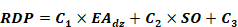
Where C1, C2 and C3
are selected from the following table.
|
|
Skylit Daylit
Zones |
Primary Sidelit
Daylit Zones |
Secondary Sidelit
Daylit Zones |
|
Illuminance
Setpoint |
C1 |
C2 |
C3 |
C1 |
C2 |
C3 |
C1 |
C2 |
C3 |
|
≤ 200 lux |
3927 |
0 |
3051 |
1805 |
-0.40 |
3506 |
7044 |
-3.32 |
1167 |
|
≤ 1000
lux |
12046 |
0 |
-421 |
6897 |
-7.22 |
475 |
1512 |
-2.88 |
-22 |
|
> 1000
lux |
5900 |
0 |
-516 |
884 |
-5.85 |
823 |
212 |
-0.93 |
57 |
Illuminance Setpoint: This is defined by the
user, and is entered by the user, subject to the limits specified in
Appendix 5.4A, determined from the space type.
Source Orientation (SO): The angle of the
outward facing normal of the daylight source’s parent surface projected
onto a horizontal plane, expressed as degrees from south. This is not a
user input but is calculated from the geometry of the parent surface. For
skylights, the source orientation is not applicable. For vertical fenestration, it is defined:

Where: Azimuth is defined as the azimuth of the parent
object containing the fenestration associated with the preliminary
reference point.
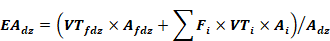
Effective Aperture (EA): For this calculation,
effective aperture represents the effectiveness of all sources which
illuminate a specific reference position in contributing to the daylight
available to the associated daylit zone. In cases where daylit zones from
multiple fenestration objects intersect, the effective aperture of an
individual daylit zone is adjusted to account for those intersections
according to the following rules:
•
For skylit and primary sidelit daylit zones, intersections with
other skylit or primary sidelit daylit zones are considered.
•
For secondary sidelit daylit zones, intersections with any toplit
or sidelit (primary or secondary) daylit zones are considered.
Effective aperture is defined as follows:
Where:
|
EAdz |
Is the combined effective aperture of all
daylight sources illuminating a specific daylit zone. |
|
VTfdz |
Is the user specified visible transmittance of
the fenestration object directly associated with the daylit
zone. |
|
Afdz |
Is the area of the fenestration object directly
associated with the daylit zone. |
|
VTi |
Is the user specified visible transmittance of
the fenestration object associated with each intersecting daylit
zone. |
|
Ai |
Is the area of the fenestration object directly
associated with each intersecting daylit zone. |
|
Fi |
Is the fraction of intersecting area between the
daylit zone in question and each intersecting daylit zone:

|
|
Adzi |
Is the area of each intersecting daylit zone
(including area that might fall outside a space or exterior
boundary). |
|
Adz |
Is the area of the daylit zone (including area
that might fall outside a space or exterior
boundary). |
First Reference Position: Select the preliminary
reference point with the highest relative daylight potential (RDP) from
among all preliminary reference points located within either top or
primary sidelit daylit zones. If multiple reference points have identical
RDPs, select the reference point geometrically closest to the centroid of
the space.
Second Reference Position: Select the
preliminary reference point with the highest RDP from amongst all
remaining preliminary reference points located within either top or
primary sidelit daylit zones. If multiple reference points have identical
RDPs, select the reference point geometrically closest to the centroid of
the space. |
|
Standard Design |
Reference positions for the standard design shall be
selected using the same procedure as those selected for the proposed
design. |
|
Standard Design:
Existing Buildings |
Additions or alternations of lighting in spaces trigger
the daylighting control requirements whenever the total installed lighting
in the daylit zone is 120 W or greater, and the reference positions shall
be determined in the same manner as with new construction. This only
applies when alterations or additions to the lighting in an existing
building trigger daylighting control requirements. |
|
Illumination Adjustment Factor |
|
Applicability |
All Daylighted Spaces |
|
Definition |
Recent studies have shown that the split flux
interreflection component model used in many simulation programs
overestimates the energy savings due to daylighting, particularly deep in
the space. A set of two adjustment factors is provided, one for the
primary daylit zone and one for the secondary daylit zone.
For simulation purposes, the input daylight illuminance
setpoint will be modified by the illuminance adjustment factor as
follows:

|
|
Units |
Unitless |
|
Input Restrictions |
Prescribed values for space type in Appendix
5.4A |
|
Standard Design |
The standard design illumination adjustment factors
shall match the proposed |
|
Standard Design:
Existing Buildings |
Same as new construction when skylights are
added/replaced and general light is altered. |
|
Fraction of Controlled Lighting |
|
Applicability |
Daylighted Spaces |
|
Definition |
The fraction of the general lighting power in the
primary and skylit daylit zone, or secondary sidelit daylit zone that is
controlled by daylighting controls. |
|
Units |
Numeric: fraction for primary and skylit daylit zone,
and fraction for secondary zone |
|
Input Restrictions |
As designed for secondary daylit areas. If the proposed
design has no daylight controls in the secondary daylit area the value is
set to 0 for the general lights in the secondary daylit area. Primary and
skylit daylit area fraction of controlled general lighting shall be as
designed when the daylight control requirements building descriptor
indicates that they are not required, and shall be 1 when controls are
required. |
|
Standard Design |
When daylight controls are required according to the
daylight control requirements building descriptor in either the primary
daylit and skylit zone, or the secondary daylit zone, or both, the
fraction of controlled lighting shall be 1. |
|
Standard Design:
Existing Buildings |
Same as for new construction when skylights are
added/replaced, and general light is altered. |
|
Daylighting Control Type |
|
Applicability |
Daylighted Spaces |
|
Definition |
The type of control that is used to control the
electric lighting in response to daylight available at the reference
point.
Options:
•
Stepped switching controls vary the electric input power and
lighting output power in discrete equally spaced steps. At each step, the
fraction of light output is equal to the fraction of rated power.
•
Continuous dimming controls have a fraction to rated power to
fraction of rated output that is a linear interpolation of the minimum
power fraction at the minimum diming light fraction to rated power (power
fraction = 1.0) at full light output. See Figure 8: Example Continuous Dimming
Control
Continuous dimming + off controls are the same as
continuous dimming controls except that these controls can turn all the
way off when none of the controlled light output is needed. See the
example control chart below.
Figure 8:
Example Continuous Dimming Control
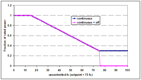
Source: NORESCO for
California Energy Commission |
|
Units |
List (see above) |
|
Input Restrictions |
As designed |
|
Standard Design |
Standard design uses continuous daylighting
control. |
|
Standard Design:
Existing Buildings |
Same as for new construction when skylights are
added/replaced, and general light is altered. |
|
Minimum Dimming Power Fraction |
|
Applicability |
Daylit spaces |
|
Definition |
The minimum power fraction when controlled lighting is
fully dimmed. Minimum power fraction = minimum power / full rated power.
|
|
Units |
Numeric: fraction |
|
Input Restrictions |
As designed, specified from luminaire type (not a user
input) |
|
Standard Design |
Standard design uses continuous dimming control with a
minimum dimming power fraction from Table
8: Standard Design Power/Light Output Fraction. Where the controlled
luminaire type, input by the user, determines the minimum dimming power
fraction. |
|
Standard Design: Existing Buildings |
Same as for new construction when skylights are
added/replaced, and general light is altered. |
|
Minimum Dimming Light Fraction |
|
Applicability |
Daylighting and dimming controls |
|
Definition |
The minimum light output when controlled lighting is
fully dimmed. Minimum light fraction = minimum light output / rated light
output. |
|
Units |
Numeric: fraction |
|
Input Restrictions |
As designed |
|
Standard Design |
Standard design uses continuous dimming control with a
minimum dimming light fraction from Table
8: Standard Design Power/Light Output Fraction. Where the controlled
luminaire type, input by the user, determines the minimum dimming power
fraction. |
|
Standard Design:
Existing Buildings |
Same as for new construction when skylights are
added/replaced, and general light is altered. |
|
Light
Source |
Power
Fraction |
Light Output
Fraction |
|
LED |
0.1 |
0.1 |
|
Linear Fluorescent |
0.2 |
0.2 |
|
Mercury Vapor |
0.3 |
0.2 |
|
Metal Halide |
0.45 |
0.2 |
|
High Pressure Sodium |
0.4 |
0.2 |
|
CFL |
0.4 |
0.2 |
|
Incandescent |
0.5 |
0.2 |
5.4.6
Receptacle Loads
Receptacle loads contribute to heat
gains in spaces and directly use energy.
|
Receptacle Power |
|
Applicability |
All building projects |
|
Definition |
Receptacle power is power for typical general service loads
in the building. Receptacle power includes equipment loads normally
served through electrical receptacles, such as office equipment and
printers, but does not include either task lighting or equipment
used for HVAC purposes. Receptacle power values are slightly higher than
the largest hourly receptacle load that is actually modeled because the
receptacle power values are modified by the receptacle schedule, which
approaches but does not exceed 1.0. |
|
Units |
Total power (W) or the space power density (W/ft²)
Compliance software shall also use the following
prescribed values to specify the latent heat gain fraction and the
radiative/convective heat gain split.
For software that specifies the fraction of the heat
gain that is lost from the space, this fraction shall be prescribed at
0.
Heat Gain Fractions:
|
|
Radiative |
Latent |
Convective |
|
Receptacle Power |
0.20 |
0.00 |
0.80 |
|
Gas Equipment Power |
0.15 |
0.00 |
0.00 |
|
|
Input Restrictions |
Prescribed to values from Appendix 5.4A |
|
Standard Design |
Same as proposed |
|
Standard Design:
Existing Buildings |
Same as for new construction |
|
Receptacle Schedule |
|
Applicability |
All projects |
|
Definition |
Schedule for receptacle power loads used to adjust the
intensity on an hourly basis to reflect time-dependent patterns of
usage. |
|
Units |
Data structure: schedule, fraction |
|
Input Restrictions |
Prescribed to schedule in Appendix 5.4A |
|
Standard Design |
Same as proposed |
|
Standard Design:
Existing Buildings |
Same as for new construction |
Commercial refrigeration equipment includes
the following:
•
Walk-in refrigerators
•
Walk-in freezers
•
Refrigerated casework
Refrigeration equipment is modeled
as neutral plug loads, with standard design power matching the proposed
design.
|
Refrigeration Modeling Method |
|
Applicability |
All buildings that have commercial refrigeration for
cold storage or display |
|
Definition |
The method used to estimate refrigeration energy and to
model the
thermal interaction with the space where casework is located. Two methods
are included in this manual:
•
Title
24 defaults. With this method, the power density values provided in
Appendix 5.4A are used; schedules are assumed to be continuous
operation.
|
|
Units |
List (see above) |
|
Input Restrictions |
The Title 24 defaults shall be used. |
|
Standard Design |
Title 24 defaults |
|
Standard Design:
Existing Buildings |
Same as for new construction |
|
Refrigeration Power |
|
Applicability |
All buildings that have commercial refrigeration for
cold storage or display |
|
Definition |
Commercial refrigeration power is the average power for
all commercial refrigeration equipment, assuming constant year-round
operation. Equipment includes walk-in refrigerators and freezers, open
refrigerated casework, and closed refrigerated casework. It does not
include residential type refrigerators used in kitchenettes or
refrigerated vending machines. These are covered under receptacle
power. |
|
Units |
W/ft2 |
|
Input Restrictions |
With the Title 24 defaults method, the values in
Appendix 5.4A are prescribed. These values are multiplied times the floor
area of the rated building to estimate the refrigeration power. |
|
Standard Design |
Refrigeration power is the same as the proposed design
when the Title 24 defaults are used. |
|
Standard Design:
Existing Buildings |
Same as for new construction |
5.4.8
Elevators, Escalators and Moving Walkways
Elevators, escalators and moving
walkways account for 3 percent to 5 percent of electric energy use in buildings.
Buildings up to about five to seven stories typically use hydraulic elevators
because of their lower initial cost. Mid-rise buildings commonly use traction
elevators with geared motors, while high-rise buildings typically use gearless
systems where the motor directly drives the sheave. The energy-using components
include the motors and controls as well as the lighting and ventilation systems for
the cabs.
Elevators, escalators, and moving
walkways are modeled as a plug loads, with the standard design power matching
the proposed design.
|
Elevator/Escalator Power |
|
Applicability |
All buildings that have commercial elevators,
escalators, or moving walkways |
|
Definition |
The power for elevators, escalators and moving walkways
are modeled as plug loads. |
|
Units |
W/unit |
|
Input Restrictions |
The power values are prescribed for the proposed
design. |
|
Standard Design |
Same as the proposed design |
|
Standard Design:
Existing Buildings |
Not applicable |
|
Elevator/Escalator Schedule |
|
Applicability |
All buildings that have commercial elevators,
escalators, or moving walkways |
|
Definition |
The schedule of operation for elevators, escalators,
and moving walkways. This is used to convert elevator/escalator power to
energy use. |
|
Units |
Data structure: schedule, state |
|
Input Restrictions |
The operating schedule is prescribed and indicated in
Appendix 5.4B. |
|
Standard Design |
Same as the proposed design |
|
Standard Design:
Existing Buildings |
Not applicable |
5.4.9
Process, Gas
Commercial gas equipment includes the
following:
•
Ovens
•
Fryers
•
Grills
•
Other equipment
The majority of gas equipment is
located in the space and may contribute both sensible and latent heat. Gas
equipment is modeled by specifying the rate of peak gas consumption and a
fractional schedule that is prescribed in Appendix 5.4B. The procedure consists
of prescribed power and energy values for use with both the proposed and
standard design buildings. No credit for commercial gas energy efficiency
features is offered.
The prescribed values are provided
in Appendix 5.4A. Schedules are defaulted to be continuous operation.
|
Gas Equipment Power |
|
Applicability |
All buildings that have commercial gas
equipment |
|
Definition |
Commercial gas power is the average power for all
commercial gas equipment, assuming constant year-round
operation. |
|
Units |
Btu/h-ft²
Compliance software shall also use the following
prescribed values to specify the latent heat gain fraction and the
radiative/convective heat gain split.
For software that specifies the fraction of the heat
gain that is lost from the space, this fraction shall be prescribed at
0.
Gas Equipment Power Heat Gain Fractions:
Radiative = 0.15, Latent = 0, Convective = 0 |
|
Input Restrictions |
The values in Appendix 5.4A are prescribed. However,
these values may be overridden with a “0” value for buildings that are
designed to use only electricity as the source. |
|
Standard Design |
Same as the proposed design |
|
Standard Design:
Existing Buildings |
Not applicable |
|
Gas Equipment Schedule |
|
Applicability |
All buildings that have commercial gas
equipment |
|
Definition |
The schedule of operation for commercial gas equipment.
This is used to convert gas power to energy use. |
|
Units |
Data structure: schedule, fractional |
|
Input Restrictions |
Continuous operation is prescribed. |
|
Standard Design |
Same as the proposed design |
|
Standard Design:
Existing Buildings |
Not applicable |
|
Gas Equipment Location |
|
Applicability |
All buildings that have commercial gas
equipment |
|
Definition |
The assumed location of the gas equipment for modeling
purposes. |
|
Units |
List (in the space or external) |
|
Input Restrictions |
As designed. |
|
Standard Design |
Same as the proposed design |
|
Standard Design:
Existing Buildings |
Not applicable |
|
Radiation Factor |
|
Applicability |
Gas appliances located in the space |
|
Definition |
The fraction of heat gain to appliance energy
use |
|
Units |
Fraction |
|
Input Restrictions |
Default value is 0.15. Other values can be used when a
detailed inventory of equipment is known. The override value shall be
based on data in Table 5C, Chapter 18, ASHRAE HOF, 2009, or similar
tested information from the manufacturer. |
|
Standard Design |
Same as the proposed design |
|
Standard Design:
Existing Buildings |
Not applicable |
|
Usage
Factor |
|
Applicability |
Gas
appliances located in the space |
|
Definition |
A duty cycle or usage factor to appliance energy
use.
The radiation factor and usage factor are used together
to determine the sensible heat gain to the space:
Qsens = Qinput x FU x
FR
Where Qinput is the heat input of the
equipment in Btu/h or Btu/h-ft2,
FU is the usage factor and
FR is the
radiation factor |
|
Units |
Fraction |
|
Input
Restrictions |
Default
value is 0.70. Other values can be used when a detailed inventory of
equipment is known. The override value shall be based on data in Table 5C,
Chapter 18, ASHRAE HOF, 2009, or similar tested information from the
manufacturer. |
|
Standard
Design |
Same as
the proposed design |
|
Standard Design:
Existing
Buildings |
Not
applicable |
|
Gas Process Loads |
|
Applicability |
Spaces with process loads |
|
Definition |
Process load is the gas energy consumption in the conditioned space of a building resulting from an
activity or treatment not related to the space conditioning, lighting, service
water heating, or ventilating of a building as it relates to human occupancy.
Process load may include sensible and/or latent components.
Compliance software shall model and simulate process loads
only if the amount of the process energy and the location and type of
process equipment are specified in the construction documents. This
information shall correspond to specific special equipment shown on the
building plans and detailed in the specifications. |
|
Units |
Data structure: sensible (Btu/h), latent
(Btu/h) |
|
Input Restrictions |
Compliance software shall receive input for sensible
and/or latent process load for each zone in the proposed design. The
process load input shall include the amount of the process load
(Btu/h-ft2) and the thermal zone where the process equipment is located.
The modeled information shall be consistent with the plans and
specifications of the building. |
|
Standard Design |
The standard design shall use the same gas process
loads and sensible and latent contribution and radiative/convective split
for each zone as the proposed design. |
|
Standard Design:
Existing Buildings |
Same as new construction |
|
Electric Process Loads |
|
Applicability |
Spaces with electric process loads |
|
Definition |
Process load is the electrical energy consumption in
the conditioned space of a building resulting from an activity or
treatment not related to the space conditioning, lighting, service water
heating, or ventilating of a building as it relates to human
occupancy.
Data center loads including transformers, uninterruptible
power supplies, power delivery units, server fans and power supplies are
considered receptacle loads, not process loads, and the equipment
schedules are given in Appendix 5.4B.
Compliance software shall model and simulate process
loads only if the amount of the process energy and the location and type
of process equipment are specified in the construction documents. This
information shall correspond to specific special equipment shown on the
building plans and detailed in the specifications. The compliance software
shall inform the user that the software will output process loads
including the types of process equipment and locations on the compliance
forms. |
|
Units |
Data structure: load
(kW)
For electric process loads,
the radiative fraction shall be defaulted to 0.2 and the convective
fraction shall be defaulted to 0.8 by the compliance software. The user
may enter other values for the radiative/convective split, but the
compliance software shall verify that the values add to 1. |
|
Input Restrictions |
Compliance software shall receive input for sensible
and/or latent process load for each zone in the proposed design. The
process load input shall include the amount of the process load
(Btu/h-ft2) and the thermal zone where the process equipment is
located. The modeled information shall be consistent with the plans and
specifications of the building. |
|
Standard Design |
The standard design shall use the same process loads
and radiative/convective split for each zone as the proposed
design. |
|
Standard Design:
Existing Buildings |
Same as new construction |
|
Gas Process Load Schedule |
|
Applicability |
All buildings that have commercial gas
equipment |
|
Definition |
The schedule of process load operation. Used to convert
gas power to energy use. |
|
Units |
Data structure: schedule,
fractional |
|
Input Restrictions |
As designed. |
|
Standard Design |
Same as the proposed design |
|
Standard Design:
Existing Buildings |
Not applicable |
|
Electric Process Load Schedule |
|
Applicability |
All buildings that have commercial gas
equipment |
|
Definition |
The schedule of electric process load
operation. |
|
Units |
Data structure: schedule,
fractional |
|
Input Restrictions |
As designed. |
|
Standard Design |
Same as the proposed design |
|
Standard Design:
Existing Buildings |
Not applicable |
5.4.10
Water Heating Use
This section defines the water
heating load (use rate) and system requirements on a space level.
|
Space Water Heating Use Rate |
|
Applicability |
All spaces |
|
Definition |
The water heating use rate for a space in a building |
|
Units |
Gal/h |
|
Input Restrictions |
The values in Appendix 5.4A are prescribed. |
|
Standard Design |
Same as the proposed design |
|
Standard Design:
Existing Buildings |
Not applicable |
|
Space Water Heating Fuel Type |
|
Applicability |
All spaces |
|
Definition |
A mapping that defines the standard design water
heating fuel type for a space |
|
Units |
List; gas or electric |
|
Input Restrictions |
As designed |
|
Standard Design |
Prescribed from the table in Appendix 5.4A |
|
Standard Design:
Existing Buildings |
Not applicable |