5.8 HVAC Primary Systems

5.8.1    Boilers

Boiler Name

Applicability

All boilers

Definition

A unique descriptor for each boiler, heat pump, central heating heat-exchanger, or heat recovery device

Units

None

Input Restrictions

User entry

Where applicable, this should match the tags that are used on the plans for the proposed design.

Standard Design

For healthcare facilities, same as the Proposed Design. For all others, Boilers are only designated in the standard design if the baseline system type uses hot water for space heating.

Standard Design:

Existing Buildings


Boiler Fuel Source

Applicability

All boilers

Definition

The fuel source for the central heating equipment

The choices are:

      Gas

      Oil

      Electricity

Units

List (see above)

Input Restrictions

As designed

This input is restricted, based on the choice of boiler type, according to the following rules:


Electricity

Gas

Steam

Steam Boiler

n/a

n/a

Allowed

Hot Water Boiler

n/a

Allowed

n/a

Standard Design

For healthcare facilities, same as the Proposed Design. For all others, Gas

Standard Design:

Existing Buildings

Same as proposed for existing, unaltered; same as new construction if altered


Boiler Type

Applicability

All boilers

Definition

The fuel source for the central heating equipment

The choices are:

      Gas

      Oil

      Electricity

Units

List (see above)

Input Restrictions

As designed

Standard Design

For healthcare facilities, same as the Proposed Design. For all others, Hot water boiler

Standard Design:

Existing Buildings

Same as proposed for existing, unaltered; same as new construction if altered


Boiler Draft Type

Applicability

All boilers

Definition

How combustion airflow is drawn through the boiler.

The choices are natural (sometimes called atmospheric) or mechanical.

Natural draft boilers use natural convection to draw air for combustion through the boiler. Natural draft boilers are subject to outside air conditions and the temperature of the flue gases.

Mechanical draft boilers enhance the air flow in one of three ways: 1) induced draft, which uses ambient air, a steam jet, or a fan to induce a negative pressure which pulls flow through the exhaust stack; 2) forced draft, which uses a fan and ductwork to create a positive pressure that forces air into the furnace, or 3) balanced draft, which uses both induced draft and forced draft methods to bring air through the furnace, usually keeping the pressure slightly below atmospheric.

Units

List (see above)

Input Restrictions

As designed

Standard Design

For healthcare facilities, same as the Proposed Design. For all others, Mechanical (forced)

Standard Design:

Existing Buildings


Number of Identical Boiler Units

Applicability

All boilers

Definition

The number of identical units for staging

Units

Numeric: integer

Input Restrictions

As designed; default is 1

Standard Design

The standard design shall have one boiler when the standard design plant serves a conditioned floor area of 15,000 ft2 or less and have two equally size boilers for plants serving more than 15,000 ft2.

Standard Design:

Existing Buildings


Boiler Design Capacity

Applicability

All boilers

Definition

The heating capacity at design conditions

Units

Btu/h


Input Restrictions

As designed

If unmet load hours exceed 150, the user may need to manually adjust boiler design capacity

Standard Design

The boiler is sized to be 25 percent larger than the peak loads of the standard design. Standard design boilers shall be sized using weather files containing 99.6 percent heating design temperatures and 0.5 percent dry-bulb and 1 percent wet-bulb cooling design temperatures.

Standard Design:

Existing Buildings


Boiler Efficiency Type

Applicability

All boilers

Definition

The full load efficiency of a boiler is expressed as one of the following:

      Annual fuel utilization efficiency (AFUE) is a measure of the boiler’s efficiency over a predefined heating season.

      Thermal efficiency (Et) is the ratio of the heat transferred to the water divided by the heat input of the fuel.

      Combustion efficiency (Ec) is the measure of how much energy is extracted from the fuel and is the ratio of heat transferred to the combustion air divided by the heat input of the fuel.

Units

List (see above)

Input Restrictions

None

Standard Design

AFUE for all gas and oil-fired boilers with less than 300,000 Btu/h capacity.

Thermal efficiency (Et) for all gas and oil-fired boilers with capacities between 225,000 and 2,500,000 Btu/h.

Combustion efficiency (Ec), for all gas and oil-fired boilers with capacities above 2,500,000 Btu/h.

Standard Design:

Existing Buildings


Boiler Efficiency

Applicability

All boilers

Definition

The full load efficiency of a boiler at rated conditions (see efficiency type above) expressed as a dimensionless ratio of output over input. The software must accommodate input in either thermal efficiency (Et), combustion efficiency (Ec), or AFUE. The software shall make appropriate conversions to thermal efficiency if either AFUE or combustion efficiency is entered as the rated efficiency.

Where AFUE is provided, Et shall be calculated as follows:

75% ≤ AFUE < 80%

Et=0.1(AFUE+72.5%)

80% ≤ AFUE ≤ 100%

Et=0.875(AFUE+10.5%)

If combustion efficiency is entered, the compliance software shall convert the efficiency to thermal efficiency by the relation:

Et=Ec-0.015

All electric boilers will have an efficiency of 98 percent.


Units

Ratio

Input Restrictions

As designed

Standard Design

Boilers for the standard design are assumed to have the minimum efficiency as listed in Table E-4 of the California Appliance Efficiency Regulations.

Standard Design:

Existing Buildings


Boiler Part-Load Performance Curve

Applicability

All boilers

Definition

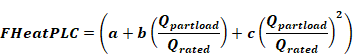
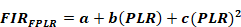
An adjustment factor that represents the percentage full load fuel consumption as a function of the percentage full load capacity. This curve shall take the form of a quadratic equation as follows:


Where:

FHeatPLC

The fuel heating part-load efficiency curve

Fuelpartload

The fuel consumption at part-load conditions (Btu/h)

Fueldesign

The fuel consumption at design conditions (Btu/h)

Qpartload

The boiler capacity at part-load conditions (Btu/h)

Qrated

The boiler capacity at design conditions (Btu/h)

a

Constant

b

Constant

c

Constant


Units

Ratio

Input Restrictions

Prescribed to the part-load performance curve in the ACM Appendix 5.7, based on the boiler draft type.

Standard Design

The standard design uses the mechanical draft fan curve in Appendix 5.7.

Standard Design:

Existing Buildings


Boiler Forced Draft Fan Power

Applicability

All mechanical draft boilers

Definition

The fan power of the mechanical draft fan at design conditions.

Units

Nameplate horsepower

Input Restrictions

As designed

The software shall convert the user entry of motor horsepower to fan power in watts by the following equation:

Fan Power=Motor HP(7.46)(0.5)

Standard Design

For healthcare facilities, same as the Proposed Design. For all others, Sized for an energy input ratio of 0.001018 (0.2984 W per kBtu/h heat input)

Standard Design:

Existing Buildings


Boiler Minimum Unloading Ratio

Applicability

All boilers

Definition

The minimum unloading capacity of a boiler expressed as a percentage of the rated capacity. Below this level, the boiler must cycle to meet the load.

Units

Percent (%)

Input Restrictions

As designed

If the user does not use the default value, the software must indicate that supporting documentation is required on the output forms. Fixed at 1 percent (this accounts for jacket losses and start/stop losses).

Standard Design

For healthcare facilities, same as the Proposed Design. For all others, 1 percent

Standard Design:

Existing Buildings


Boiler Minimum Flow Rate

Applicability

All boilers

Definition

The minimum flow rate recommended by the boiler manufacturer for stable and reliable operation of the boiler

Units

Gpm

Input Restrictions

As designed

If the boiler(s) is piped in a primary only configuration in a variable flow system then the software shall assume there is a minimum flow bypass valve that allows the hot water pump to bypass water from the boiler outlet back to the boiler inlet to maintain the minimum flow rate when boiler is enabled.

Note: The boiler entering water temperature must accurately reflect the mixed temperature (colder water returning from the coil(s) and hotter bypass water) to accurately model boiler efficiency as a function of boiler entering water temperature.

Standard Design

For healthcare facilities, same as the Proposed Design. For all others, 0 gpm

Standard Design:

Existing Buildings


Hot Water Supply Temperature

Applicability

All boilers

Definition

The temperature of the water produced by the boiler and supplied to the hot water loop

Units

Degrees Fahrenheit (°F)

Input Restrictions

As designed

Standard Design

For healthcare facilities, same as the Proposed Design. For all others, Use 180°F for standard design boiler

Standard Design:

Existing Buildings


Hot Water Return Temperature

Applicability

All boilers

Definition

The temperature of the water returning to the boiler from the hot water loop

Units

Degrees Fahrenheit (°F)

Input Restrictions

As designed.

Standard Design

For healthcare facilities, same as the Proposed Design. For all others, Use 140°F for standard design boiler

Standard Design:

Existing Buildings


Hot Water Supply Temperature Reset

Applicability

All boilers

Definition

Variation of the hot water supply temperature with outdoor air temperature

Units

Degrees Fahrenheit (°F)

Input Restrictions

As designed (not allowed for non-condensing boilers)

Standard Design

For healthcare facilities, same as the Proposed Design. For all others, The hot water supply temperature should vary according to the following:

      180°F when outside air is < 20°F

      Ramp linearly between 180°F and 150°F when outdoor air is between 20°F and 50°F

      150°F when outdoor air is > 50°F

Standard Design:

Existing Buildings


5.8.2    Chillers

Chiller Name

Applicability

All chillers

Definition

A unique descriptor for each chiller

Units

Text, unique

Input Restrictions

User entry; where applicable, this should match the tags that are used on the plans

Standard Design

For healthcare facilities, same as the Proposed Design. For all others, Chillers are only designated when the standard design system uses chilled water

Standard Design:

Existing Buildings


Chiller Type

Applicability

All chillers

Definition

The type of chiller, either a vapor-compression chiller or an absorption chiller.

Vapor compression chillers operate on the reverse Rankine cycle, using mechanical energy to compress the refrigerant, and include:

      Reciprocating*

      Scroll*

      Screw*

      Centrifugal – uses rotating impeller blades to compress the air and impart velocity

      Direct-Fired Single Effect Absorption – uses a single generator and condenser

      Direct-Fired Double Effect Absorption – uses two generators/ concentrators and condensers, one at a lower temperature and the other at a higher temperature. It is more efficient than the single effect but it must use a higher temperature heat source.

      Indirect-Fired Double Effect Absorption

      Gas Engine-Driven

*Positive displacement – includes reciprocating (piston-style), scroll and screw compressors

Units

List (see above). The software shall support all chiller types listed above.

Input Restrictions

As designed

Standard Design

For healthcare facilities, same as the Proposed Design. For all others, The standard design chiller is based on the design capacity of the standard design as follows:

Table 12: Type and Number of Chillers

Building Peak Cooling Load

Number and type of chiller(s)

≤ 300 tons

One water-cooled screw chiller

300 < Load < 600

Two water-cooled screw chillers, sized equally

≥ 600 tons

A minimum of two water-cooled centrifugal chillers, sized to keep the unit size below 800 tons


Standard Design:

Existing Buildings


Number of Identical Chiller Units

Applicability

All chillers

Definition

The number of identical units for staging

Units

None

Input Restrictions

As designed; default is 1

Standard Design

For healthcare facilities, same as the Proposed Design. For all others, From the number indicated in Chiller Type

Standard Design:

Existing Buildings


Number of Identical Chiller Units

Applicability

All chillers

Definition

The fuel source for the chiller

The choices are:

      Electricity (for all vapor-compression chillers)

      Gas (absorption units only, designated as direct-fired units)

      Hot water (absorption units only, designated as indirect-fired units)

      Steam (absorption units only, designated as indirect-fired units)

Units

List (see above)

Input Restrictions

As designed

This input is restricted, based on the choice of chiller type, according to the following rules:


Electricity

Gas

Hot Water

Steam

Reciprocating

Allowed

n/a

n/a

n/a

Scroll

Allowed

n/a

n/a

n/a

Screw

Allowed

n/a

n/a

n/a

Centrifugal

Allowed

n/a

n/a

n/a

Single Effect Absorption

n/a

Allowed

Allowed

Allowed

Direct-Fired Double Effect Absorption

n/a

Allowed

Allowed

Allowed

Indirect-Fired Absorption

n/a

Allowed

Allowed

Allowed


Standard Design

For healthcare facilities, same as the Proposed Design. For all others, Electricity

Standard Design:

Existing Buildings


Chiller Rated Capacity

Applicability

All chillers

Definition

The cooling capacity of a piece of heating equipment at rated conditions

Units

Btu/h or tons

Input Restrictions

As designed

The user may need to manually adjust the capacity if the number of unmet load hours exceeds 150.

Standard Design

Determine loads for standard design and oversize by 15 percent

Standard Design:

Existing Buildings


Chiller Rated Efficiency

Applicability

All chillers

Definition

The efficiency of the chiller (EER for air-cooled chillers, kW/ton for water-cooled electric chillers, and COP for fuel-fired and heat-driven chillers) at AHRI 550/590 rated full-load conditions

Units

Ratio (kW/ton, COP, EER, depending on chiller type and condenser type)

Water-cooled electric chiller - kW/ton

Air-cooled or evaporatively-cooled electric chiller - EER

All non-electric chillers – COP

Input Restrictions

As designed

Must meet the minimum requirements of Table 110.2-D.

Standard Design

Use the minimum efficiency requirements from Table 110.2-D Path B.

If chiller type is reciprocating, scroll, or screw, use the efficiency for positive displacement chillers from Table 110.2-D.

Standard Design:

Existing Buildings

Same as proposed if unaltered; same as new construction rules if altered or replacement


Integrated Part-Load Value

Applicability

All chillers

Definition

The part-load efficiency of a chiller developed from a weighted average of four rating conditions, according to AHRI Standard 550

Units

Ratio (kW/ton, COP, EER, depending on chiller type and condenser type)

Water-cooled electric chiller - kW/ton

Air-cooled or evaporatively-cooled electric chiller - EER

All non-electric chillers – COP

Input Restrictions

As designed; must meet the minimum requirements of Table 110.2-D

Standard Design

Not used

When the standard design system has a chiller, the standard design will always use Path B performance curves.

Standard Design:

Existing Buildings


Chiller Minimum Unloading Ratio

Applicability

All chillers

Definition

The minimum unloading capacity of a chiller expressed as a fraction of the rated capacity

Below this level the chiller must either cycle to meet the load or false-load the compressor (such as with hot gas bypass).

Table 13: Default Minimum Unloading Ratios

Chiller Type

Default Unloading Ratio

Reciprocating

25%

Screw

15%

Centrifugal

10%

Scroll

25%

Single Effect Absorption

10%

Double Effect Absorption

10%


Units

Percent (%)

Input Restrictions

As designed but constrained to a minimum value of 10 percent. If the user does not employ the default values, supporting documentation is required.

Standard Design

For healthcare facilities, same as the Proposed Design. For all others, Use defaults listed above

Standard Design:

Existing Buildings


Chiller Minimum Part Load Ratio

Applicability

All chillers

Definition

The minimum unloading capacity of a chiller expressed as a fraction of the rated capacity

Below this level the chiller must cycle to meet the load. If the chiller minimum part-load ratio (PLR) is less than the chiller minimum unloading ratio, then the compliance software shall assume hot gas bypass operation between the minimum PLR and the minimum unloading ratio.

Units

Percent (%)

Input Restrictions

As designed, but constrained to a minimum value of 10 percent. If the user does not employ the default values, supporting documentation is required.

Standard Design

For healthcare facilities, same as the Proposed Design. For all others, When the standard design has a screw chiller, the minimum PLR is 15 percent. When the standard design has a centrifugal chiller, the minimum PLR is 10 percent.

Standard Design:

Existing Buildings


Chiller Cooling Capacity Adjustment Curve

Applicability

All chillers

Definition

A curve or group of curves or other functions that represent the available total cooling capacity as a function of evaporator and condenser conditions and perhaps other operating conditions. The default curves are given as:

For air-cooled chillers:


For air-cooled chillers:


For water-cooled chillers:


Where:

Qavailable

Available cooling capacity at present evaporator and condenser conditions (MBH)

tchws

The chilled water supply temperature (°F)

tcws

The condenser water supply temperature (°F)

todb

The outside air dry-bulb temperature (°F)

Qrated

Rated capacity at AHRI conditions (MBH)

Note: If an air-cooled unit employs an evaporative condenser, todb is the effective dry-bulb temperature of the air leaving the evaporative cooling unit.

Separate curves are provided for Path A and Path B chillers in Appendix 5.7.

Units

Data structure

Input Restrictions

Prescribed curves are provided in Appendix 5.7 for the proposed design chiller type and the compliance path (A or B). If the default curves are overridden, supporting documentation is required.

Standard Design

For healthcare facilities, same as the Proposed Design (choose from available performance curves, no custom curves). For all others, Use prescribed curve for Path B chiller as applicable to the standard design chiller type.

Standard Design:

Existing Buildings


Electric Chiller Cooling Efficiency Adjustment Curves

Applicability

All chillers

Definition

A curve or group of curves that varies the cooling efficiency of an electric chiller as a function of evaporator conditions, condenser conditions and part-load ratio.

Note: For variable-speed chillers, the part-load cooling efficiency curve is a function of both part-load ratio and leaving condenser water temperature. The default curves are given as:


Variable Speed:

Air-Cooled:

Water-Cooled:


Where:

PLR

Part-load ratio based on available capacity (not rated capacity)

Qoperating

Present load on chiller (Btu/h)

Qavailable

Chiller available capacity at present evaporator and condenser conditions (Btu/h)

tchws

The chilled water supply temperature (°F)

t_cws

The condenser water supply temperature (°F)

todb

The outside air dry-bulb temperature (°F)

Prated

Rated power draw at AHRI conditions (kW)

Poperating

Power draw at specified operating conditions (kW)

Note: If an air-cooled chiller employs an evaporative condenser, todb is the effective dry-bulb temperature of the air leaving the evaporative cooling unit.

Units

Data structure

Input Restrictions

Curves are prescribed in Appendix 5.7 given the chiller capacity and type. A separate set of curves are provided for Path A chillers and Path B chillers. The path is determined by comparing software inputs of full-load efficiency and integrated part-load value with the requirements of standards Table 110.2-D.

Standard Design

For healthcare facilities, same as the Proposed Design. For all others, Use Path B curves specified in Appendix 5.7

Standard Design:

Existing Buildings


Fuel and Steam Chiller Cooling Efficiency Adjustment Curves

Applicability

All chillers

Definition

A curve or group of curves that varies the cooling efficiency of a fuel-fired or steam chiller as a function of evaporator conditions, condenser conditions, and part-load ratio. The default curves are given as follows:

Default curves for steam-driven single and double effect absorption chillers:


Default curves for direct-fired double effect absorption chillers:


The default curves for engine driven chillers are the same format as those for the steam-driven single and double effect absorption chillers but there are three sets of curves for different ranges of operation based on the engine speed.

Where:

PLR

Part-load ratio based on available capacity (not rated capacity)

FIR_FPLR

A multiplier on the fuel input ratio (FIR) to account for part-load conditions

FIRFT

A multiplier on the fuel input ratio (FIR) to account for the chiller water supply temperature and the condenser water temperature

FIRFT1

A multiplier on the fuel input ratio (FIR) to account for chilled water supply temperature

FIRFT2

A multiplier on the fuel input ratio (FIR) to account for condenser water supply temperature

CAPFT

A multiplier on the capacity of the chiller (Equation 45)

Qoperating

Present load on chiller (in Btu/h)

Q_available

Chiller available capacity at present evaporator and condenser conditions (in Btu/h)

chws

The chilled water supply temperature (in °F)

tcws

The condenser water supply temperature (in °F)

todb

The outside air dry-bulb temperature (°F)

Fuelrated

Rated fuel consumption at AHRI conditions (in Btu/h)

Fuelpartload

Fuel consumption at specified operating conditions (in Btu/h)


Units

Data structure

Input Restrictions

Restricted to curves specified in Appendix 5.7

Standard Design

Use prescribed curves specified in Appendix 5.7

Standard Design:

Existing Buildings


Chilled Water Supply Temperature

Applicability

All chillers

Definition

The chilled water supply temperature of the chiller at design conditions

Units

Degrees Fahrenheit (°F)

Input Restrictions

As designed

Standard Design

For healthcare facilities, same as the Proposed Design. For all others, The standard design chilled water supply temperature is set to 44°F.

Standard Design:

Existing Buildings


Chilled Water Return Temperature

Applicability

All chillers

Definition

The chilled water return temperature setpoint at design conditions

Units

Degrees Fahrenheit (°F)

Input Restrictions

As designed

Standard Design

For healthcare facilities, same as the Proposed Design. For all others, The standard design chilled water return temperature is set to 64°F.

Standard Design:

Existing Buildings


Chilled Water Supply Temperature Control Type

Applicability

All chillers

Definition

The method by which the chilled water setpoint temperature is reset

The chilled water setpoint may be reset based on demand or outdoor air temperature.

Units

List none, outside air-based reset, or demand-based reset

Input Restrictions

As designed

Standard Design

For healthcare facilities, same as the Proposed Design. For all others, Outside air-based reset

Standard Design:

Existing Buildings


Chilled Water Supply Temperature Reset

Applicability

All chillers

Definition

The reset schedule for the chilled water supply temperature. The chilled water setpoint may be reset based on demand or outdoor air temperature.

Units

Degrees Fahrenheit (°F)

Input Restrictions

As designed

Standard Design

For healthcare facilities, same as the Proposed Design. For all others, 10°F from design chilled water supply temperature

The chilled water supply temperature reset follows an outside air reset scheme, where the setpoint is 44°F at outside air conditions of 80°F dry-bulb and above; the setpoint is 54°F at outside air conditions of 60°F dry-bulb and below; and ramps linearly from 44°F to 54°F as the outside air dry-bulb temperature varies between 80°F and 60°F.

Standard Design:

Existing Buildings


Condenser Type

Applicability

All chillers

Definition

The type of condenser for a chiller

The choices are:

      Air-cooled

      Water-cooled

Air-cooled chillers use air to cool the condenser coils. Water-cooled chillers use cold water to cool the condenser and additionally need either a cooling tower or a local source of cold water. Evaporatively-cooled chillers are similar to air-cooled chillers, except a water mist is used to cool the condenser coil, making them more efficient.

Units

List (see above)

Input Restrictions

As designed

Standard Design

For healthcare facilities, same as the Proposed Design. For all others, the standard design chiller is always assumed to have a water-cooled condenser, although the chiller type will change depending on the design capacity.

Standard Design:

Existing Buildings


5.8.3    Cooling Towers

Standard Design Summary. Standard design system 6 has one or more cooling towers. One tower is assumed to be matched to each standard design chiller. Each standard design chiller has its own condenser water pump that operates when the chiller is brought into service.


Cooling Tower Name

Applicability

All cooling towers

Definition

A unique descriptor for each cooling tower

Units

Text, unique

Input Restrictions

User entry; where applicable, this should match the tags that are used on the plans

Standard Design

Descriptive name that keys the standard design building plant

Standard Design:

Existing Buildings


Cooling Tower Type

Applicability

All cooling towers

Definition

Type of cooling tower employed.

The choices are:

      Open tower, centrifugal fan

      Open tower, axial fan

Open cooling towers collect the cooled water from the tower and pump it directly back to the cooling system. Closed towers circulate the evaporated water over a heat exchanger to indirectly cool the system fluid.

Units

List (see above)

Input Restrictions

As designed

Standard Design

For healthcare facilities, same as the Proposed Design. For all others, The standard design cooling tower is an open tower axial fan device

Standard Design:

Existing Buildings


Cooling Tower Capacity

Applicability

All cooling towers

Definition

The tower thermal capacity per cell adjusted to Cooling Technology Institute (CTI) rated conditions of 95°F condenser water return, 85°F condenser water supply, and 78°F wet-bulb with a 3 gpm/nominal ton water flow. The default cooling tower curves below are at unity at these conditions.

Units

Btu/h


Input Restrictions

As designed

Standard Design

The standard design building chiller is autosized and increased by 15 percent. The tower is sized to supply 85°F condenser water at design conditions for the oversized chiller.

Standard Design:

Existing Buildings


Cooling Tower Number of Cells

Applicability

All cooling towers

Definition

The number of cells in the cooling tower

Each cell will be modeled as equal size. Cells are subdivisions in cooling towers into individual cells, each with their own fan and water flow, that allow the cooling system to respond more efficiently to lower load conditions.

Units

Numeric: integer

Input Restrictions

As designed

Standard Design

One cell per tower and one tower per chiller

Standard Design:

Existing Buildings


Cooling Tower Total Fan Horsepower

Applicability

All cooling towers

Definition

The sum of the nameplate rated horsepower (hp) of all fan motors on the cooling tower. Pony motors should not be included.

.Units

Gpm/hp or unitless if energy input ratio (EIR) is specified (if the nominal tons but not the condenser water flow is specified, the condenser design water flow shall be 3.0 gpm per nominal cooling ton).

Input Restrictions

As designed, but the cooling towers shall meet minimum performance requirements in Standards Table 110.2-G

Standard Design

For healthcare facilities, same as the Proposed Design. For all others, The cooling tower fan horsepower is 60 gpm/hp, with the following exceptions:

1)   Cooling towers in climate zones 1 or 16 shall set the standard design to the mandatory minimum, 42.1 gpm/hp

2)   Cooling towers with a design condenser water flow of 900 gpm or less shall set the standard design to the mandatory minimum, 42.1 gpm/hp

Standard Design:

Existing Buildings

42.1 gpm/hp


Cooling Tower Design Wet-Bulb

Applicability

All cooling towers

Definition

The design wet-bulb temperature that was used for selection and sizing of the cooling tower

Units

Degrees Fahrenheit (°F)

Input Restrictions

Specified from design wet-bulb conditions from Reference Appendix JA2 for the city where the building is located, or the city closest to where the building is located

Standard Design

Specified from design wet-bulb conditions from Reference Appendix JA2 for the city where the building is located, or from the city closest to where the building is located

Standard Design:

Existing Buildings


Cooling Tower Design Entering Water Temperature

Applicability

All cooling towers

Definition

The design condenser water supply temperature (leaving tower) that was used for selection and sizing of the cooling tower

Units

Degrees Fahrenheit (°F)

Input Restrictions

As designed; default to 85°F

Standard Design

85°F or 10°F above the design wet-bulb temperature, whichever is lower

Standard Design:

Existing Buildings


Cooling Tower Design Return Water Temperature

Applicability

All cooling towers

Definition

The design condenser water return temperature (entering tower) that was used for selection and sizing of the cooling tower

Units

Degrees Fahrenheit (°F)

Input Restrictions

As designed; default to 95°F

Standard Design

Set to a range of 10°F (10°F above the cooling tower design entering water temperature)

Standard Design:

Existing Buildings


Cooling Tower Capacity Adjustment Curve

Applicability

All cooling towers

Definition

A curve or group of curves that represent the available total cooling capacity as a function of outdoor air wet-bulb, condenser water supply, and condenser water return temperatures.

The default curves are given as follows:

Approach = Coeff(1) + Coeff(2)•FRair + Coeff(3)•(FRair)2 +Coeff(4)•(FRair)3 + Coeff(5)•FRwater + Coeff(6)•FRair•FRwater + Coeff(7)•(FRair)2•FRwater + Coeff(8)•(FRwater)2 + Coeff(9)•FRair•(FRwater)2 +

Coeff(10)•(FRwater)3 + Coeff(11)•Twb + Coeff(12)•FRair•Twb + Coeff(13)•(FRair)2•Twb + Coeff(14)•FRwater•Twb + Coeff(15)•FRair•FRwater•Twb + Coeff(16)•(FRwater)2•Twb +

Coeff(17)•(Twb)2 + Coeff(18)•FRair•(Twb)2 + Coeff(19)•FRwater•(Twb)2 + Coeff(20)•(Twb)3 + Coeff(21)•Tr + Coeff(22)•FRair•Tr + Coeff(23)•FRair•FRair•Tr + Coeff(24)•FRwater•Tr + Coeff(25)•FRair•FRwater•Tr +

Coeff(26)•(FRwater)2•Tr + Coeff(27)•Twb•Tr + Coeff(28)•FRair•Twb•Tr + Coeff(29)•FRwater•Twb•Tr +

Coeff(30)•(Twb)2•Tr + Coeff(31)•(Tr)2 + Coeff(32)•FRair•(Tr)2 + Coeff(33)•FRwater•(Tr)2 + Coeff(34)•Twb•(Tr)2 + Coeff(35)•(Tr)3


Where:

FRair – ratio of airflow to airflow at design conditions

FRwater – ratio of water flow to water flow at design conditions

Tr – tower range (°F)

Twb – wet-bulb temperature

Coefficients for this performance curve are provided in Appendix 5.7.


Units

Data structure

Input Restrictions

User must use one of the prescribed curves defined in Appendix 5.7

Standard Design

Use one of the prescribed curves defined in Appendix 5.7

Standard Design:

Existing Buildings


Cooling Tower Set Point Control

Applicability

All cooling towers

Definition

The type of control for the condenser water supply.

The choices are fixed or wet-bulb reset.

A fixed control will modulate the tower fans to provide the design condenser water supply temperature at all times when possible. A wet-bulb reset control will reset the condenser water setpoint to a fixed approach to outside air wet-bulb temperature. The approach defaults to 10°F. A lower approach may be used with appropriate documentation.

Units

List (see above)

Input Restrictions

As designed; default to 95°F

Standard Design

For healthcare facilities, same as the Proposed Design. For all others, Fixed at the 0.4 percent design wet-bulb temperature, which is prescribed and specified for each of the 86 weather data files

Standard Design:

Existing Buildings


Cooling Tower Capacity Control

Applicability

All cooling towers

Definition

Describes the modulation control employed in the cooling tower.

Choices include:

      Fluid Bypass provides a parallel path to divert some of the condenser water around the cooling tower at part-load conditions.

      Fan Cycling is a simple method of capacity control where the tower fan is cycled on and off. This is often used on multiple-cell installations.

      Two-Speed Fan/Pony Motor are the same from an energy perspective. A lower horsepower pony motor is an alternative to a two-speed motor. The pony motor runs at part-load conditions (instead of the full-sized motor) and saves fan energy when the tower load is reduced. Additional building descriptors are triggered when this method of capacity control is selected.

      Variable-Speed Fan is a variable frequency drive is installed for the tower fan so that the speed can be modulated.


Units

List (see above)

Input Restrictions

As designed

Standard Design

For healthcare facilities, same as the Proposed Design. For all others, Variable-speed fan

Standard Design:

Existing Buildings


Cooling Tower Low-Speed Airflow Ratio

Applicability

All cooling towers with two-speed or pony motors

Definition

The percentage full-load airflow that the tower has at low speed or with the pony motor operating; equivalent to the percentage full-load capacity when operating at low speed

Units

Ratio

Input Restrictions

As designed

Standard Design

For healthcare facilities, same as the Proposed Design. For all others, Not applicable

Standard Design:

Existing Buildings


Cooling Tower Low-Speed kW Ratio

Applicability

All cooling towers with two-speed or pony motors

Definition

The percentage full-load power that the tower fans draw at low speed or with the pony motor operating

Units

Ratio

Input Restrictions

Calculated, using the as-designed flow ratio and the cooling tower power adjustment curve below

Standard Design

For healthcare facilities, same as the Proposed Design. For all others, Not applicable

Standard Design:

Existing Buildings


Cooling Tower Power Adjustment Curve

Applicability

All cooling towers with VSD control

Definition

A curve that varies the cooling tower fan energy usage as a function of part-load ratio for cooling towers with variable speed fan control. The default curve is given as:


Where:

PLR

Part-load ratio based on available capacity (not rated capacity)

Qoperating

Present load on tower (in Btu/h)

Qavailable

Tower available capacity at present range, approach, and outside wet-bulb conditions (in Btu/h)

tOWB

The outside air wet-bulb temperature (°F)

tR

The tower range (°F)

tA

The tower approach (°F)

Prated

Rated power draw at CTI conditions (kW)

Poperating

Power draw at specified operating conditions (kW)


Refer to Appendix 5.7 for the fixed cooling tower curve coefficients.


Units

Data structure

Input Restrictions

User shall use only default curves

Standard Design

Use default curves given above

Standard Design:

Existing Buildings


Cooling Tower Minimum Speed

Applicability

All cooling towers with a VSD control

Definition

The minimum fan speed setting of a VSD controlling a cooling tower fan expressed as a ratio of full load speed

Units

Ratio

Input Restrictions

As designed; default is 0.50

Standard Design

For healthcare facilities, same as the Proposed Design. For all others, 0.5

Standard Design:

Existing Buildings


5.8.4    Water-side Economizers

None of the standard design building systems use a water-side economizer.


Water-Side Economizer Name

Applicability

All water-side economizers

Definition

The name of a water-side economizer for a cooling system

Units

Text, unique

Input Restrictions

Descriptive reference to the construction documents;  default is no water-side economizer

Standard Design

For healthcare facilities, same as the Proposed Design. For all others,  No water economizer

Standard Design:

Existing Buildings


Water Economizer Type

Applicability

All water-side economizers

Definition

The type of water-side economizer. Choices include:

      None

      Heat exchanger in parallel with chillers. This would be used with an open cooling tower and is often referred to as a non-integrated economizer because the chillers are locked out when the plant is in economizer mode.

      Heat exchanger in series with chillers. This would be used with an open cooling tower and is often referred to as integrated because the chillers can operate simultaneously with water economizer operation.

      Direct water economizer. This would be used with a closed cooling tower. In this case, a heat exchanger is not needed. This type works only as a non-integrated economizer (also known as strainer-cycle).

Units

List (see above)

Input Restrictions

As designed

Standard Design

For healthcare facilities, same as the Proposed Design. For all others,  No water economizer

Standard Design:

Existing Buildings


Water-Side Economizer HX Effectiveness

Applicability

Water-side economizers with an open cooling tower

Definition

The effectiveness of a water-side heat exchanger at design conditions

This is defined as:

Qecon=(mCHW)(CpCHW)(ε)(T(CHW,R)-T(CW,S))

Where:

Qecon

The maximum load that the economizer can handle

mCHW

The chilled water flow rate

CpCHW

The chilled water specific heat

TCHW,R

The chilled water return temperature

TCW,S

The condenser water supply temperature

WSEeff

The effectiveness of the water-side economizer coil

tea

The entering coil air dry-bulb temperature (°F)

tla

The leaving coil air dry-bulb temperature (°F)

tea

The entering coil water temperature (°F)


Units

Ratio

Input Restrictions

As designed; default is 60 percent

Standard Design

For healthcare facilities, same as the Proposed Design. For all others,  No water economizer

Standard Design:

Existing Buildings


Water-Side Economizer Heat Exchanger Heat Transfer Coefficient

Applicability

Water-side economizers with an open cooling tower

Definition

The heat transfer coefficient of the plate-and-frame heat exchanger with the waterside economizer

Units

Btu/h-°F

Input Restrictions

As designed

Standard Design

For healthcare facilities, same as the Proposed Design. For all others,  Not applicable

Standard Design:

Existing Buildings


Water-Side Economizer Approach

Applicability

All water-side economizers

Definition

The design temperature difference between the chilled water temperature leaving the heat exchanger and the condenser water inlet to the heat exchanger

Units

Degrees Fahrenheit (°F)

Input Restrictions

As designed; default is 4°F

Standard Design

For healthcare facilities, same as the Proposed Design. For all others,  No water economizer

Standard Design:

Existing Buildings


Water-Side Economizer Maximum CWS

Applicability

All water-side economizers

Definition

The control temperature (condenser water supply temperature) above which the water-side economizer is disabled

Units

Degrees Fahrenheit (°F)

Input Restrictions

As designed; default is 50°F

Standard Design

For healthcare facilities, same as the Proposed Design. For all others,  No water economizer

Standard Design:

Existing Buildings


Water-Side Economizer Availability Schedule

Applicability

All water-side economizers

Definition

A schedule which represents the availability of the water-side economizer

Units

Data structure: schedule, on/off

Input Restrictions

As designed

Standard Design

For healthcare facilities, same as the Proposed Design. For all others,  No water economizer

Standard Design:

Existing Buildings


Water-Side Economizer Auxiliary kW

Applicability

Water-side economizers with an open tower

Definition

The electrical input (pumps and auxiliaries) for a dedicated pump for the chilled water side of the heat exchanger

This power is in excess of the condenser water pumps and cooling tower fans for the system during water-side economizer operation.

Units

KW or kW/ton

Input Restrictions

As designed

Standard Design

For healthcare facilities, same as the Proposed Design. For all others,  No water economizer

Standard Design:

Existing Buildings


5.8.5    Pumps

Standard Design Summary - Hot water pumping in the standard design shall be modeled as a variable flow, primary only system. Two-way valves are assumed at the heating coils.

Chilled water pumping in the standard design (system 6) is a primary system. Each chiller has its own primary and condenser water pumps that operate when the chiller is activated.

General Notes - The building descriptors in this section are repeated for each pumping system. See the pump service building descriptor for a list of common pump services.


Pump Name

Applicability

All pumps

Definition

A unique descriptor for each pump

Units

Text, unique

Input Restrictions

User entry; were applicable, should match the tags that are used on the plans

Standard Design

Same as proposed design

If there is no equivalent in the proposed design, assign a sequential tag to each piece of equipment. The sequential tags should indicate the pump service as part of the descriptor (e.g., CW for condenser water, CHW for chilled water, or HHW for heating hot water).

Standard Design:

Existing Buildings


Pump Service

Applicability

All pumps

Definition

The service for each pump.

Choices include:

      Chilled water

      Chilled water (primary)

      Chilled water (secondary)

      Heating water

      Heating water (primary)

      Heating water (secondary)

      Service hot water

      Condenser water

      Loop water (for hydronic heat pumps)

Units

List (see above)

Input Restrictions

As designed

Standard Design

As needed by the standard design system

Standard Design:

Existing Buildings


Number of Pumps

Applicability

All pumps

Definition

The number of identical pumps in service in a particular loop, e.g., the heating hot water loop, chilled water loop, or condenser water loop

Units

Numeric: integer

Input Restrictions

As designed

Standard Design

There will be one heating hot water pump for each boiler, one chilled water pump, and one condenser water pump for each chiller.

Standard Design:

Existing Buildings


Water Loop Design

Applicability

All pumps

Definition

The heating and cooling delivery systems can consist of a simple primary loop system, or more complicated primary/secondary loops or primary/secondary/tertiary loops

Units

List (see above)

Input Restrictions

As designed

Standard Design

For healthcare facilities, same as the Proposed Design. For all others, Assume primary loops only for heating hot water; for chilled water loops, a primary loop design is assumed.

Standard Design:

Existing Buildings


Pump Motor Modeling Method

Applicability

All pumps

Definition

Software commonly models pumps in one of two ways. The simple method is for the user to enter the electric power per unit of flow (W/gpm). This method is commonly used for smaller systems. A more detailed method requires a specification of the pump head, design flow, impeller, and motor efficiency.

Units

List power-per-unit-flow or detailed

Input Restrictions

Detailed

Standard Design

Detailed for chilled water and condenser water pumps; power-per-unit-flow for heating hot water and service hot water pumps

Standard Design:

Existing Buildings


Pump Motor Power-Per-Unit-Flow

Applicability

All proposed design pumps that use the power-per-unit-flow method

Definition

The electric power of the pump divided by the flow at design conditions

Units

W/gpm

Input Restrictions

As designed

Standard Design

For healthcare facilities, same as the Proposed Design. For all others,  Not applicable for chilled water and condenser water pumps; 19 W/gpm for heating hot water and service hot water pumps

Standard Design:

Existing Buildings


Pump Motor Horsepower

Applicability

All pumps

Definition

The nameplate motor horsepower

Units

Horsepower (hp)

Input Restrictions

Constrained to be a value from the following standard motor sizes:

1/12, 1/8, ¼, ½, ¾, 1, 1.5, 2, 3, 5, 7.5, 10, 15, 20, 25, 30, 40, 50, 60, 75, 100, 125, 150, 200

Standard Design

Not applicable

Standard Design:

Existing Buildings


Pump Design Head

Applicability

All standard and proposed design pumps that use the detailed method

Definition

The head of the pump at design flow conditions

Units

ft of water

Input Restrictions

As designed but subject to an input restriction. The user inputs of pump design head, impeller efficiency, cooling tower design entering water temperature, and cooling tower design return water temperature shall be used to calculate the proposed brake horsepower. This shall be compared to the pump motor horsepower for the next smaller motor size (MHPi-1) than the one specified by the user (MHPi).

The proposed design for the pump design head shall be constrained so that the resulting brake horsepower is no smaller than 95 percent of the next smaller motor size:

Where:

design bhpprop

The brake horsepower used in the simulation

design bhpprop-user-head

The brake horsepower resulting from the user input of design head

MHPi

The pump motor horsepower specified by the user

i

The index into the standard motor size table for the user motor horsepower

MHPi-1

The motor horsepower for the next smaller motor size. For example, if the user-specified pump motor horsepower is 25, the next smaller motor size in the table above is 20

Since all other user inputs that affect the proposed design brake horsepower are not modified, the proposed design pump design head is adjusted in the same proportion as the pump brake horsepower in the equation above. If the user-entered pump design head results in a brake horsepower that is at least 95 percent of the horsepower of the next smaller motor size, no modification of the user input is required.

Standard Design

For healthcare facilities, same as the Proposed Design. For all others,  For chilled water pumps:

(40 ft) + (0.03 ft/ton) x [chiller plant nominal capacity (tons)]

(not to exceed 100 ft)

For condenser water pumps:

45 ft

Impeller Efficiency

Applicability

All pumps in proposed design that use the detailed modeling method

Definition

The full load efficiency of the impeller

Units

Ratio

Input Restrictions

As designed

Standard Design

For healthcare facilities, same as the Proposed Design. For all others,  Not applicable

Standard Design:

Existing Buildings


70%

Motor Efficiency

Applicability

All pumps in proposed design that use the detailed modeling method

Definition

The full load efficiency of the pump motor

Units

Ratio

Input Restrictions

For healthcare facilities, same as the Proposed Design. For all others,  As designed

Standard Design

The motor efficiency is taken from Table 11, using the next larger motor size than the calculated standard design brake horsepower

Standard Design:

Existing Buildings


Pump Minimum Speed

Applicability

All two-speed or variable-speed pumps

Definition

The minimum pump speed for a two-speed for variable-speed pump.

For two-speed pumps this is typically 0.67 or 0.5.

Note: The pump minimum speed is not necessarily the same as the minimum flow ratio, since the system head may change.

Units

Ratio

Input Restrictions

As designed

Standard Design

For healthcare facilities, same as the Proposed Design. For all others, 0.10

Standard Design:

Existing Buildings


Pump Minimum Flow Ratio

Applicability

Primary chilled water pumps

Definition

The minimum fraction of design flow when the pump is operating at its minimum speed.

The pump minimum speed is not necessarily the same as the minimum flow ratio, since the system head may change.

Units

Ratio

Input Restrictions

As designed

For compliance software that cannot model intermittent pump operation, the minimum flow ratio is set to 0 and the minimum power per the part-load performance curve is fixed at 0.103.

Standard Design

For healthcare facilities, same as the Proposed Design. For all others, For compliance software that cannot model intermittent pump operation, the minimum flow ratio is set to 0 and the minimum power per the part-load performance curve is fixed at 0.103.

Standard Design:

Existing Buildings


Pump Design Flow (GPM)

Applicability

All pumps

Definition

The flow rate of the pump at design conditions; derived from the load, and the design supply and return temperatures

Units

gpm or gpm/ton for condenser and primary chilled water pumps

Input Restrictions

Not a user input

Standard Design

For healthcare facilities, same as the Proposed Design. For all others, The temperature change on the evaporator side of the chillers is 20°F (64°F less 44°F) and this equates to a flow of 1.2 gpm/ton. The temperature change on the condenser side of the chillers is 12°F, which equates to a flow of 2.0 gpm/cooling ton. A VSD is required for heating pumps when the service area is greater than or equal to 120,000 ft². For hot water pumps servicing boilers, the flow rate in gpm shall correspond to a loop temperature drop of 40°F.

Standard Design:

Existing Buildings


Pump Control Type

Applicability

All pumps

Definition

The type of control for the pump

Choices are:

      Fixed speed, fixed flow

      Fixed speed, variable flow (the default, with flow control via a valve)

      Two-speed

      Variable speed, variable flow

Units

List, see above

Input Restrictions

As designed; default is “fixed speed, variable flow”, which models the action of a constant speed pump riding the curve against two-way control valves

Standard Design

For healthcare facilities, same as the Proposed Design. For all others, The chilled water pumps shall be modeled as variable-speed, variable flow, and the condenser water pumps shall be modeled as fixed speed. The hot water pumps shall be modeled as fixed-speed, variable flow, riding the curve.

Standard Design:

Existing Buildings


Pump Operation

Applicability

All pumps

Definition

The type of pump operation can be either on-demand, standby, or scheduled. On-demand operation means the pumps are only pumping when their associated equipment is cycling. Chiller and condenser pumps are on when the chiller is on and the heating hot water pump operates when its associated boiler is cycling. Standby operation allows hot or chilled water to circulate through the primary loop of a primary/secondary loop system or through a reduced portion of a primary-only system, assuming the system has appropriate three-way valves. Scheduled operation means that the pumps and their associated equipment are turned completely off according to occupancy schedules, time of year, or outside conditions. Under scheduled operation, when the systems are on they are assumed to be in on-demand mode.

Units

List (see above)

Input Restrictions

As designed

Standard Design

The standard design system pumps are assumed to operate in on-demand mode. The chilled water and condenser pumps are tied to the chiller operation, cycling on and off with the chiller, and the heating hot water pumps are tied to the boiler operation.

Standard Design:

Existing Buildings


Pump Part-Load Curve

Applicability

All pumps

Definition

A part-load power curve for the pump:


Where:

PLR

Part-load ratio (the ratio of operating flow rate in gpm to design flow rate in gpm)

Ppump

Pump power draw at part-load conditions (W)

Pdesign

Pump power draw at design conditions (W)


Refer to Appendix 5.7 for a specification of the default pump part-load curve, and the pump part-load curve if there is differential pressure reset (if DDC controls are present).


Units

Data structure

Input Restrictions

Default is “Default (No Reset)”. The Differential Pressure (DP) reset curve may only be selected if the DDC control type building descriptor indicates that the building has DDC controls.

Standard Design

For healthcare facilities, same as the Proposed Design. For all others, DP Reset curve for chilled water pumps; heating hot water pump power is assumed to be constant even though the pump is riding the curve.

Standard Design:

Existing Buildings


5.8.6    Variable Refrigerant Flow (VRF) Systems

Variable refrigerant flow systems consist of an outdoor unit and one or more zonal systems as indoor units.  The required system level inputs are shown below.  Refer to the HVAC zone level systems section for zonal (indoor) units connected to a VRF system. Equipment performance curves are prescribed and defined in Appendix 5.4B for VRF systems.


VRF System Name

Applicability

VRF

Definition

A unique name designating the VRF System

Units

None

Input Restrictions

None

Standard Design

Not applicable


Heat Recovery

Applicability

VRF

Definition

Identification if heat recovery (refrigerant loop) is present.

Units

Boolean


Input Restrictions

None (default : No)

Standard Design

Not applicable


Control Priority

Applicability

VRF

Definition

A control parameter used to determine when outdoor unit is in heating or cooling

Units

List: MasterThermostat Priority or Load Priority

Input Restrictions

None

Standard Design

Not applicable


Control Zone

Applicability

Master Thermostat Control Zone

Definition

The name of the control zone that controls the outdoor unit, when the Control Priority is Master Thermostat Priority

Units

None

Input Restrictions

None

Standard Design

Not applicable


Minimum Part-Load Ratio

Applicability

VRF

Definition

The minimum part-load ratio for the heat pump. Below this ratio the unit will cycle to meet the load.

Units

Unitless

Input Restrictions

0 to 1

Standard Design

Not applicable

Rated EER

Applicability

VRF

Definition

Full load cooling efficiency (Btu/h of net cooling output divided by the electrical energy consumption in Watts) per AHRI rating conditions

Units

Btu/h-W

Input Restrictions

None

Standard Design

Not applicable


Rated COP

Applicability

VRF

Definition

Full load heating efficiency (net heating output divided by the electrical energy consumption, both in the same units) per AHRI rating conditions

Units

None

Input Restrictions

None

Standard Design

Not applicable


Rated Indoor Type

Applicability

VRF

Definition

A flag to determine when the VRF system was rated with ducted or unducted indoor units

Units

List: ducted, unducted

Input Restrictions

None

Standard Design

Not applicable


Equivalent Pipe Length

Applicability

VRF

Definition

The equivalent pipe length between the farthest terminal unit and the condensing unit, including liquid refrigerant line length, fitting losses and other losses.

Units

ft

Input Restrictions

None

Standard Design

Not applicable


Max Vertical Height

Applicability

VRF

Definition

The vertical height difference between the highest or lowest terminal unit and outdoor unit

Units

ft

Input Restrictions

None

Standard Design

Not applicable


Defrost Heat Source

Applicability

VRF

Definition

The defrost heat source type

Units

List – electric or gas

Input Restrictions

None

Standard Design

Not applicable


Defrost Control Strategy

Applicability

VRF

Definition

The control method for enabling defrost

Units

List – TimedCycle or OnDemand

Input Restrictions

None

Standard Design

Not applicable


Max Defrost Temp

Applicability

VRF

Definition

The maximum outdoor dry-bulb temperature at which defrost will occur

Units

Deg F

Input Restrictions

None

Standard Design

Not applicable


Crankcase Heater Capacity

Applicability

VRF

Definition

The capacity of the resistive defrost heating element

Units

W

Input Restrictions

None

Standard Design

Not applicable


Compressor Quantity

Applicability

VRF

Definition

The number of compressors in the condenser, which determines crankcase heater operation

Units

Deg F

Input Restrictions

None

Standard Design

Not applicable


Crankcase Heater Cutoff

Applicability

VRF

Definition

The outdoor dry-bulb temperature below which the crankcase heater can operate

Units

None

Input Restrictions

None

Standard Design

Not applicable


5.8.7    Plant Management

Plant management is a method of sequencing equipment. Separate plant management schemes may be entered for chilled water systems, hot water systems, etc. The following building descriptors are specified for each load range, e.g., when the cooling load is below 300 tons, between 300 tons and 800 tons, and greater than 800 tons.


Equipment Type Managed

Applicability

All plant systems

Definition

The type of equipment under a plant management control scheme

Choices include:

      Chilled water cooling

      Hot water space heating

      Condenser water heat rejection

      Service water heating

      Electrical generation

Units

None

Input Restrictions

As designed

Standard Design

Same as the proposed design

Standard Design:

Existing Buildings


Equipment Schedule

Applicability

All plant equipment

Definition

A schedule that identifies when the equipment is in service

Units

Data structure

Input Restrictions

As designed

Standard Design

Operation staging when multiple equipment is used

Standard Design:

Existing Buildings


Equipment Operation

Applicability

All plant equipment

Definition

Equipment operation can be either on-demand or always-on.

On-demand operation means the equipment cycles on when it is scheduled to be in service and when it is needed to meet building loads. Otherwise it is off.

Always-on means that equipment runs continuously when it scheduled to be in service.  For the purpose of the compliance model, always-on is used for equipment such as chillers that are base-loaded, and on-demand equipment is scheduled to be on only when the base-loaded equipment (one or more) cannot meet the load.

Units

None

Input Restrictions

As designed; default is on-demand

Standard Design

Assume on-demand operation

Standard Design:

Existing Buildings


Equipment Staging Sequence

Applicability

All plant equipment

Definition

The staging sequence for plant equipment (chillers and boilers) indicates how multiple pieces of equipment will be staged on and off when a single piece of equipment is unable to meet the load. In both the proposed and standard design, the compliance software uses the optimal sequence to determine plant staging based on part-load performance. This descriptor is used to identify sequencing when the plant contains unequal equipment, where the order in which the plant equipment is enabled affects plant energy use.

Units

Structure – an array, where each element includes a) the load range, in minimum tons and maximum tons; and b) a list of equipment that is enabled to operate. The equipment will run in the priority matching the order of the equipment listed.

Input Restrictions

As designed; user may specify load ranges for staging each plant equipment.

Standard Design

Not applicable

The standard design chiller and boiler plant each consist of one or more equal chillers or boilers, so the loading order is not applicable.

Standard Design:

Existing Buildings


5.8.8    Thermal Energy Storage

The compliance model inputs below document the requirements to model a chilled water thermal energy storage system with compliance software. Some systems (ice storage, eutectic salts) cannot be modeled with compliance software.


Thermal Energy Storage Systems Name

Applicability

All thermal energy storage systems

Definition

A unique descriptor for thermal energy storage systems

Units

Text, unique

Input Restrictions

Where applicable, this should match the tags that are used on the plans such that a plan reviewer can make a connection.

Standard Design

Not applicable


Thermal Energy Storage Systems Type

Applicability

All thermal energy storage systems

Definition

The type of thermal energy storage system being used.

Chilled water storage system is the only currently supported option.

Units

List chilled water

Input Restrictions

As designed

Standard Design

Not applicable


Discharge Priority

Applicability

All thermal energy storage systems

Definition

A descriptor determines whether the storage system or a chiller will operate first to meet cooling loads during the discharge period. Storage priority will normally provide larger demand charge savings but requires a larger storage system. Chiller priority allows use of a significantly smaller storage system but demand reduction will be smaller.

Units

List storage or chiller

Input Restrictions

As designed

Standard Design

Not applicable


Operation Mode Schedule

Applicability

All thermal energy storage systems

Definition

A schedule which controls operating mode of the thermal energy storage system.

A thermal energy storage system can be discharging (supplying chilled water to meet cooling loads), charging (receiving chilled water to be stored for later use), or off.  The operation mode schedule specifies one of these modes for each of the 8,760 hours in a year. 

Units

Data structure - thermal energy storage mode schedule, specifies charging, discharging, or off on an hourly basis

Input Restrictions

As designed

Standard Design

Not applicable


Rated Capacity

Applicability

All thermal energy storage systems

Definition

The design cooling capacity of the thermal energy storage system.

The rated cooling capacity of the thermal energy storage system is determined by design flow rate of the thermal energy storage system and the temperature difference between the fluid system supply and return water temperature during discharging. 

Units

Btu/hr

Input Restrictions

As designed

Standard Design

Not applicable


Tank Location

Applicability

All thermal energy storage systems

Definition

The location of the heat pump water heater for determining losses and heat energy interaction with the surroundings

Units

List zone, outdoors, or underground

Input Restrictions

As designed

Standard Design

Not applicable


Tank Shape

Applicability

All thermal energy storage systems

Definition

The shape of the energy storage system tank used to calculate surface area of the tank for heat gain/loss calculations

Units

List: Vertical cylinder, Horizontal cylinder, or rectangular

Input Restrictions

As designed

Standard Design

Not applicable


Tank Volume

Applicability

All thermal energy storage systems

Definition

The volume of water held in the thermal energy storage system tank.

The tank volume and the rated capacity will determine how long the storage system can meet the load.

Units

Gallons

Input Restrictions

As designed

Standard Design

Not applicable


Tank Height

Applicability

All thermal energy storage systems

Definition

For vertical cylinder or rectangular tank, the height will be the maximum internal height of water held in the upright storage tank. For horizontal cylinder tank, the height of the storage tank will be the inner diameter of the storage tank. 

Units

Feet

Input Restrictions

As designed

Standard Design

Not applicable


Tank Length to Width Ratio

Applicability

All thermal energy storage systems

Definition

The length to width ratio of a rectangular storage tank in plan view. It is required only if tank shape is rectangular.

If the tank is square, the length to width ratio is one. For a rectangular tank, the ratio will be greater than one since the length of the tank is always greater than the width of the tank. This is used to determine the surface area of the tank.

Units

Unitless ratio

Input Restrictions

As designed

Standard Design

Not applicable


Tank R-Value

Applicability

All thermal energy storage systems

Definition

The insulation applied to the tank used in calculating the tank U-factor

Units

R-value (h-ft²-F/Btu)

Input Restrictions

As designed

Standard Design

Not applicable