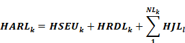
The hourly-adjusted recovery load for the kth water heating system is calculated as:
Equation 3
where
HSEUk = Hourly standard end use at all use points (Btu), see Equation 4
HRDLk = Hourly recirculation distribution loss (Btu), see Equation 15
HRDLk is non-zero only for multi-family central water heating systems
NLk = Number of unfired or indirectly-fired storage tanks in the kth system
HJLl = Tank surface losses of the lth unfired tank of the kth system (Btu), see Equation 45
Equation 4 calculates the hourly standard end use (HSEU). The heat content of the water delivered at the fixture is the draw volume in gallons (GPH) times the temperature rise ∆T (difference between the cold water inlet temperature and the hot water supply temperature) times the heat required to elevate a gallon of water 1 ºF (the 8.345 constant).

where
HSEUk = Hourly standard end use (Btu)
GPHk = Hourly hot water consumption (gallons) from Equation 2
Equation 5 calculates the distribution loss multiplier (DLM) which combines the standard distribution loss multiplier (SDLM), which depends on the floor area of the dwelling unit and the distribution system multiplier (DSM).
Equation 5
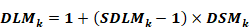
where
DLMk = Distribution loss multiplier (unitless)
SDLMk = Standard distribution loss multiplier (unitless), see Equation 6
DSMk = Distribution system multiplier (unitless), see Section 3.2Several relationships depend on CFAk, the floor area served (see below).
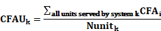
Equation 6 calculates the standard distribution loss multiplier (SDLM) based on dwelling unit floor area. Note that in Equation 6, that floor area CFAUk is capped at 2500 ft2--without that limit, Equation 6 produces unrealistic SDLMk values for large floor areas.
Equation 6
SDLMk = 1.0032 = 0.0001864 x CFAUk – 0.00000002165 x CFAUk2
where
SDLMk=Standard distribution loss multiplier (unitless).
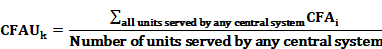
CFAUk=Dwelling unit conditioned floor area (ft2) served by the kth system, calculated using methods specified in Equation 7.
Single dwelling unit,
Equation 7-Method WH-CFAU

For multiple dwelling units served by a central system:
Alternatively, if the system-to-unit relationships not known:
Note: “Method” designations are invariant tags that facilitate cross-references from comments in implementation code.
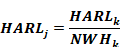
When a water heating system has more than one water heater, the total system load is assumed to be shared equally by each water heater, as shown in Equation 8.
Equation 8
where
HARLj =Hourly adjusted recovery load for the jth water heater of the kth system (Btu)
HARLk =Hourly adjusted total recovery load for the kth system (Btu)
NWHk=The number of water heaters in the kth system
The distribution system multiplier (DSM, unitless) is an adjustment for alternative water heating distribution systems within the dwelling unit. A value of 1.00 for “standard” distribution systems, defined as a non-recirculating system with the following mandatory requirements:
The full length of distribution piping is insulated in accordance with Section 150.0(j)2.
Equation 9
DSMk = ADSMk x CFk
Where
ADSMk = Assigned Distribution System Multiplier, see below.
CFk = Compactness factor (unitless), default value is 1.0; calculated according to Section 5.6.2.4 of the Residential Compliance Manual.
ADSM values for alternative distribution systems are given in Table B-1. Improved ADSM values are available for cases where voluntary HERS inspections are completed, as per the eligibility criteria shown in Reference Residential Appendix RA4.4. Detailed descriptions of all of the distribution system measures are found in Residential Appendix RA 4.4.
|
Assigned Distribution System Multiplier (ADSM) |
System Type 1 and 2 |
System Type 3 and 4 | |
|
No HERS Inspection Required |
|
|
|
|
Trunk and Branch -Standard (STD) |
1.0 |
Yes |
Yes |
|
|
|
|
|
|
Central Parallel Piping (PP) |
1.10 |
Yes |
|
|
Point of Use (POU) |
0.30 |
Yes |
|
|
Recirculation: Non-Demand Control Options (R-ND) |
9.80* |
Yes |
|
|
Recirculation with Manual Demand Control (R-DRmc) |
1.75* |
Yes |
|
|
Recirculation with Motion Sensor Demand Control (R-DRsc) |
2.60* |
Yes |
|
|
Optional Cases: HERS Inspection Required |
|
|
|
|
Pipe Insulation (PIC-H) |
0.85 |
Yes |
Yes |
|
Central Parallel Piping with 5’ maximum length (PP-H) |
1.00 |
Yes |
|
|
Compact Design (CHWDS-H) |
0.70 |
Yes |
|
|
Recirculation with Manual Demand Control (R-DRmc-H) |
1.60* |
Yes |
|
|
Recirculation with Motion Sensor Demand Control (RDRsc-H) |
2.40* |
Yes |
|
|
*Recirculation ADSMs reflect impact of reduced hot water consumption associated with recirculation systems. | |||
The water heater inlet temperature is assumed to vary daily and depends on mains water temperature, drain water heat recovery, and solar preheating.
For each day of the year, Tmains is calculated as follows:
Equation 10

where
Tavg31 = Outdoor dry-bulb temperature averaged over all hours of the previous 31 days (note for January days, weather data from December will be used)
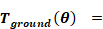
Tground = Ground temperature (°F ) for current day of year, calculated using .Equation 11
For each day ( = 1 TO 365
Equation 11

where
TyrAve = average annual temperature, °F
TyrMin = the lowest average monthly temperature, °F
TyrMax = the highest average monthly temperature, °F
PB = 365
PO = 0.6
DIF = 0.025 ft2/hr
BETA = SQR(π/(DIF*PB*24))*10
XB = EXP(-BETA)
CB = COS( BETA)
SB = SIN( BETA)
GM = SQR((XB*XB - 2.*XB*CB + 1)/(2.*BETA*BETA))
PHI = ATN((1.-XB*(CB+SB)) / (1.-XB*(CB-SB)))
The water heater inlet temperature, Tinlet, is calculated as follows:
Equation 12

where
SSFk =Solar savings fraction for kth system (see below), unitless
ΔTdwhr = Water temperature increase due to drain water heat recovery, °F (0 if no DWHR). See Section B4.3.
Ts = Hot water supply temperature
All water heaters in a water heating system are assumed to have the same Tinlet .
The hourly solar savings fraction for the kth water heating system, SSFk, is the fraction of the total water heating load that is provided by solar hot water heating. The annual average value for SSF is provided from the results generated by the Energy Commission approved calculations approaches for the OG-100 and OG-300 test procedure. A Commission-approved method shall be used to convert the annual average value for SSF to hourly SSFk values for use in compliance calculations.
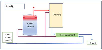
Drain water heat recovery (DWHR) devices are heat exchangers that transfer heat from warm drain water to incoming cold (mains) water. These operate on draws where supply and drain flow are simultaneous – for example, showers (as opposed to dishwashers). In CBECC-Res, only shower draws support DWHR. Several plumbing configurations are possible.
|
Heat exchanger output is connected to both shower water heater cold sides. Best performance.
Designated “Equal flow” because the heat exchanger potable and drain sides have the same flow (assuming no simultaneous other draws) |
|
|
Heat exchanger output is connected to water heater cold side. Designated “Unequal flow – water heater” |
|
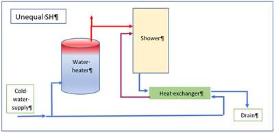
|
Heat exchanger output is connected to shower cold side. Easiest to construct. Designated “Unequal flow – shower” |
|
In practice, there are many combination plumbing configurations that are possible. For example, only some showers may drain via DWHR devices or more than one shower may drain via a shared DHWR device. CBECC-Res input structure allows flexible specification of such arrangements.
The drain water heat recovery temperature increase, ΔTdwhr, is modeled within CSE using effectiveness derived using correlations presented in:
• Drain Water Heat Recovery – Final Report. Measure Number: 2019-RES-DHW2-F. Available at http://title24stakeholders.com/wp-content/uploads/2017/09/2019-T24-CASE-Report_DWHR_Final_September-2017.pdf
• Explanation of Drain Water Heat Recovery Calculations. NegaWatt Consulting. Dec. 13, 2017.
DWHR is supported only for shower draws. Based on experimental data, the effectiveness correlation is function of potable water flow rate, potable water entering temperature, and drain water flow rate, as shown here:
Equation 13
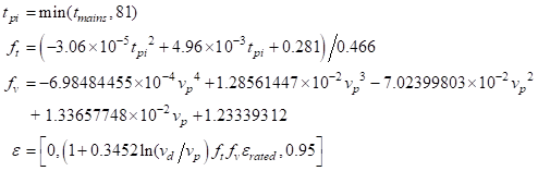
where
tpi = DWHR potable water inlet temperature, °F
vp = Potable volume flow rate, gpm. vp depends on the plumbing configuration and is various combinations of the fixture hot water draw, the fixture cold water draw, and the total hot water draw.
vd = Drain volume flow rate, gpm. The drain volume is equal to the total (mixed) draws of fixture(s) evaluated not including fdur (see ) since no heat can be recovered during warmup.
ε = DWHR effectiveness under current conditions, unitless
εrated = DWHR rated effectiveness = efficiency/100, rated at CSA B55.1 conditions (9.5 lpm, equal flow)
The effectiveness, ε, is used to calculate the potable water temperature increase.
Equation 14
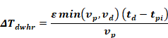
where
td = DWHR drain-side entering temperature, °F = shower use temperature (105 °F) – 4.6 °F. The latter adjustment approximates heat loss between the shower and the DWHR device.
Note that in this model with some plumbing configurations, effectiveness depends on vp and vp depends of effectiveness. An iterative solution technique is required to find consistent conditions.
When only some shower fixtures within a dwelling unit drain via a DWHR system, savings are assumed to be proportional to the number of included shower fixtures. This is implemented by assigning shower draws in rotation to DWHR or non-DWHR arrangements.