
All of the equipment efficiency requirements are mandatory measures.
The mandatory requirements for mechanical equipment must be included in the system design, whether the overall building compliance is the prescriptive or performance approach. These features are cost effective over a wide range of building types and mechanical systems.
Most mandatory features for equipment efficiency are requirements for the manufacturer. It is the responsibility of the designer to specify products in the building design that meet these requirements. Manufacturers of central air conditioners and heat pumps, room air conditioners, package terminal air conditioners, package terminal heat pumps, spot air conditioners, computer room air conditioners, central fan-type furnaces, gas space heaters, boilers, pool heaters and water heaters are regulated through the Title 20 Appliance Efficiency Regulations. Manufacturers must certify to the Energy Commission that their equipment meets or exceeds minimum standards. The Commission maintains a database which lists the certified equipment found at: www.energy.ca.gov/appliances/database
Additionally, manufacturers of low leakage air-handling units must certify to the Energy Commission that the air-handler unit meets the specifications in Reference Appendices JA9.
Mechanical equipment must be certified by the manufacturer as complying with the mandatory requirements in the following sections:
1. §110.0 - Mandatory Requirements for Systems and Equipment Certification
2. §110.1 - Mandatory Requirements for Appliances.
3. §110.2|topic=SECTION 110.2 – MANDATORY REQUIREMENTS FOR SPACE-CONDITIONING EQUIPMENT - Mandatory Requirements for Space-Conditioning Equipment
a. Efficiency
b. Gas- and Oil-Fired Furnace Standby Loss Controls
c. Low Leakage Air-Handling Units
4. §110.3 - Mandatory Requirements for Service Water Heating Systems and Equipment
a. Certification by Manufactures
b. Efficiency
5. §110.4 - Mandatory Requirements for Pool and Spa Systems and Equipment
a. Certification by Manufactures
6. §110.5 - Natural Gas Central Furnaces, Cooking Equipment, and Pool and Spa Heaters: Pilot Lights Prohibited
Mechanical equipment must be specified and installed in accordance with sections:
1. §110.2|topic=SECTION 110.2 – MANDATORY REQUIREMENTS FOR SPACE-CONDITIONING EQUIPMENT - Mandatory Requirements for Space Conditioning Equipment
a. Controls for Heat Pumps with Supplementary Electric Resistance Heaters
b. Thermostats
c. Open and Closed-Circuit Cooling Towers (blowdown control)
2. §110.3 - Mandatory Requirements for Service Water Heating Systems and Equipment
3. §110.12 – Mandatory Requirements for Demand Management
4. §120.1 - Requirements for Ventilation and Indoor Air Quality
5. §120.2 - Required Controls for Space Conditioning Systems (see Section 4.5)
a. Occupant Controlled Smart Thermostats (OCST)
b. Direct Digital Controls (DDC)
c. Optimum Start/Stop Controls
d. Economizer Fault Detection and Diagnostics
6. §120.3 - Requirements for Pipe Insulation
7. §120.4 - Requirements for Air Distribution Ducts and Plenums
8. §120.5 - Required Nonresidential Mechanical System Acceptance
9. 120.10 – Fan Energy Index
All space conditioning equipment installed in a nonresidential building, subject to these regulations, must be certified as meeting certain minimum efficiency and control requirements. These requirements are contained in §110.2|topic=SECTION 110.2 – MANDATORY REQUIREMENTS FOR SPACE-CONDITIONING EQUIPMENT and vary based on the type and capacity of the equipment. Tables 110.2-A through 110.2-N list the minimum equipment efficiency requirements for the 2022 Energy Code.
Where more than one efficiency standard or test method is listed, the requirements of both shall apply. For example, air-cooled air conditioners have an EER requirement for full-load operation and an IEER for part-load operation. The air conditioner must have both a rated EER and IEER equal to or higher than that specified in the Energy Code at the specified Air-Conditioning, Heating, and Refrigeration Institute (AHRI) standard rating conditions. Where equipment serves more than one function, it must comply with the efficiency standards applicable to each function.
When there is a requirement for equipment rated at its “maximum rated capacity” or “minimum rated capacity,” the proper capacity shall be maintained by the controls during steady state operation. For example, a boiler with high/low firing must meet the efficiency requirements when operating at both its maximum capacity and minimum capacity.
Exceptions exist to the listed minimum efficiency for specific equipment. The first exception applies to water-cooled centrifugal water-chilling packages not designed for operation at ANSI/AHRI Standard 550/590 test conditions, which are:
a. 44 degrees Fahrenheit (F) leaving chilled water temperature
b. 85 degrees F entering condenser water temperature
c. Three gallons per minute per ton condenser water flow
Packages not designed to operate at these conditions must have maximum adjusted full load and NPLV ratings, which can be calculated in kW/ton, using Equation 4-1 and Equation 4-2.
Equation 4-2
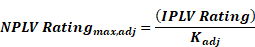
The values
for the Full Load and IPLV ratings are found in . 


 .Equation
4-6.
.Equation
4-6.
 u
u


Where:
LvgCond = Full load leaving condenser fluid temperature (°F)
LvgEvap = Full load leaving evaporator fluid temperature (°F)
Equation 4-7

Where:
LvgEvap = Full load leaving evaporator fluid temperature (°F)
The maximum adjusted full load and NPLV rating values are only applicable for centrifugal chillers meeting all of the following full-load design ranges:
1. Minimum leaving evaporator fluid temperature: 36 degrees F
2. Maximum leaving condenser fluid temperature: 115 degrees F
3. LIFT greater than or equal to 20 degrees F and less than or equal to 80 degrees F
Centrifugal chillers designed to operate outside of these ranges are not covered by this exception and therefore have no minimum efficiency requirements.
Exception 2 are for positive displacement (air-cooled and water-cooled) chillers with a leaving evaporator fluid temperature higher than 32 degrees F. These equipment shall comply instead with Table 110.2-D in the Energy Code when tested or certified with water at standard rating conditions, per the referenced test procedure.
Exception 3 is for equipment primarily serving refrigerated warehouses or commercial refrigeration systems. These systems must comply with the efficiency requirements of Energy Code §120.6(a)|topic=(a) Mandatory Requirements for Refrigerated Warehouses or (b). For more information, see Chapter 10.
§110.2|topic=SECTION 110.2 – MANDATORY REQUIREMENTS FOR SPACE-CONDITIONING EQUIPMENT and §110.3.
Manufacturers of any appliance or equipment regulated by Section 1601 of the Appliance Efficiency Regulations are required to comply with the certification and testing requirements of Section 1608(a) of those regulations. This includes being listed in the Modernized Appliance Efficiency Database System.
Equipment not covered by the Appliance Efficiency Regulations, for which there is a minimum efficiency requirement in the Energy Code, cannot be installed unless the required efficiency data is listed and verifiable in one of the following:
1. The Energy Commission's database of certified appliances available at: www.energy.ca.gov/appliances/.
2. An equivalent directory published by a federal agency.
3. An approved trade association directory as defined in Title 20 California Code of Regulations, Section 1606(h) such as the Air Conditioning, Heating and Refrigeration Institute (AHRI) Directory of Certified Products. This information is available at www.ahridirectory.org.
4. The Home Ventilating Institute (HVI) certified products directory available at www.hvi.org.
§110.2(b)|topic=(b) Controls for Heat Pumps with Supplementary Electric Resistance Heaters.
The Energy Code discourage use of electric resistance heating when an alternative method of heating is available. Heat pumps may contain electric resistance heat strips which act as a supplemental heating source. If this type of system is used, then controls must be put in place to prevent the use of the electric resistance supplementary heating when the heating load can be satisfied with the heat pump alone. The controls must set a cut-on temperature for compressor heating higher than the cut-on temperature for electric resistance heating. The cut-off temperature for compression heating must also be set higher than the cut-off temperature for electric resistance heating.
Exceptions exist for these control requirements if one of the following applies:
1. The electric resistance heating is for defrost and during transient periods such as start-ups and following room thermostat set points (or another control mechanism designed to preclude the unnecessary operation).
2. The heat pump is a room air-conditioner heat pump.
All heating or cooling systems are required to have a thermostat with setback capability and is capable of at least four set points in a 24-hour period. In the case of a heat pump, the control requirements of Section 4.2.4 must also be met.
In addition, per §120.2(b)4, the thermostats on all single zone air conditioners and heat pumps must comply with the demand responsive control requirements of Section 110.12(a), also known as the Occupant controlled Smart Thermostat (OCST). See Appendix D of this compliance manual for guidance on compliance with demand responsive control requirements.
Exceptions to §120.2(b)4, setback thermostat and OCST requirements:
1. Systems serving zones that must have constant temperatures to protect a process or product (e.g., a laboratory or a museum).
1. The following HVAC systems are exempt:
a. Gravity gas wall heaters
b. Gravity floor heaters
c. Gravity room heaters
d. Non-central electric heaters
e. Fireplaces or decorative gas appliance
f. Wood stoves
g. Room air conditioners
h. Room heat pumps
i. Packaged terminal air conditioners
j. Packaged terminal heat pumps
In most cases setup and setback are based on time of day only. However, see Section 4.6.1.4, Shut-off and Temperature Setup/Setback which describes those applications where occupancy sensing is also required to trigger setup and setback periods and shutting off ventilation air.
§110.2(d)|topic=(d) Gas-Fired and Oil-Fired Furnace Standby Loss Controls.
Forced air gas- and oil-fired furnaces with input ratings greater than or equal to 225,000 Btu/h are required to have controls and designs that limit their standby losses:
1. Either an intermittent ignition or interrupted device (IID) is required. Standing pilot lights are not allowed.
2. Either a power venting or a flue damper is required. A vent damper is an acceptable alternative to a flue damper for furnaces where combustion air is drawn from the conditioned space.
Any furnace with an input rating greater than or equal to 225,000 Btu/h that is not located within the conditioned space must have jacket losses not exceeding 0.75 percent of the input rating. This includes electric furnaces and fuel-fired units.
All open and closed-circuit cooling towers with rated capacity of 150 tons or greater must have a control system that maximizes the cycles of concentration based on the water quality conditions. If the controls system is conductivity based, then the system must automate bleed and chemical feed based on conductivity. The installation criteria for the conductivity controllers must be in accordance with the manufacturer’s specifications to maximize accuracy. If the control system is flow based, then the system must be automated in proportion to metered makeup volume, metered bleed volume, and recirculating pump run time (or bleed time).
The makeup water line must be equipped with an analog flow meter and an alarm to prevent overflow of the sump in the event of water valve failure. The alarm system may send an audible signal or an alert through an energy management control system (EMCS).
Drift eliminators are louvered or comb-like devices that are installed at the top of the cooling tower to capture air stream water particles. These drift eliminators are now required to achieve drift reduction to 0.002 percent of the circulated water volume for counter-flow towers and 0.005 percent for crossflow towers.
Additionally, maximum achievable cycles of concentration must be calculated with an Energy Commission approved calculator based on local water quality conditions (which is reported annually by the local utility) and a Langelier Saturation Index (LSI) of 2.5 or less. The maximum cycles of concentration must be cataloged in the mechanical compliance documentation and reviewed and approved by the Professional Engineer (P.E.) of record. Energy Commission compliance document NRCC-MCH-E has a built-in calculator. An approved excel file LSIcalculator is located on the Energy Commission’s website.
The website address for the excel calculator is: http://www.energy.ca.gov/title24/2013standards/documents/maximum_cycles_calculator.xls
The website address for the NRCC-MCH-06 is:
http://www.energy.ca.gov/2015publications/CEC-400-2015-033/appendices/forms/NRCC/
Pilot lights are prohibited in the following circumstances:
3. Fan type central furnaces. This includes all space-conditioning equipment that distributes gas-heated air through duct work §110.5(a). This prohibition does not apply to radiant heaters, unit heaters, boilers or other equipment that does not use a fan to distribute heated air.
4. Household cooking appliances, unless the appliance does not have an electrical connection, and the pilot consumes less than 150 Btu/h §110.5(b).
5. Pool and spa heaters §110.5(c) and §110.5(d) respectively.
6. Indoor and outdoor fireplaces §110.5(e).
Example 4-1
Question
If a 15 ton (180,000 Btu/h) air-cooled packaged AC unit with a gas furnace rated at 260,000 Btu/h maximum heating capacity has an EER of 10.9, an IEER of 12.3, and a heating thermal efficiency of 78 percent, does it comply?
Answer
No. While the cooling side appears to not comply because both the EER and IEER are less than the values listed in Table 4-1, the EER and IEER values in the table are for units with electric heat. Footnote b reduces the required EER and IEER by 0.2 for units with heating sections other than electric resistance heat. Since this unit has gas heat, the EER requirement is actually 10.8 and the IEER requirement is 12.2, this unit complies with the cooling requirements. The 0.2 deduction provided in Table 4-1 and Table 4-2 compensates for the higher fan power required to move air through the heat exchanger.
From Table 4-1, the heating efficiency must be at least 80 percent thermal efficiency. This unit has a 78 percent thermal efficiency and does not comply with the heating requirements; therefore, the entire unit does not comply since it’s a packaged unit.
Example 4-2
Question
A 500,000 Btu/h gas-fired hot water boiler with high/low firing has a full load combustion efficiency of 82 percent, 78 percent thermal efficiency and a low-fire combustion efficiency of 80 percent. Does the unit comply?
Answer
No. Per Table 4-11, the thermal efficiency must be greater than 80 percent. This boiler’s thermal efficiency is 78 percent (less than 80 percent), so it doesn’t comply.
Example 4-3
Question
A 300-ton water-cooled centrifugal chiller is designed to operate at 44 degrees F chilled water supply, 90 degrees F condenser water return and 3 gpm/ton condenser water flow. What is the maximum allowable full load kW/ton and NPLV?
Answer
As the chiller is centrifugal and is designed to operate at a condition different from AHRI Standard 550/590 standard rating conditions (44 degrees F chilled water supply, 85 degrees F condenser water return, 3 gpm/ton condenser water flow), the appropriate efficiencies can be calculated using the Kadj equations.
From Table 4-4 (Equipment Type: water cooled, electrically operated, centrifugal; Size Category: ≥ 300 tons and < 600 tons), this chiller at AHRI rating conditions is required to have a maximum full load efficiency of 0.560 kW/ton and a maximum IPLV of 0.520 kW/ton for Path A and a maximum full load efficiency of 0.595 kW/ton and a maximum IPLV of 0.390 kW/ton for Path B.
The Kadj is calculated as follows:
LIFT = LvgCond – LvgEvap = 90F-44F = 46F
A = (0.00000014592 x (46)4) – (0.0000346496 x (46)3)+ (0.00314196 x (46)2) – (0.147199 x (46)) + 3.9302=1.08813
B = (0.0015 x 44) + 0.934 = 1.000
Kadj = A x B = 1.08813
For compliance with Path A, the maximum Full load kW/ton = 0.560 / 1.08813 = 0.515 kW/ton and the maximum NPLV= 0.520 / 1.08813 = 0.478 kW/ton
For compliance with Path B the maximum Full load kW/ton = 0.595 / 1.08813 = 0.547 kW/ton and the maximum NPLV= 0.390 / 1.08813 = 0.358 kW/ton
To meet the mandatory measures of 4.2.2 (Energy Code §110.2|topic=SECTION 110.2 – MANDATORY REQUIREMENTS FOR SPACE-CONDITIONING EQUIPMENT) the chiller can comply with either the Path A or Path B requirement (footnote b in Table 4-4). To meet the prescriptive requirement of 4.6.2.8 (Energy Code §140.4(i)) the chiller would have to meet or exceed the Path B requirement.
Example 4-4
Question
A 300 ton water-cooled chiller with a screw compressor that serves a thermal energy storage system is designed to operate at 34 degrees F chilled water supply, 82 degrees F condenser water supply and 94 degrees F condenser water return, does it have a minimum efficiency requirement and if so, what is the maximum full load kW/ton and NPLV?
Answer
As the chiller is positive displacement (screw and scroll compressors are positive displacement) and is designed to operate at a chilled water temperature above 32 degrees F it does have a minimum efficiency requirement per 4.2.2 (Exception 2 to §110.2(a)). From Table 4-4(Equipment Type: water cooled, electrically operated, positive displacement; Size Category: ≥ 300 tons) this chiller at AHRI rating conditions is required to have a maximum full load efficiency of 0.610 kW/ton and a maximum IPLV of 0.520 kW/ton for Path A and a maximum full load efficiency of 0.625 kW/ton and a maximum IPLV of 0.410 kW/ton for Path B.
The Kadj is calculated as follows:
LIFT = LvgCond – LvgEvap = 94F-34F
= 60F
A = (0.00000014592 x (60)4) – (0.0000346496 x (60)3 )+ (0.00314196 x
(60)2) – (0.147199 x *(60)) + 3.9302=0.81613
B = (0.0015 x 34) + 0.934 =
0.98500
Kadj = A x B = 0.80388
For compliance with Path A, the maximum Full load kW/ton = 0.610 / 0.80388 = 0.759 kW/ton and the maximum NPLV= 0.520 / 0.80388 = 0.647 kW/ton. For compliance with Path B the maximum Full load kW/ton = 0.625 / 0.80388 = 0.777 kW/ton and the maximum NPLV= 0.410 / 0.80388 = 0.510 kW/ton. To meet the mandatory measures of 4.2.2 (Energy Code §110.2|topic=SECTION 110.2 – MANDATORY REQUIREMENTS FOR SPACE-CONDITIONING EQUIPMENT) the chiller can comply with either the Path A or Path B requirement (footnote b in Table 4-4). To meet the prescriptive requirement of 4.6.2.8 (Energy Code §140.4(i)) the chiller would have to meet or exceed the Path B requirement.
Example 4-5
Question
Are all cooling towers required to be certified by CTI?
Answer
No. Per footnote d in Table 4-7, field-erected cooling towers are not required to be certified. Factory-assembled towers must either be CTI-certified or have their performance verified in a field test (using ATC 105) by a CTI-approved testing agency. Furthermore, only base models need to be tested; options in the airstream, like access platforms or sound traps, will derate the tower capacity by 90 percent of the capacity of the base model or the manufacturer’s stated performance, whichever is less.
Example 4-6
Question
Are there any mandatory requirements for a water-to-water plate-and-frame heat exchanger?
Answer
Yes, Table 4-6 requires that it be rated per ANSI/AHRI 400. This standard ensures the accuracy of the ratings provided by the manufacturer.
A commercial boiler is a type of boiler with a capacity (rated maximum input) of 300,000 Btu/h or more and serving a space heating or water heating load in a commercial building.
A. Combustion air positive shut off shall be provided on all newly installed commercial boilers as follows:
1. All boilers with an input capacity of 2.5 MMBtu/h (2,500,000 Btu/h) and above, in which the boiler is designed to operate with a non-positive vent static pressure. This is sometimes referred to as natural draft or atmospheric boilers. Forced draft boilers, which rely on a fan to provide the appropriate amount of air into the combustion chamber, are exempt from this requirement.
2. All boilers where one stack serves two or more boilers with a total combined input capacity per stack of 2.5 MMBtu/h (2,500,000 Btu/h). This requirement applies to natural draft and forced-draft boilers.
Combustion air positive shut off is a means of restricting air flow through a boiler combustion chamber during standby periods and is used to reduce standby heat loss. A flue damper and a vent damper are two examples of combustion air positive shut-off devices.
Installed dampers can be interlocked with the gas valve so that the damper closes and inhibits air flow through the heat transfer surfaces when the burner has cycled off, thus reducing standby losses. Natural draft boilers receive the most benefit from draft dampers because they have less resistance to airflow than forced draft boilers. Forced draft boilers rely on the driving force of the fan to push the combustion gases through an air path that has relatively higher resistance to flow than in a natural draft boiler. Positive shut off on a forced draft boiler is most important on systems with a tall stack height or multiple boiler systems sharing a common stack.
B. Boiler combustion air fans with motors 10 horsepower or larger shall meet one of the following for newly installed boilers:
1. The fan motor shall be driven by a variable speed drive
2. The fan motor shall include controls that limit the fan motor demand to no more than 30 percent of the total design wattage at 50 percent of design air volume
Electricity savings result from run time at part-load conditions. As the boiler firing rate decreases, the combustion air fan speed can be decreased.
C. Newly installed boilers with an input capacity of 5 MMBtu/h (5,000,000 Btu/h) and greater shall maintain stack-gas oxygen concentrations at less than or equal to 5 percent by volume on a dry basis over firing rates of 20 percent to 100 percent. Combustion air volume shall be controlled with respect to firing rate or measured flue gas oxygen concentration. Use of a common gas and combustion air control linkage or jack shaft is prohibited.
Boilers with steady state full-load thermal efficiency of 90 percent or higher are exempt from this requirement.
One way to meet this requirement is with parallel position control. Boilers mix air with fuel (usually natural gas although sometimes diesel or oil) to supply oxygen during combustion. Stoichiometric combustion is the ideal air/fuel ratio where the mixing proportion is correct, the fuel is completely burned, and the oxygen is entirely consumed. Boilers operate most efficiently when the combustion air flow rate is slightly higher than the stoichiometric air-fuel ratio. However, common practice almost always relies on excess air to ensure complete combustion, avoid unburned fuel and potential explosion, and prevent soot and smoke in the exhaust. The drawbacks of excess air are increased stack heat loss and reduced combustion efficiency.
Parallel positioning controls optimize the combustion excess air based on the firing rate of the boiler to improve the combustion efficiency of the boiler. It includes individual servo motors allowing the fuel supply valve and the combustion air damper to operate independently of each other. This system relies on preset fuel mapping (i.e., a pre-programmed combustion curve) to establish proper air damper positions (as a function of the fuel valve position) throughout the full range of burner fire rate. Developing the combustion curve is a manual process. It is performed in the field with a flue-gas analyzer in the exhaust stack, determining the air damper positions as a function of the firing rate/fuel valve position. Depending on the type of burner, a more consistent level of excess oxygen can be achieved with parallel position compared to single-point positioning control with parallel positioning, the combustion curve is developed at multiple points (firing rates), typically 10 to 25 points. Parallel positioning controls allow excess air to remain relatively low throughout a burner’s firing range. Maintaining low excess air levels at all firing rates provides significant fuel and cost savings while still maintaining a safe margin of excess air to insure complete combustion.
The other method of control of combustion air volume is by measuring the flue gas oxygen concentration to optimize combustion efficiency. This method of control commonly called is oxygen trim control and can provide higher levels of efficiency than parallel positioning controls based only on firing rate as O2 trim it can also account for relative humidity of the combustion air. This control strategy relies on parallel positioning hardware and software as the basis but takes it a step further to allow operation closer to stoichiometric conditions. Oxygen trim control converts parallel positioning to a closed-loop control configuration with the addition of an exhaust gas analyzer and proportional-integral-derivative (PID) controller. This strategy continuously measures the oxygen content in the flue gas and adjusts the combustion air flow, thus continually tuning the air-fuel mixture.
D. Gas-fired hot water boiler systems with capacity between 1 and 10 million Btu/h, installed in newly constructed commercial buildings, shall have a weighted thermal efficiency of 90 percent. In order to achieve a thermal efficiency at or over 90 percent, all or some of the boilers must have condensing capability. These high efficiency boilers are referred to as condensing products because they can condense moisture out of flue gas, recovering latent heat from water vapor. Boilers within the same building but on separate loops are not considered to be a part of the same system. Weighted thermal efficiencies are calculated based off the input each boiler provides to the total system capacity.
Boiler systems in Climate Zones 7, 8, and 15 are exempted from this requirement.
Additional requirements for the hot water distribution systems served by these boilers help optimize condensing capabilities.
•First, space heating coils and heat exchangers must be sized so that under design conditions the return temperature of the hot water to the boilers is 120°F or less. Condensing operation requires a sufficient difference in temperatures between the inlet and outlet water.
•Second, hot water space heating systems are designed so that under all conditions the return water entering the boiler(s) must be 120°F or less, or flow rates for supply hot water that recirculates directly into the return system must be no greater than 20 percent of the design flow of the operating boiler. This flow rate requirement increases the likelihood that the boiler system will operate in the condensing range by increasing the amount of time the heating medium, water, contacts the heat exchanger.
There are three exceptions to this condensing requirement. These exceptions remove the following boilers from the thermal efficiency requirements: space heating boilers installed in individual dwelling units, and space heating boilers where 25 percent of the capacity is provided by on-site renewable energy (wind, photovoltaics , solar thermal) or recovered energy (heat recovery chiller, condenser desuperheater, refrigeration heat recovery etc.). Additionally, gas boilers with input capacity of less than 300,000 Btu/h do not need to meet the efficiency requirements and are not included in the calculation of system input or efficiency.
Example 4-6
Question
If I have the following 4 boilers, how do I calculate weighted average thermal efficiency? Boiler 1 with capacity 500,000 Btu/h; Boiler 2 with capacity 600,000 Btu/h and serving an individual dwelling unit; Boiler 3 with capacity 250,000 Btu/h; Boiler 4 with capacity 750,000 Btu/h. Boiler 1 has thermal efficiency of 90%, Boiler 2 has a TE of 87%, Boiler 3 has a TE of 95%, and Boiler 4 has a TE of 95%.
Answer: Since Boiler 2 serves an individual dwelling unit, it is not included in the weighted efficiency calculation. Similarly, since Boiler 3 has a capacity below 300,000 Btu/h, it is not included either. To calculate the weighted average thermal efficiency of boilers 1 and 4, multiply both boilers’ thermal efficiency by their capacity, add the two values together, and divide by the combined capacity. So, multiply 90%TE and 500,000 Btu/h and multiply 95%TE and 750,000 Btu/h. Add these two products together and divide by 1,250,000 Btu/h. The result is a weighted thermal efficiency of 93%.