
§150.0(o), §150.2(a)1C, and §150.2(a)2C.
This section provides basic concepts and context to help navigate the mandatory requirements for exhaust fans in bathrooms and kitchens, and continuous low-cfm indoor-outdoor (I-O) air exchange in single-family homes.
The Energy Code requirement for mechanical ventilation of homes is a health and safety priority, not a building energy efficiency measure. Efficient homes are more airtight for comfort and efficiency, which makes it both easier and more important to use a small I-O fan to control air exchange.
Because mechanical ventilation is a continuous electrical end use in homes, energy efficiency is a factor to consider when selecting a ventilation system. Other factors include quiet operation, outdoor air filtration, and indoor air distribution. The Energy Code sets minimum standards for airflow, noise, ducting, and controls.
Unlike central forced-air space conditioning systems that heat, cool, mix and re-circulate indoor air to maintain comfort, the purpose of continuous mechanical ventilation is to ensure adequate I-O air exchange whenever windows are closed.
Central space conditioning systems use supply and return ductwork to move large amounts of air (over 1,000 cfm) as needed in response to a thermostat. Whole-dwelling mechanical ventilation systems use smaller (about 100 cfm) fans to continually exchange air through supply and/or exhaust ventilation ductwork.
Residential mechanical ventilation is a means to another end, which is acceptable indoor air quality (IAQ) for occupants. Energy Code-compliant ventilation systems can be expected to control the common types and levels of residential indoor air pollutants—moisture, odors, and volatile organic chemicals (VOCs). However, they cannot protect occupants from tobacco smoke or other high-polluting events that create excess moisture, odors, or VOCs in the home. In other words, because they cannot account for all the variables of occupant lifestyle and behavior, these ventilation systems do not guarantee good IAQ.
When possible, indoor air pollutants should be controlled at their source. That is the purpose of exhaust fans in bathrooms and kitchens, which occupants operate as needed. Also called local exhaust fans or spot fans, they are the best way to eliminate excess indoor moisture – operable windows are no longer sufficient.
ASHRAE Standard 62.2–Ventilation for Acceptable Indoor Air Quality in Residential Buildings recognizes the need for controlled mechanical outdoor air supply in homes that are built tight for efficient space conditioning. Infiltration, or uncontrolled air leakage through the building, is highest during winter and lowest in mild weather, and too inconsistent to rely on for air exchange.
California’s 2008 Energy Code adopted Standard 62.2-2007 with exceptions, and the 2013 Energy Code began requiring HERS field verification of airflow rates of residential I-O ventilation systems installed to meet this requirement. 2022 Energy Code incorporate updated versions of Standard 62.2 and extend its requirements to multifamily and high-rise residential buildings.
Standard 62.2 requires two residential mechanical ventilation functions:
•Local exhaust fans in bathrooms and kitchens to remove most occupant-generated moisture and odors where and when they are generated.
•Whole-dwelling ventilation systems to automatically ensure an adequate amount of I-O air exchange year-round, regardless of window operation.
It also discusses the need for tightening building envelopes and preventing habitable spaces from drawing air from polluted spaces such as garages, attics, crawlspaces, adjacent dwellings, and other sources of outdoor air pollution.
Since the Energy Code requirement for mechanical ventilation is a continuous electrical end use in new homes, fan efficacy (in W/cfm fan flow) is one factor to consider when selecting a ventilation system.
There are three basic ways to meet the whole-dwelling ventilation requirement.
•Exhaust-only systems remove indoor air and create some degree of negative indoor pressure (depressurization) that induces air infiltration of the building envelope through the paths of least resistance.
•Supply-only systems filter outdoor air from a known location before delivering it to a home; this creates some degree of positive pressure (pressurization) that can serve to both prevent infiltration and buffer against depressurization.
•Balanced ventilation systems use an exhaust fan and a supply fan that move approximately the same amount of air at the same time; these opposite airflows have little effect on indoor pressure, and cannot prevent the forces of wind, stack effect, and other fans from pressurizing or depressurizing a home.
Indoor pressures cannot be avoided. In fact, the tighter and more energy-efficient the building envelope, the higher indoor pressures can and will be. Airflow requires both a driving force and a pathway. Regardless of the degree of indoor pressure, infiltration cannot occur unless there are leakage sites or designated pathways for air to flow.
The building science principle “Build Tight, Ventilate Right” acknowledges that energy efficient homes require tight building envelopes that make it possible for a continuous low-cfm ventilation system to control indoor-outdoor air exchange.
Balanced systems do not create indoor pressure or neutralize indoor pressure. The advantage of a balanced mechanical ventilation system is the ability to incorporate an engineered heat exchanger core that passively transfers thermal energy between the outgoing exhaust airstream and incoming supply airstream. This reduces the cost of heating and cooling the incoming supply ventilation air. However, balanced heat or energy recovery ventilation (HRV, ERV) systems cannot recover heat from air that infiltrates the home and bypasses the system’s core.
The remainder of this section describes minimum requirements for residential mechanical ventilation, which can be readily exceeded or improved upon by:
•Using local exhaust fans as needed to remove moisture and odors.
•Using source control to minimize air pollutants within the building.
•Operating the whole-dwelling fan continuously to minimize VOC levels.
As residential buildings are tightened to improve energy performance, the dilution of indoor air through natural ventilation and infiltration has been reduced. As a result, the importance of controlling indoor pollutants and moisture generated and volatile organic compounds (VOCs) n homes has increased.
Energy Commission sponsored field research revealed that indoor concentrations of pollutants such as formaldehyde are higher than expected, and that many occupants do not open windows regularly for ventilation.
The Energy Code includes mandatory requirements for local mechanical exhaust and whole-dwelling unit mechanical ventilation to improve indoor air quality (IAQ) in homes and MERV 13 air filtration requirements for ventilation systems. As specified by §150.0(o), dwelling units must meet the requirements of ASHRAE Standard 62.2-2019 including Addenda v and d (ASHRAE 62.2), subject to the amendments specified in Section 150.0(o)1. A copy of this version of ASHRAE 62.2 may be obtained at the following URL:
https://www.techstreet.com/ashrae/standards/ashrae-62-2-2019?product_id=2087691
Opening and closing windows and continuous operation of central fan-integrated ventilation systems are not allowable options for meeting dwelling unit ventilation requirements. The requirements of ASHRAE Standard 62.2 focus on providing continuous dwelling unit mechanical ventilation, as well as local exhaust ventilation at known sources of pollutants or moisture, such as kitchens, bathrooms, and laundries. The California Air Resources Board (CARB) provides guidance for reducing indoor air pollution in homes by selecting low-VOC building materials, finishes, and furnishings. For more information, see the CARB Indoor Air Quality Guidelines:
http://www.arb.ca.gov/research/indoor/guidelines.htm
This section covers mandatory requirements for mechanical ventilation of homes, the process of compliance and enforcement, including HERS verifications, and requirements specified by ASHRAE 62.2 as amended in the Energy Code. Compliance with the whole-dwelling unit ventilation airflow specified in ASHRAE 62.2 is required in new dwelling units, in new dwelling units that are additions to an existing building except for junior accessory dwelling units, and in additions to existing dwelling units that increase the conditioned floor area of the existing dwelling unit by more than 1,000 square feet. Alterations to components of existing buildings that previously met any requirements of ASHRAE 62.2 must continue to meet requirements upon completion of the alteration(s).
The key requirements for most newly constructed buildings are summarized below:
1. A whole-dwelling unit mechanical ventilation system shall be provided. Typical solutions are described in Section 4.6.4 below. The airflow rate provided by the system shall be confirmed through field verification and diagnostic testing in accordance with the applicable procedures specified in RA3.7.
2. Kitchens and bathrooms must have local exhaust systems vented to outdoors.
3. Clothes dryer exhaust shall be vented to outdoors.
Additional indoor air quality design requirements include:
1. Ventilation air shall come from outdoors and shall not be transferred from adjacent dwelling units, garages, unconditioned attics, or crawl spaces.
2. Ventilation system controls shall be labeled, and the homeowner shall be provided with instructions on how to operate the system.
3. Combustion appliances shall be properly vented to outdoors and exhaust systems shall be designed to prevent back drafting.
4. Walls and openings between the house and attached garage shall be sealed or gasketed to prevent air exchange between the house and garage.
5. Habitable rooms shall have operable windows with a free opening area of at least 4 percent of the floor area.
6. Mechanical systems including space conditioning systems that supply air to habitable spaces shall have a MERV 13 or better filter and be designed to accommodate the air filter’s rated pressure drop at the designed airflow rate.
7. Dedicated outdoor air inlets that are part of the ventilation system design shall be located away from known sources of outdoor contaminants.
8. A carbon monoxide alarm shall be installed in each dwelling unit in accordance with NFPA Standard 720.
9. Air-moving equipment used to meet the whole-dwelling unit ventilation requirement and local exhaust requirement shall be rated for airflow and sound:
a. Whole-dwelling unit ventilation and continuously operating local exhaust fans must be rated at a maximum of 1.0 sone.
b. Demand-controlled local exhaust fans must be rated at a maximum of 3.0 sones.
c. Kitchen exhaust fans must be rated at a maximum of 3.0 sones at one or more airflow settings greater than or equal to 100 CFM.
d. Remotely located air-moving equipment (mounted outside habitable spaces) are exempt from the sound requirements provided there is at least 4 feet of ductwork between the remote fan and interior grille.
Compliance with ASHRAE 62.2 requirements must be verified by the enforcement agency, except for the following requirements that must be HERS verified in accordance with the procedures in Residential Appendix RA3.7:
•Whole-dwelling unit ventilation airflow rate
•HVI or AHAM ratings for kitchen local mechanical exhaust fan airflow or capture efficiency, and sound.
All applicable certificates of compliance, installation, and verification must be registered with an approved HERS Provider.
Title 24 Part 6 amendments to ASHRAE 62.2 do not require a blower door measurement when calculating the dwelling unit mechanical ventilation rate (Qfan). Instead, the Qfan calculation applies a default infiltration leakage rate of 2 ACH50 (air changes per hour at 50 Pascals). Blower door measurement of actual dwelling unit enclosure leakage is required only when performance compliance modeling uses an infiltration leakage rate less than 2 ACH50 - which requires HERS verification of enclosure leakage for energy compliance and for determining Qfan.
If a central heating/cooling system air-handler fan is used to ventilate the dwelling (central fan-integrated ventilation, also known as CFI ventilation), the air-handler must be less than or equal to the mandatory fan efficacy criteria. This requires the installer to perform the test given in Reference Appendix RA3.3 and a HERS Rater to verify the efficacy (W/CFM) of the central air-handler fan.
When using the prescriptive compliance approach, the mechanical ventilation rate (Qfan) must be calculated using the applicable equations in Energy Code Section 150.0(o)1, also shown in Section 4.6.4 below. The value for Qfan must be reported on the CF1R. When using the performance compliance approach, the compliance model automatically calculates Qfan based on inputs for conditioned floor area, number of bedrooms, and climate zone (Table 4-14), and uses the Qfan ventilation airflow value when calculating the building energy use. The performance certificate of compliance (CF1R-PRF-01) will report the following parameters for the whole-dwelling unit ventilation system:
1. Minimum mechanical ventilation airflow rate (calculated value) that must be delivered by the system.
2. Type of ventilation system (exhaust, supply, balanced, CFI).
3. Fan efficacy (W/CFM) for the selected system.
4. Recovery efficiency (%) applicable only to HRV or ERV systems
5. For CFI systems--HERS verification of air handler fan efficacy is required.
The installed dwelling unit ventilation system must conform to the performance requirements on the CF1R.
The local enforcement agency may require additional information/documentation describing the ventilation systems be submitted along with the CF1R at plan check.
The builder/installer must complete two certificates of installation (CF2R-MCH-27 and CF2R-MCH-32) for the dwelling. The HERS Rater must complete a certificate of verification (CF3R-MCH-27) for the dwelling.
The following information must be provided on the CF2R-MCH-01 for each ventilation fan/system in the dwelling that will require HERS verification.
For dwelling unit ventilation systems:
1. System type, name, and location
2. Control type
3. Minimum required continuous airflow rate
4. Ventilation fan or system manufacturer, and model number
5. Energy Commission certification number for variable system/control (if any)
For kitchen exhaust ventilation systems:
1. Type of exhaust fan control (intermittent, demand-controlled, or continuous)
2. Type of exhaust fan (range hood, over-the-range microwave, downdraft, other).
3. Required airflow or capture efficiency.
4. Manufacturer name and model number.
The following additional information must be provided on the CF2R-MCH-32 to document compliance with §150.0(o). Refer also to the procedures in RA 3.7.4.
For dwelling unit ventilation systems:
•Measured airflow rate of the installed dwelling unit ventilation system. For balanced systems, both exhaust and supply airflows must be measured and recorded; system airflow rate is the average (not the sum) of exhaust and supply airflows.
For kitchen exhaust ventilation systems:
•Confirmation that the installed system is rated by HVI or AHAM to meet the required airflow or capture efficiency, and sound requirements.
For all ventilation systems:
•Confirmation that the other applicable requirements given in Sections 6 and 7 of ASHRAE 62.2 as amended in 150.0(o)1 have been met (see Sections 4.6.7 and 4.6.8 below).
The following additional information must be provided on the CF3R-MCH-27 to document compliance with §150.0(o):
For dwelling unit ventilation systems:
•Measured airflow rate of the installed dwelling unit ventilation system. For balanced systems, both exhaust and supply airflows must be measured and recorded.
For kitchen exhaust ventilation systems:
•Confirmation the installed system is rated to meet the required airflow and sound requirements.
From ASHRAE 62.2, Section 4.2, System Type.
The dwelling-unit mechanical ventilation system shall consist of one or more supply or exhaust fans and associated ducts and controls. Local exhaust fans shall be permitted to be part of a mechanical exhaust system. Where local exhaust fans are used to provide dwelling-unit ventilation, the local exhaust airflow may be credited toward the dwelling-unit ventilation airflow requirement. Outdoor air ducts connected to the return side of an air handler shall be permitted as supply ventilation if manufacturers’ requirements for return air temperature are met.
There are four basic strategies for meeting the whole-dwelling unit air ventilation requirement:
1. Exhaust ventilation – indoor air is exhausted from the dwelling and replaced by infiltration.
2. Supply ventilation - outdoor air is filtered before being supplied directly to the dwelling unit.
3. Central fan-integrated (CFI) ventilation – a ventilation system configuration in which the ventilation ductwork is connected to the duct system of the space conditioning system to enable distribution of ventilation air to the dwelling unit while the space conditioning system air handler is operating.
4. Balanced ventilation – may be a single packaged unit containing supply and exhaust fans that move approximately the same airflow through a heat or energy recovery core, or may use separate fans without heat exchange. In both cases, air supplied from outdoors must be filtered. (See Section 4.4.1.14 for filter requirements.)
Exhaust ventilation is typically provided using a quiet, continuously operating ceiling-mounted fan or attic-mounted inline fan. Air is drawn from the house or unit and exhausted to the outdoors. Outdoor air enters the house or unit through infiltration. Many high-quality, quiet fans are available for this purpose. For larger homes, more than one fan may be used. The same fan can be used to meet dwelling unit and local (bathroom or laundry) exhaust ventilation requirements. Inline fans can be used to exhaust air from one or more bathrooms. Remotely located fans (fans mounted outside habitable spaces) are exempt from the sound requirements if there is at least 4 feet of ductwork between the fan and the interior grille.
Figure 4-28: Exhaust Ventilation Example
Source: California Energy Commission
Figure 4-29: Supply Ventilation Example

Source: California Energy Commission
Section 150.0(m)12 requires that outside air be filtered using MERV 13 (or greater) air filters. The installed filter must be accessible for routine inspection and replacement. Supply systems may locate the MERV 13 air filter either upstream or downstream of the fan as long as the incoming outdoor air is filtered prior to delivery to the dwelling unit habitable space. Supply fans may be located in attics, dropped ceilings, soffits, or other spaces dedicated for installation of mechanical equipment.
With supply ventilation, the source of outdoor air should be carefully chosen to avoid introducing contaminants such as vehicle exhaust, vents from indoor combustion appliances or local exhaust fans, and smoke from outdoor barbeque areas. To optimize the indoor distribution of filtered outdoor air, the supply airstream can be ducted directly to bedrooms and living areas using an appropriately sized, and sealed ventilation-only supply duct system.
A central fan integrated (CFI) ventilation system is a configuration where the ventilation ductwork is connected to the space conditioning duct system, to enable distribution of ventilation air to the dwelling unit when the space conditioning system air handler is operating. This strategy mixes the outdoor air with the large volume of return air from the dwelling unit before being distributed. CFI ventilation systems consume a relatively high amount of energy compared to the other ventilation types because it uses the air handler fan. The Energy Code includes the following requirements specific to CFI ventilation systems:
1. Continuous Operation is Prohibited – The continuous operation of a space conditioning air handler is prohibited in providing whole-dwelling unit ventilation.
2. Outdoor Air Damper(s) – A motorized damper must be installed on any ventilation duct that connects outdoor air to the space conditioning duct system and must prevent airflow into or out of the space conditioning duct system when the damper is in the closed position.
3. Damper Control – The outdoor air damper must be controlled to be in the open position only when outdoor air is required for whole-dwelling unit ventilation and must be in the closed position when outdoor air is not required. The damper must be in the closed position when the air handler is not operating. If the outdoor airflow is fan-powered, then the outdoor air fan must not operate when the outdoor air damper is in the closed position.
4. Variable Ventilation Control – CFI ventilation systems must have controls that track outdoor air ventilation run time, and either open or close the motorized damper depending on whether the required whole-dwelling unit ventilation airflow rate is being met. During periods when space conditioning is not called for by the space conditioning thermostat, the controls must operate the air handler fan and the outdoor air damper(s) when necessary to ensure the required whole-dwelling unit ventilation airflow rate is met. This control strategy must be in accordance with ASHRAE 62.2 section 4.5 which requires controls to operate the fan at least once every three hours, and the average whole-dwelling unit ventilation airflow rate over any 3-hour period must be greater than or equal to the required whole-dwelling unit ventilation airflow rate.
Figure 4-30: Central Fan-Integrated (CFI) Ventilation Example

Source: California Energy Commission
Section 150.0(m)12 requires that outside air be filtered using MERV 13 (or greater) rated air filters. Filters must be accessible to simplify replacement. For CFI systems, the filters must be installed upstream of the cooling or heating coil; thus, the filter rack provided at the inlet to the air handler may be used. Otherwise, filters must be provided at the return grill(s) for the central fan, and another filter must be provided in the outside air ductwork before the point the outside air enters the return plenum of the central fan.
When considering system design and HERS verification compliance for CFI ventilation systems, it is important to distinguish between the central forced-air system fan total airflow and the much smaller outdoor ventilation airflow rate. Both of these airflows must be verified by a HERS Rater. Refer to Figure 4-30 and note that the total airflow through the air handler is the sum of the return airflow and the ventilation airflow. CFI ventilation systems, devices, and controls may be approved for use for compliance with the HERS field verification requirements for whole-dwelling unit mechanical ventilation in accordance with RA3.7.4.2. CFI ventilation systems are considered intermittent mechanical ventilation systems and must be certified to the Energy Commission that the CFI ventilation system will meet the minimum whole-dwelling unit ventilation requirements of Section 150.0(o).
A listing of certified CFI ventilation systems is posted at the following URL:
http://www.energy.ca.gov/title24/equipment_cert/imv/
The outside air ducts for CFI ventilation systems are not allowed to be sealed/taped off during duct leakage testing. However, CFI outdoor air ductwork are required to have controlled motorized dampers that open only when outdoor air ventilation is required and close when outdoor air ventilation is not required, may be closed during duct leakage testing. See RA3.1.4.3 for duct leakage verification and diagnostic test protocols.
Because CFI ventilation systems can use a large amount of electricity annually compared to other ventilation system types, the air handlers used in CFI ventilation systems are required to meet the fan watt draw requirements given in Section 150.0(m)13B in all climate zones.
Balanced systems use an exhaust fan and a supply fan to move approximately the same volume of air into and out of the dwelling. To be considered a balanced ventilation system, the total supply airflow and the total exhaust airflow must be within 20 percent of each other. For determining compliance, the average of the supply and exhaust airflows is equal to the balanced system airflow rate. (Refer to RA3.7.4.1.2.)
Some balanced systems are small packaged systems that include heat exchangers that temper incoming air with outgoing air, which reduces the thermal effect of ventilation on heating and cooling loads, but the dual fans also increase electrical energy use. They are most practical for use in tightly sealed houses and in multifamily units where exhaust type systems have difficulty drawing adequate outside air due to limited exterior wall area.
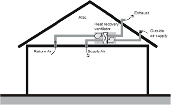
Section 150.0(m)12 requires that outside air be filtered using MERV 13 (or greater) air filters. The filters must be accessible to facilitate replacement. An example of a heat recovery ventilator is shown in Figure 4-31.
The outdoor air inlet should be located to avoid areas with contaminants such as smoke produced in barbeque areas and products of combustion emitted from gas appliance vents. Air may not be drawn from attics or crawlspaces.
Figure 4-31: Balanced Ventilation Example 1 – HRV or ERV

Source: California Energy Commission
Another balanced system configuration uses a stand-alone supply fan coupled with a stand-alone exhaust fan, both wired to a common switch or control to ensure they operate simultaneously. The controls must make it possible to adjust the speed of the fans for balancing the airflows within 20 percent. An example is shown in Figure 4-32.
Figure 4-32: Balanced Ventilation Example 2 – Separate Supply and Exhaust Fan

Residential Appendix RA3.7.4 provides direction for field measurement of supply, exhaust, and balanced ventilation system types. These measurement procedures are applicable for ventilation systems that operate at a specific airflow rate or systems that operate intermittently at a fixed speed (averaged over any three-hour period), according to a control with a fixed schedule that is verifiable by a HERS rater on site. (Refer to ASHRAE 62.2 Section 4.5.1 Short Term Average Ventilation.)
Variable or intermittent operation that complies with ASHRAE 62.2 Sections 4.5.2 and 4.5.3 complies with the dwelling unit mechanical ventilation requirements by use of varying ventilation airflow rates based on complicated calculations for relative exposure as specified in ASHRAE 62.2 Normative Appendix C. These calculation procedures provide the basis for "smart" ventilation controls implemented by use of digital controls that rely on the manufacturer's product-specific algorithms or software. Any ventilation system models that use these complex ventilation system controls in a ventilation product designed to be used to comply with Standards Section 150.0(o) must submit an application to the Energy Commission to have the ventilation technology approved. These manufacturers are expected to provide with their applications evidence that the system will perform to provide the required dwelling unit mechanical ventilation. The manufacturers are also expected to provide a method that could be used by a HERS Rater to verify that an installed system is operating as designed.
Listings of systems approved by the Energy Commission are located at the following URL: https://www.energy.ca.gov/rules-and-regulations/building-energy-efficiency/manufacturer-certification-building-equipment
Dwelling unit ventilation systems may operate continuously or intermittently. If fan operation is not continuous, the average ventilation rate over any three-hour period must be greater than or equal to the Qfan value calculated using equations in this section.
ASHRAE 62.2 allows for scheduled ventilation and real-time control, but these control approaches require “equivalent exposure” calculations using methods in Normative Appendix C, and complex controls would be required to operate the fan.
Equations for calculating Qfan (the required mechanical ventilation rate) for single-family houses and townhouses are listed below. Single-family detached dwelling units and attached dwelling units not sharing ceilings or floors with other dwelling units, occupiable spaces, public garages, or commercial spaces (e.g. duplexes and townhomes) can take credit for building infiltration using the calculations below.
For ventilation airflow calculations, building infiltration rate (Qinf) varies by climate zone (Table 4-14) and building height. Therefore, the value for Qfan for a single-family dwelling or townhome may also vary based on climate zone and building height.
When the performance compliance approach is used, the compliance software completes all the calculations given in Equations 4-1, 4-2, 4-3, and 4-4, and Qfan is reported on the CF1R. If the prescriptive compliance approach is used, the Data Registry performs the calculations and the value for Qfan is recorded on the CF1R.
The total ventilation rate is the combined volume of ventilation air provided by infiltration and the mechanical ventilation provided from fans, as follows:
Equation 4-1

Where:


For single-family homes, when determining the required dwelling unit mechanical ventilation airflow rate (Qfan in Equation 4-4), the calculated value for estimated infiltration rate (Qinf in Equation 4-2) is deducted from the value of Qtot (determined by Equation 4-1). The calculated value for estimated infiltration rate depends on the building leakage, building height, and the weather and shielding factor, which varies by climate zone (Table 4-14). A default envelope leakage value of 2 ACH50 is mandatory for the fan sizing calculations unless a blower door measurement is performed that determines a leakage rate below 2 ACH50. Leakage in ACH50 must be converted to CFM50 for use in subsequent calculations. Conversion of 2 ACH50 is shown in Equation 4-2.
Equation 4-2
Q50 = Vdu x 2 ACH50)/ 60
Where:
Q50 = leakage rate at 50 Pa, CFM
Vdu = dwelling unit conditioned volume, ft3
ACH50 = air changes per hour at 50 Pa (0.2 inch water)
Vdu can be approximated by multiplying the average ceiling height by the dwelling conditioned floor area. If the field-verified value for ACH50 is less than 2, then the verified value is used in Equation 4-2 instead of 2.
The effective annual infiltration rate (Qinf) is calculated using the weather/shielding factor (wsf) for the applicable climate zone and the building height. See Table 4-14 below and Energy Code Table 150.0-D for values for wsf.
Equation 4-3
 = 0.052 x
Q50 x wsf x [H/Hr]z (CFM)
= 0.052 x
Q50 x wsf x [H/Hr]z (CFM)
Where:
Qinf = effective annual infiltration rate, CFM
Q50 = leakage rate at 50 Pa, CFM

H = vertical distance between the lowest and highest above-grade points within the pressure boundary
Hr = reference height = 8.2 ft
z = 0.4, for the purpose of calculating Qinf
The number of stories multiplied by the average ceiling height (as entered in compliance software) provides sufficient accuracy for determining H.
Table 4-13: Weather and Shielding Factors by Climate Zone
|
CZ |
WSF |
CZ |
WSF |
|
1 |
0.56 |
9 |
0.39 |
|
2 |
0.49 |
10 |
0.42 |
|
3 |
0.54 |
11 |
0.50 |
|
4 |
0.48 |
12 |
0.51 |
|
5 |
0.52 |
13 |
0.45 |
|
6 |
0.45 |
14 |
0.58 |
|
7 |
0.40 |
15 |
0.45 |
|
8 |
0.36 |
16 |
0.44 |
Source: Energy Code Table 150.0-D
The required mechanical ventilation rate, Qfan is the total outside airflow required to be supplied to (or total indoor air required to be exhausted from) the building by fans. For balanced ventilation system, the average of the supply and exhaust airflows must be greater than or equal to Qfan.
Qfan is calculated using Equation 4-4 below, which uses the values for Qtot and Qinf determined above. Equation 4-4 accounts for reduced exterior wall leakage area in attached units (e.g., townhomes and duplexes). Equation 4-4 also accounts for the differences in ventilation effectiveness of balanced systems compared to exhaust/supply (unbalanced) systems due to varying dwelling infiltration leakage rates. If Qfan is less than 10 CFM, then no fan is required.
Equation 4-4
Qfan = Qtot - Φ ( Qinf x Aext)
Where:

 infiltration rate (CFM)
Φ = 1 for balanced ventilation systems or Qinf/Qtot for other system types
Aext = 1 for single-family detached homes. For attached dwelling units not sharing ceilings or floors with other dwelling units, occupiable spaces, public garages, or commercial spaces (e.g., duplexes and townhomes), Aext is the ratio of exterior envelope surface area that is not attached to garages or other dwelling units to total envelope surface area.
Example 4-11 – Required Ventilation
Question:
What is the required continuous ventilation rate for a three-bedroom, 1,800 ft² 2-story townhouse located in Climate Zone 8 that has 9-foot ceilings, and where 25% of the exterior wall surface area adjoins another unit? Ventilation is provided by a bathroom exhaust fan. No extraordinary measures have been taken to seal the building.
Answer:
Equation 4-1 yields a total ventilation rate of 84 CFM
 CFM
CFM
The volume is 1,800 x 9 = 16,200 ft3. Solving for Equation 4-2 results in a leakage rate of 540 CFM
Q50 = Vdu x 2 ACH50/ 60 = 16,200 x 2/60 = 540 CFM
Using
Equation 4-3:  = 0.052 x Q50 x wsf x
[H/Hr]z = 0.052 x 540 x 0.36 x (18/8.2)0.4
= 14 CFM
= 0.052 x Q50 x wsf x
[H/Hr]z = 0.052 x 540 x 0.36 x (18/8.2)0.4
= 14 CFM
And applying Equation 4-4, the mechanical ventilatioen system must move 82 CFM.
Qfan = Qtot – (Qinf/Qtot)(Qinf x Aext) = 84 – (14/84)(14 x (1-0.25)) = 82 CFM
Due to the reduction in infiltration resulting from reduced exterior wall area and to the use of an exhaust fan instead of a balanced system, the effective infiltration credit is only 2 CFM.
Example 4-12
Question:
The two-story house I am building in Climate Zone 12 has a floor area of 2,240 ft² and four bedrooms. I am using an HRV that delivers 80 CFM of outdoor air and exhausts 90 cfm of indoor air. My calculations come out to 86 CFM. Can I use this system?
Answer:
No. For balanced systems, the supply and exhaust airflows can be averaged, and in this case, they average 85 CFM, which is slightly less than the required 86 CFM.
The nominal rating of a fan can be different than what it actually delivers when installed and connected to ductwork, so designers should always include a safety margin when sizing equipment. The length and size of ducting should be used to calculate the pressure drop. This is why dwelling unit ventilation rates must be verified by a HERS Rater.
Example 4-13
Question:
A 2,300 ft² house has exhaust fans running continuously in two bathrooms, providing a total exhaust flow rate of 90 CFM, but the requirement is 98 CFM. What are the options for providing the additional 8 CFM?
Answer:
Option 1: The required additional CFM could be provided either by increasing the size of either or both exhaust fans such that the combined airflow exceeds 98 CFM.
Option 2: Another solution would be to use a balanced system, which may reduce the airflow requirement to below 90 CFM. Adding another 8 CFM fan is not an acceptable solution.
Example 4-14
Question:
A CFI system is connected to the return air plenum of a furnace such that when operating, 10% of the air supplied by the furnace is outdoor air. The CFI control limits furnace fan operation to 30 minutes of every hour. If the house requires 100 CFM of continuous ventilation air, what volume of air must the furnace deliver?
Answer:
Since the furnace operates half the time, the volume of outside air delivered when it is operating must be 2 x 100 = 200 CFM. Therefore, the furnace must be able to deliver 200/0.1 = 2,000 CFM.
Example 4-15
Question:
Can an exhaust fan be used to supplement ventilation air provided by a CFS system?
Answer:
Yes. In the example above, if an exhaust fan is operated continuously to deliver 50 CFM, then the volume of air required of the CFI system is reduced to 100 CFM, or an average of 50 CFM over the hour such that the sum of ventilation air delivered averages 100 CFM. A 1,000 CFM furnace providing 10% outside air could be used in this case. Even though such a combined ventilation system is partially balanced, it would not qualify as a balanced system in the calculation of Qfan.
Example 4-16
Question:
I want to provide controls that disable the ventilation system so it does not bring in outside air during the hottest two hours of the day, and the calculations show I need 80 CFM continuous. How large must my fan be?
Answer:
If the average rate over three hours is 80 CFM and the fan only operates one hour, then it must be capable of delivering 3 x 80 = 240 CFM. ASHRAE 62.2 does not allow averaging ventilation over more than a three-hour period.
From ASHRAE 62.2, Section 4.4, Control and Operation. A readily accessible manual ON-OFF control, including but not limited to a fan switch or a dedicated branch-circuit overcurrent device, shall be provided. Controls shall include text or an icon indicating the system’s function.
Exception: For multifamily dwelling units, the manual ON-OFF control shall not be required to be readily accessible.
From Energy Code Section 150.0(o)1J: Compliance with ASHRAE 62.2 Section 4.4 (Control and Operation) shall require manual ON-OFF control switches associated with whole-dwelling unit ventilation systems to have a label clearly displaying the following text, or equivalent text: "This switch controls the indoor air quality ventilation for the home. Leave switch in the “on” position at all times unless the outdoor air quality is very poor."
ASHRAE 62.2 requires that the ventilation system have an override control that is accessible to the occupants. The control must be capable of being accessed quickly and easily by the occupants. It can be a labeled wall switch or a circuit breaker located in the electrical panel, or it may be integrated into a labeled wall-mounted control. It cannot be buried in the insulation in the attic or inside the installed ventilation fan cabinet. The occupant must have easy access to modify the fan control settings or turn off the system, if necessary.
Bathroom exhaust fans may serve a dual purpose to provide whole-dwelling unit ventilation when operating at a low constant airflow rate and to provide local demand controlled ventilation by operating at a higher "boost" airflow rate, when needed. For these system types, the continuous whole-dwelling unit airflow operation must have an ON/OFF override, which may be located in the bathroom or in a remote accessible location. The "boost" function is controlled by a separate wall switch located in the bathroom or by a motion sensor or humidistat located in the bathroom.
Time-of-day timers or duty-cycle timers can be used to control intermittent dwelling unit ventilation. Manual crank timers cannot be used since the system must operate automatically without intervention by the occupant. Some controls “look back” over a set time interval to see if the CFI system air handler has already operated for heating or cooling before it turns on the air handler for ventilation-only operation.
See Section 4.6.4 for additional information about Energy Commission approval of ventilation controls.
Example 4-17 – Control Options
Question:
A bathroom exhaust fan is used to provide dwelling unit ventilation for a house. The fan is designed to be operated by a typical wall switch. Is a label on the wall plate necessary to comply with the requirement that controls be “appropriately labeled”?
Answer:
Yes. Since the fan is providing the required dwelling unit ventilation, a label is needed to inform the occupant that this switch controls the indoor air quality ventilation for the home and directs the occupant to leave it on unless the outdoor air quality is very poor. If the exhaust fan were serving only the local exhaust requirement for the bathroom, then a label would not be required.
Example 4-18 – Thermostatic Control
Question:
Ventilation air is provided whenever the air handler operates via a duct run connecting the return side of the central air handler to the outdoors. The system is estimated to run on calls for heating and cooling about 40 percent of the time, averaged over the year. If it is assumed that the air handler runs only 25 percent of the time, and the airflow is sized accordingly, can the system be allowed to run under thermostatic control?
Answer:
No. A system under thermostatic control will go through periods with little or no operation when the outdoor temperature is near the indoor set point, or if the system is in setback mode. An intermittently operating ventilation system must be controlled by a timer that will cycle at least once every three hours to assure that adequate ventilation is provided regardless of outdoor conditions. Alternatively, a more complex control may be used if it complies with the requirements in ASHRAE 62.2 Appendix C. These systems must be approved by the Energy Commission before being allowed for use for compliance with the required dwelling unit ventilation.
Cycle timer controls are available that keep track of when (and for how long) the system operates to satisfy heating/cooling requirements in the home. These controls turn on the central fan to provide additional ventilation air when heating/cooling operation of the central fan has not already operated for a long enough period to provide the required ventilation. When choosing cycle timer controls for compliance, it is necessary to use models that have been approved by the Energy Commission for use for compliance with dwelling unit mechanical ventilation.
For builders using the performance compliance approach, the energy use of whole-dwelling unit ventilation fans is factored into the compliance of the proposed building. Proposed designs with lower fan efficacy, higher W/CFM, than the standard design will get a compliance penalty and proposed designs with higher fan efficacy will get a compliance credit. Whole-dwelling unit ventilation airflow rate is also a factor in the performance approach. Proposed designs exceeding the standard design ventilation airflow rate, higher CFM than the standard, will see a compliance penalty due to the additional fan energy. In most cases the standard design will match the proposed design ventilation rate and compliance will be neutral for airflow rate. However, the standard design will only match the proposed design airflow rate up to a limit and additional airflow will count against the proposed design energy budget. More information on the standard design ventilation fan efficacy and airflow rate limit can be found in the Residential ACM Reference Manual. For balanced heat recovery or energy recovery ventilators (H/ERVs), the HVI rated heat recovery efficiency can help offset higher fan energy use for balanced ventilation systems.
The fan efficacy of the central air handler used for a CFI ventilation system must conform to the same fan watt draw (W/CFM) limit as for cooling systems in all climate zones as verified by a HERS Rater in accordance with the diagnostic test protocols given in RA3.3. The RA3.3 verification of CFI systems determines the W/CFM of the total central system airflow, not the W/CFM of the ventilation airflow.
The Energy Code does not regulate the energy use of ventilation fans installed for other purposes, such as local exhaust.
§150.1(f)10
CFI system automatic controls must operate the central system air handler fan (generally part of every hour of the year) to draw in and distribute ventilation air throughout the dwelling, even when there is no heating or cooling required. The Energy Code prohibits CFI systems from operating continuously. Because the CFI ventilation control increases the central system air handler fan run time significantly, and because typical central system air handler fan and duct systems require a large amount of power, a CFI ventilation system can use a large amount of electricity annually.
The fan efficacy of CFI systems must be verified using the same methods as required for furnaces and air handlers. (See RA3.3.) The central system air handler must be operating in ventilation mode with the outdoor air damper open and with ventilation air flowing into the return plenum from outside the building. Furthermore, the airflow that must be measured is the total airflow through the air handler (system airflow), which is the sum of the return airflow, and the outside air ducted to the return plenum (ventilation airflow). To pass the test, the watt draw must be less than or equal to 0.45 W/CFM for furnaces, and 0.58 W/CFM for air handlers that are not gas furnaces, or 0.62 W/CFM for small duct high velocity systems.
Using the prescriptive or performance approach, the maximum mandatory fan efficacy for HRV/ERVs is 1.0 W/CFM. This must be HERS verified in accordance with RA3.7.4.4. For balanced systems without heat recovery, exhaust, or supply ventilation fans there are no mandatory or prescriptive fan efficacy requirements.
When using the performance approach, the airflow rate and fan watt draw of the fan must be entered into the compliance software. Values for airflow and fan W/CFM information may be available from the HVI directory at https://www.hvi.org/proddirectory/CPD_Reports/section_1/index.cfm. If HVI does not list fan energy for the installed model, use information from the manufacturer's published documentation. When fan energy is listed as CFM/W instead of W/CFM, it is necessary to invert the value to provide W/CFM as input to the compliance software (for example: 4 CFM/ W = 1/4 W/CFM = 0.25 W/CFM).
Dwelling unit ventilation is not compliance neutral and performance compliance will be affected by the proposed design W/CFM, ventilation airflow rate, and heat recovery if present. Installation of designs exceeding the standard design W/CFM or ventilation rate will get a compliance penalty. More information on the standard design ventilation fan W/CFM and airflow rate can be found in the Residential ACM Reference Manual.
If an H/ERV is specified, the heat recovery efficiency of the proposed system must be entered into the compliance software so that the heat recovery effect can be accounted for in the compliance simulation. Many factors affect the benefit of heat recovery on ventilation, like climate zone and building design, but in general heat recovery will increase building compliance.
Local exhaust (sometimes called spot ventilation) has long been required for bathrooms and kitchens to remove moisture and odors at the source. Building codes have required an operable window or an exhaust fan in bathrooms for many years and have generally required kitchen exhaust either directly through a fan or indirectly through a recirculating range hood and an operable window. The Energy Code recognizes the limitations of these indirect methods of reducing moisture and odors and requires that these spaces be mechanically exhausted directly to outdoors, even if windows are present. Moisture condensation on indoor surfaces is a leading cause of mold and mildew in buildings. The occurrence of asthma is also associated with high interior relative humidity. Therefore, it is important to exhaust the excess moisture from bathing and cooking directly at the source.
The Energy Code requires that each kitchen and bathroom have a local mechanical exhaust system. Generally, this will be a dedicated exhaust fan in each room that requires local exhaust, although ventilation systems that exhaust air from multiple rooms using a duct system connected to a single exhaust fan are allowed as long as the minimum local exhaust requirement is met in all rooms served by the system.
The Energy Code follows the ASHRAE 62.2 definitions for kitchens and bathrooms for these ventilation requirements. Kitchens are any rooms containing cooking appliances, and bathrooms are any rooms containing a bathtub, shower, spa, or other similar source of moisture. A room containing only a toilet is not required to have an exhaust fan; ASHRAE 62.2 assumes there is an adjacent bathroom with local exhaust.
Non-enclosed kitchens are required to have demand-controlled local exhaust (as described in Section 4.6.7.1). Enclosed kitchens and bathrooms can have either demand-controlled local exhaust or continuous local exhaust (as described in Section 4.6.7.2). Local exhaust systems must be rated for airflow in accordance with ASHRAE 62.2 section 7.1.
Building codes may require that fans used for kitchen range hood exhaust ventilation be safety-rated by UL or some other testing agency for the particular location and/or application. Typically, these requirements address fire safety issues of fans placed within an area defined by a set of lines at 45° outward and upward from the cooktop. Few bathroom exhaust fans will have this rating, so they cannot be used in these locations.
Example 4-19 – Local Exhaust Required for Toilet
Question:
I am building a house with 2½ baths. The half-bath consists of a room with a toilet and sink. Is local exhaust required for the half bath?
Answer:
No. Local exhaust is required only for bathrooms, which are defined in the Energy Code as rooms with a bathtub, shower, spa or some other similar source of moisture. This does not include a simple sink for occasional hand washing.
Example 4-20
Question:
The master bath suite in a house has a bathroom with a shower, spa, and sinks. The toilet is in a separate, adjacent room with a full door. Where do I need to install local exhaust fans?
Answer:
The standards require local exhaust only in the bathroom, not the separate toilet room.
The Energy Code requires that local exhaust fans be designed to be operated by the occupant. This usually means that a wall switch or some other control is accessible and obvious. There is no requirement to specify where the control or switch needs to be located, but bathroom exhaust fan controls are generally located next to the light switch, and kitchen exhaust fan controls are generally integrated into the range hood or mounted on the wall or counter adjacent to the range hood.
Bathrooms can use a variety of exhaust strategies. They can use ceiling-mounted exhaust fans or may use a remotely mounted fan ducted to two or more exhaust grilles. Demand-controlled local exhaust can be integrated with the dwelling unit ventilation system to provide both functions. Kitchens can have range hood exhaust fans, down-draft exhausts, ceiling- or wall-mounted exhaust fans, or pickups for remote-mounted inline exhaust fans. Generally, HRV/ERV manufacturers do not allow exhaust ducting from the kitchen because of the heat, moisture, grease, and particulates that should not enter the heat exchange core. Building codes require kitchen exhaust fans to be connected to metal ductwork for fire safety.
Example 4-21 – Ducting Kitchen Exhaust to the Outdoors
Question:
How do I know what kind of duct I need to use? I’ve been using recirculating hoods my entire career, now I need to vent to the outdoors. How do I do it?
Answer:
A kitchen range hood or downdraft duct is generally a smooth metal duct that is sized to match the outlet of the ventilation device. It is often a six-inch or seven-inch-round duct, or the range hood may have a rectangular discharge. If it is rectangular, the fan will typically have a rectangular-to-round adapter included. Always use a terminal device on the roof or wall that is sized to be at least as large as the duct. Try to minimize the number of elbows used.
Example 4-22
Question:
How do I know what the requirements are in my area?
Answer:
Ask your code enforcement agency for that information. Some enforcement agencies will accept metal flex; some will not.
A. Control and Operation for Intermittent Local Exhaust
The choice of control is left to the designer. It can be a manual switch or automatic control like an occupancy sensor. Some exhaust fans have multiple speeds, and some fan controls have a delay-off function that operates the exhaust fan for a set time after the occupant leaves the bathroom. New control strategies continue to come to the market. The only requirement is that there is a control. Title 24, Part 11 may specify additional requirements for the control and operation of intermittent local exhaust.
B. Ventilation Rate for Demand-Controlled Local Exhaust
Cooking is a regularly occurring activity inside a home that causes indoor pollution. The most effective method in removing pollutants generated from cooking is to use a vented kitchen range hood, which removes pollutants above the cooking surface before they mix with the air in the rest of the home. The 2022 Energy Code incorporates a new metric for local exhaust called capture efficiency. Capture efficiency is defined as the fraction of emitted tracer gas that is directly exhausted by a range hood.
To adequately capture the moisture, particulates, and other products of cooking and/or combustion in kitchens, the Energy Code requires minimum ventilation rates or capture efficiencies in Table 4-15 and Table 4-16. Only in kitchens that are enclosed, the exhaust requirement can also be met with either a ceiling or wall-mounted exhaust fan or with a ducted fan or ducted ventilation system that can provide at least five air changes of the kitchen volume per hour. Recirculating range hoods that do not exhaust pollutants to the outside cannot be used to meet the requirements of ASHRAE Standard 62.2.
Table 4-14: Kitchen Range Hood Airflow Rates and Capture Efficiency Ratings (from Table 150.0G)
|
Dwelling Unit Floor Area (ft2) |
Hood Over Electric Range |
Hood Over Gas Range |
|
>1500 |
50% CE or 110 cfm |
70% CE or 180 cfm |
|
>1000 - 1500 |
50% CE or 110 cfm |
80% CE or 250 cfm |
|
750 - 1000 |
55% CE or 130 cfm |
85% CE or 280 cfm |
|
<750 |
65% CE or 160 cfm |
85% CE or 280 cfm |
Table 4-15: Demand-Controlled Local Ventilation Exhaust Airflow Rates (from Table 150.0-E)
|
Application |
Airflow |
|
Enclosed Kitchen |
Vented range hood (including appliance-range hood combinations): capture efficiency or airflow rate specified in Table 4-14. Other kitchen exhaust fans, including downdraft: 300 CFM (150 L/s) or a capacity of 5 ACH |
|
Non-Enclosed Kitchen |
Vented range hood (including appliance-range hood combinations): capture efficiency or airflow rate specified in Table 4-14. Other kitchen exhaust fans, including downdraft: 300 CFM (150 L/s) |
|
Bathroom |
50 CFM (25 L/s) |
The Energy Code requires verification that range hoods are HVI or AHAM-certified to provide at least one speed setting at which they can deliver at least 100 CFM at a noise level of 3 sones or less. Verification must be in accordance with the procedures in RA3.7.4.3. Range hoods that have a minimum airflow setting exceeding 400 CFM are exempt from the noise requirement.
Ratings for Local Exhaust Fans are listed at the following web pages:
•Home Ventilating Institute (HVI) at https://www.hvi.org/proddirectory/CPD_Reports/section_1/index.cfm
•Association of Home Appliance Manufacturers (AHAM) at https://www.aham.org/AHAM/What_We_Do/Kitchen_Range_Hood_Certification
ASHRAE Standard 62.2 limits exhaust airflow when atmospherically vented combustion appliances are located inside the pressure boundary. This is particularly important to observe when large range hoods are installed. Refer to Section 4.6.9.4 below for more information.
Example 4-23 – Ceiling or Wall Exhaust vs Demand-Controlled Range Hood in an Enclosed Kitchen
Question:
I am building a house with an enclosed kitchen that is 12 ft. x 14 ft. with a 10 ft. ceiling. What size ceiling exhaust fan or range hood fan is required?
Answer:
If a range hood exhaust is not used, either 300 CFM or 5 ACH minimum airflow is required. The kitchen volume is 12 ft. x 14 ft. x 10 ft. = 1,680 ft3. Five air changes are a flow rate of 1,680 ft³ x 5/ hr. ÷ 60 min/hr = 140 CFM. So, this kitchen must have a ceiling or wall exhaust fan of 140 CFM. Otherwise, a vented range hood fan that provides at least 100 CFM is required.
The Energy Code allows the designer to install a local exhaust system that operates without occupant intervention continuously and automatically during all occupiable hours. Continuous local exhaust is generally specified when the local exhaust ventilation system is combined with a continuous dwelling unit ventilation system. For example, if the dwelling unit ventilation is provided by a continuously operating exhaust fan located in the bathroom, this fan may also satisfy the local exhaust requirement for that bathroom, provided the fan provides airflow greater than or equal to the minimum continuous local ventilation airflow rate. Continuous local exhaust may also be part of a pickup, or an interior grille, for a remote fan or HRV/ERV system.
Continuously operating bathroom exhaust fans must operate at a minimum of 20 CFM. Continuously operating kitchen exhaust fans are permitted only for enclosed kitchens.
Table 4-17: Continuous Local Ventilation Exhaust Airflow Rates (from Table 150.0-F)
Example 4-24 – Continuous Kitchen Exhaust
Question:
A new house has an open-design, 12 ft. x18 ft. ranch kitchen with 12 ft. cathedral ceilings. What airflow rate will be required for a continuous exhaust fan?
Answer:
A continuous exhaust fan cannot be used in non-enclosed kitchens. A vented range hood must be provided.
From ASHRAE 62.2,
6.1 Adjacent Spaces and Transfer Air. Measures shall be taken to minimize air movement across envelope components to dwelling units from adjacent spaces such as garages, unconditioned crawlspaces, unconditioned attics, and other dwelling units. Pressure boundary wall, ceiling, and floor penetrations shall be sealed, as shall any vertical chases adjacent to dwelling units. Doors between dwelling units and common hallways shall be gasketed or made substantially airtight.
Supply and balanced ventilation systems shall be designed and constructed to provide ventilation air directly from the outdoors.
ASHRAE Standard 62.2 requires that the air used for ventilation come from outdoors. Air may not be drawn in as transfer air from other spaces that are outside the occupiable space of the dwelling unit, or from between dwelling units and corridors. This is to prevent airborne pollutants originating in those other spaces from contaminating the dwelling unit. For example, drawing ventilation air from the garage could introduce VOCs or pesticides into the indoor air. Drawing ventilation air from an unconditioned crawlspace could cause elevated allergen concentrations in the dwelling such as mold spores, insects, or rodent allergens. Likewise, drawing air from an adjacent dwelling could introduce unwanted contaminants such as cooking odors or cigarette smoke.
In addition to designing the ventilation system to introduce outdoor air, ASHRAE 62.2 also requires that measures be taken to prevent air movement between adjacent spaces, such as attics, garages, crawlspaces, and utility chases. This includes thorough air sealing of envelope components, pressure management and use of airtight recessed ceiling light fixtures. The measures must apply to adjacent units above and below, as well as side by side.
Air sealing must include pathways in vertical components such as demising walls and walls common to the unit and an attached garage, and in horizontal components such as floors and ceilings. Pipe and electrical penetrations are examples of leakage areas that require sealing.
From ASHRAE 62.2, Section 6.2, Instructions and Labeling.
Information on the ventilation design and/or ventilation systems installed, instructions on their proper operation to meet the requirements of this standard, and instructions detailing any required maintenance (similar to that provided for HVAC systems) shall be provided to the owner and the occupant of the dwelling unit. Controls shall be labeled as to their function (unless that function is obvious, such as toilet exhaust fan switches).
From Energy Code Section 150.0(o)1J:
Compliance with ASHRAE 62.2 Section 4.4 (Control and Operation) shall require manual ON-OFF control switches associated with whole-dwelling unit ventilation systems to have a label clearly displaying the following text, or equivalent text: "This switch controls the indoor air quality ventilation for the home. Leave switch in the “on” position at all times unless the outdoor air quality is very poor.
Field studies have shown that switches for exhaust fans do not have the required labels, and that many homeowners do not understand the importance of continuous operation of the ventilation fans for maintaining indoor air quality. Standards Section 10-103(b)4 require the builder to leave in the building, for the building owner at occupancy, a description of the quantities of outdoor air that the ventilation system(s) are designed to provide to the conditioned space of the building and instructions for proper operation and maintenance of the ventilation system.
Because the concept of a designed dwelling unit ventilation system may be new to many occupants, the standards section requires that ventilation system controls be labeled as to function. One acceptable option is to affix a label to the electrical panel that provides some basic system operation information.
From ASHRAE 62.2, Section 6.3, Clothes Dryers.
Clothes dryers shall be exhausted directly to the outdoors. Exception: Condensing dryers plumbed to a drain.
All laundry rooms must be built with a duct to the outdoors, designed to be connected to the dryer. Devices that allow the exhaust air to be diverted into the indoor space to provide extra heating are not permitted. This requirement is consistent with existing clothes dryer installation and design standards.
Example 4-25 – Clothes Dryer Exhaust Diverter
Question:
I am building a home that has been purchased prior to completion. The buyer has asked for an exhaust air diverter to be installed in the dryer exhaust duct. He says that it is wasteful of heating energy to exhaust the warm humid air to the outdoors during the winter when the furnace and humidifier are working. He says that the screen on the diverter will prevent excess dust being released into the space. Can I install the device for him?
Answer:
No. The feature will not comply with the Energy Code. The device is specifically prohibited. Significant amounts of dust are released from such devices, and the moisture in the dryer exhaust can lead to humidity problems, particularly in warmer climates.
From ASHRAE 62.2, Section 6.4, Combustion and Solid-Fuel Burning Appliances
6.4.1 Combustion and solid-fuel burning appliances must be provided with adequate combustion and ventilation air and installed in accordance with manufacturers’ installation instructions, NFPA 31, NFPA 54/ANSI Z223.1, NFPA 211,or other equivalent code acceptable to the building official.
6.4.2 Where atmospherically vented combustion appliances or solid-fuel burning appliances are located inside the pressure boundary, the total net exhaust flow of the two largest exhaust fans (not including a summer cooling fan intended to be operated only when windows or other air inlets are open) shall not exceed 15 CFM per 100 ft2 (75 L/s per 100 m2) of occupiable space when in operation at full capacity. If the designed total net flow exceeds this limit, the net exhaust flow must be reduced by reducing the exhaust flow or providing compensating outdoor air. Gravity or barometric dampers in nonpowered exhaust makeup air systems shall not be used to provide compensating outdoor air. Atmospherically vented combustion appliances do not include direct-vent appliances. Combustion appliances that pass safety testing performed according to ANSI/BPI-1200, shall be deemed as complying with Section 6.4.2.
ASHRAE Standard 62.2 requires that the vent system for combustion appliances be properly installed, as specified by the instructions from the appliance manufacturer and by the California Building Code. Compliance with venting requirements involves determining the type and size of duct material to be used, and routing requirements for the exhaust ducting system.
ASHRAE Standard 62.2 includes a provision intended to prevent back drafting, where one or more exhaust fans are installed in a home with atmospherically vented or solid fuel combustion appliances. If the two largest exhaust fans have a combined capacity that exceeds 15 CFM/100 ft² of floor area, then makeup air must be provided. This provision applies only when the atmospherically vented appliance is inside the pressure boundary and the house does not include a summer cooling fan that is designed to be operated only when windows are open. Direct-vent appliances are not considered “atmospherically vented.”
The two largest exhaust fans are normally the kitchen range hood and the clothes dryer (if located inside the dwelling unit pressure boundary). Large-range hoods, particularly downdraft range hoods, can have capacities of 1,000 CFM or more.
Issues relating to this can be solved in several ways. First, all atmospherically vented combustion appliances can be located outside the pressure boundary of the house (to the garage or outdoor utility closet). Second, the flow rate of one or more of the fans can be reduced so the combined exhaust flow is less than 15 CFM/100 ft² floor area Finally, outdoor makeup air can be mechanically provided to reduce the net exhaust rate.
In addition to meeting ASHRAE 62.2, Section 6.4, all dwelling units must also conform to the applicable requirements specified in the California Mechanical Code Chapter 7 for combustion air.
Example 4-26 – Large Exhaust Fan
Question:
I am building a 3,600 ft2 custom home that has four bedrooms. The kitchen will have a high-end range hood that has three speeds, nominally 1,000 CFM, 1,400 CFM and 1,600 CFM. The house will include an atmospherically vented gas water heater located in the basement. If I am using a central exhaust fan for the dwelling unit ventilation of 75 CFM, and there is a clothes dryer installed, how much compensating outdoor airflow (makeup air) is needed?
Answer:
You must use the high-speed value for the range hood of 1,600 CFM. The clothes dryer flow is assumed to be 150 CFM for sizing purposes. These two flows are added together for a total exhaust capacity of 1,750 CFM. Since the whole-dwelling unit ventilation fan is not one of the two largest exhaust fans, it does not figure into the makeup air calculation. Using the equation above, at least 1,750 CFM – (15 CFM x 3,600 ft² / 100 ft²) = 1,210 CFM of makeup outside airflow must be provided
Example 4-27
Question:
The same custom house will have the water heater located in the garage instead of the basement. Does that change anything?
Answer:
Garages (and attics) are normally located outside the pressure boundary, so makeup air is not required. If the garage is inside the pressure boundary of the living space, makeup air is required.
Example 4-28
Question:
For this house, I need to keep the natural gas water heater in the basement. What are my options that would avoid the requirement to provide makeup air?
Answer:
There are several things you could do. First, you could use a direct vent water heater that would also provide higher fuel efficiency. You could use a lower capacity range hood, one that is less than 390 CFM (15 CFM x 3,600 ft² / 100 ft² – 150 CFM). Use of continuous supply-only dwelling unit ventilation would allow the hood capacity to increase to 465 CFM (15 CFM x 3,600 ft² / 100 ft² – 150 CFM + 75 CFM). There are also commercial range hoods available that are designed to provide makeup air.
From ASHRAE 62.2, Section 6.5.1, Garages.
When an occupiable space adjoins a garage, the design must prevent migration of contaminants to the adjoining occupiable space. Air seal the walls, ceilings, and floors that separate garages from occupiable space. To be considered air-sealed, all joints, seams, penetrations, openings between door assemblies and their respective jambs and framing, and other sources of air leakage through wall and ceiling assemblies separating the garage from the residence and its attic area shall be caulked, gasketed, weather stripped, wrapped, or otherwise sealed to limit air movement. Doors between garages and occupiable spaces shall be gasketed or made substantially airtight with weather stripping.
Garages often contain numerous sources of air contaminants, including. vehicle exhaust, gasoline fumes, pesticides, paints and solvents. When a garage is attached to the house, these contaminants be prevented from entering the living space. Walls between the home and garage (or garage ceiling in designs with living space above garages) shall be designed and constructed to prevent air flow through the wall or ceiling. Common doors and any air handlers or ducts located in the garage shall also be sealed, weather-stripped, or gasketed.
Energy Code Section 150.0(o) specifies that compliance with ASHRAE 62.2 Section 6.5.2 (Space Conditioning System Ducts) shall not be required. However, applicable duct leakage verification requirements are given in Energy Code Sections §150.0(m)11 for newly constructed buildings, and 150.2(b)iD for alterations to systems in existing buildings. All ducted space conditioning systems in newly constructed buildings are required to pass HERS verification that the duct system leaks less than or equal to 5 percent of the system airflow rate. This requirement also applies to portions of the system that may be in a garage space.
For alterations to space conditioning systems in existing buildings that have all or portions of the forced air ducts, plenums or air-handling units in the garage, Section 150.2(b)1D specifies two compliance approaches:
1. The measured system duct leakage shall be less than or equal to 6 percent of system air handler airflow as determined using the procedures in RA3.1.4.3.1.
2. All accessible leaks located in the garage space shall be sealed and verified through a visual inspection and a smoke test by a certified HERS Rater using the methods specified in RA3.1.4.3.5.
For additions and alterations to existing buildings, any length of new or altered duct located in the garage or any new or altered air-handling unit located in the garage triggers these duct leakage testing requirements.
Example 4-29 – Garages
Question:
In a newly constructed building, the building designer located the air handler in the garage. The main return trunk from the dwelling is connected to the air handler. Is this acceptable?
Answer:
Yes. The duct system must be leak-tested and verified to leak no more than 5 percent of air handler airflow.
Example 4-30
Question:
For an alteration to an existing building, the air handler is located in the dwelling unit, and a portion of the return duct is run through the garage to a bedroom above the garage. The return duct has 4 feet of length located in the garage, and this 4-foot section is being replaced. How do I test that length of the duct for leakage?
Answer:
First, test the leakage for the entire duct system to determine whether the total system duct leakage is no greater than 6 percent of the total fan flow. If the system does not meet the 6 percent target for compliance, then use the visual inspection and smoke test specified in RA3.1.4.3.5 and seal all accessible leaks in the 4-foot section of duct that is in the garage space.
From ASHRAE 62.2, Section 6.6 Ventilation Opening Area
Spaces shall have ventilation openings as listed in the following subsections. Such openings shall meet the requirements of Section 6.8.
Exception: Attached dwelling units and spaces that meet the local ventilation requirements set for bathrooms in Section 5.
6.6.1 Habitable Spaces. Each habitable space shall be provided with ventilation openings with an openable area not less than 4% of the floor area or less than 5 ft2 (0.5 m2).
6.6.2 Toilets and Utility Rooms. Toilets and utility rooms shall be provided with ventilation openings with an openable area not less than 4% of the room floor area or less than 1.5 ft2 (0.15 m2).
Exceptions:
1. Utility rooms with a dryer exhaust duct.
2. Toilet compartments in bathrooms.
The dwelling unit mechanical ventilation rate is intended to provide adequate ventilation to typical new homes under normal circumstances. On occasion, however, houses experience unusual circumstances where high levels of contaminants are released into the space. When this occurs, a means of providing the significantly higher levels of ventilation required to remove the contaminants is needed. Operable windows are the most likely means of providing the additional ventilation.
This section of ASHRAE Standard 62.2 requires ventilation openings in habitable spaces, toilets, and utility rooms. Ventilation openings usually mean operable windows, although a dedicated non-window opening for ventilation is acceptable. Spaces that meet the local exhaust requirements are exempted from this requirement.
Habitable spaces are required to have ventilation openings with an openable area equal to at least 4 percent of conditioned space floor area, but not less than 5 ft2. Dining rooms, living rooms, family rooms, bedrooms, and kitchens are considered habitable space. Closets, crawl spaces, garages, and utility rooms are generally not. If the clothes washer and dryer are located in an open basement that is also the family room, it would be considered habitable space.
The openings do not have to be windows. They can also be operable, insulated, weather-stripped panels.
Ventilation openings, which include operable windows, skylights, through-the-wall vents, window vents, or similar devices, shall be readily accessible to the occupant. This means that the occupant must be able to operate the opening without having to climb on anything. An operable skylight must have some means of being operated while standing on the floor: a push rod, a long crank handle, or an electric motor.
If a ventilation opening is covered with louvers or otherwise obstructed, the openable area is the unobstructed free area through the opening.
Example 4-31 – Ventilation Openings
Question:
I am building a house with a 14 ft. by 12 ft. bedroom. What size window do I need to install?
Answer:
It depends on the type of window. The standard requires that the openable area of the window, not the window unit, be 4 percent of the floor area, or 14 ft x 12 ft x 0.04 = 6.7 ft². The fully opened area of the window or windows must be greater than 6.7 ft2. The requirement for this example can be met using two double-hung windows, each with a fully opened area of 3.35 ft2. Any combination of windows whose opened areas add up to at least 6.7 ft2 will meet the requirement.
Compliance with ASHRAE 62.2 Sections 6.7 (Minimum Filtration) and 6.7.1 (Filter Pressure Drop) are not required (Energy Code Section 150.0(o)1D). However, air filtration for mechanical systems must conform to the specifications in Energy Code Section 150.0(m)12. Information on air filtration requirements is given in Section 4.4.1.14 of this chapter.
From ASHRAE 62.2, Section 6.8, Air Inlets.
Air inlets that are part of the ventilation design shall be located a minimum of 10 ft (3 m) from known sources of contamination such as a stack, vent, exhaust hood, or vehicle exhaust. The intake shall be placed so that entering air is not obstructed by snow, plantings, or other material. Forced air inlets shall be provided with rodent/insect screens (mesh not larger than 1/2 in. [13 mm]).
Exceptions:
1. Ventilation openings in the wall may be as close as a stretched-string distance of 3 ft (1 m) from sources of contamination exiting through the roof or dryer exhausts.
2. No minimum separation distance shall be required between windows and local exhaust outlets in kitchens and bathrooms.
3. Vent terminations covered by and meeting the requirements of the National Fuel Gas Code (NFPA 54/ANSI Z223.1)7 or equivalent.
4. Where a combined exhaust/intake termination is used to separate intake air from exhaust air originating in a living space other than kitchens, no minimum separation distance between these two openings is required. For these combined terminations, the exhaust air concentration within the intake airflow shall not exceed 10%, as established by the manufacturer.
6.8.1 Ventilation Openings.
Operable windows, skylights, through-the-wall inlets, window air inlets, or similar devices shall be readily accessible to occupants. Where openings are covered with louvers or otherwise obstructed, openable area shall be based on the free, unobstructed area through the opening.
When the ventilation system is designed with outdoor air inlets, the inlets must be located away from locations that can be expected to be sources of contamination. The minimum separation is 10 ft. Inlets include not only inlets to ducts, but windows that are needed to achieve the minimal opening area.
For residential buildings, typical sources of outdoor air contaminants include:
1. Vents from combustion appliances
2. Fireplace chimneys.
3. Exhaust fan outlets.
4. Barbeque grills.
5. Driveways or any location where vehicles may be idling.
6. Any other locations where outdoor air contaminants are generated.
The Energy Code also requires that air intakes be placed so that they will not become obstructed by snow, plants, or other material. Forced air inlets must also be equipped with insect/rodent screens with mesh is no larger than 1/2 inch.
From ASHRAE 62.2, Section 7.1, Selection and Installation.
Ventilation devices and equipment serving individual dwelling units shall be tested in accordance with ANSI/ASHRAE Standard 51/AMCA 210 and ANSI/AMCA Standard 300 and rated in accordance with the airflow and sound rating procedures of the Home Ventilating Institute (HVI 915, 916, 920). Installations of systems or equipment shall be carried out in accordance with manufacturers’ design requirements and installation instructions.
Ventilation systems used to meet whole-dwelling unitor local exhaust ventilation requirements shall be rated to deliver the required airflow and have sound ratings that meet the requirements of this section.
ASHRAE Standard 62.2 requires that equipment used to comply with the standard be selected based on tested and certified ratings for airflow and sound. Fan selections must meet the requirements of the standard. The HVI or AHAM certified product directories lists equipment that has been tested for performance and sound at available settings and configurations.
In addition, the Energy Code requires that fans be installed in accordance with the manufacturer’s instructions. Adherence to the installation instructions and other literature shipped with the fan will ensure the installation complies with the ratings.
From ASHRAE 62.2, Section 7.2, Sound Ratings for Fans.
Ventilation fans shall be rated for sound at no less than the minimum airflow rate required by this standard as noted below. These sound ratings shall be at a minimum of 0.1 in. w.c. (25 Pa) static pressure in accordance with the HVI procedures referenced in Section 7.1.
Exception: HVAC air handlers and remote mounted fans need not meet sound requirements. To be considered for this exception, a remote mounted fan must be mounted outside the habitable spaces, bathrooms, toilets, and hallways, and there must be at least 4 ft (1 m) of ductwork between the fan and the intake grille.
7.2.1 Dwelling-Unit Ventilation or Continuous Local Exhaust Fans. These fans shall be rated for sound at a maximum of 1.0 sone.
7.2.2 Demand-Controlled Local Exhaust Fans. Bathroom exhaust fans used to comply with Section 5.2 shall be rated for sound at a maximum of 3 sones. Kitchen exhaust fans used to comply with Section 5.2 shall be rated for sound at a maximum of 3 sones at one or more airflow settings greater than or equal to 100 CFM (47 L/s).
Exception: Fans with a minimum airflow setting exceeding 400 CFM (189 L/s) need not comply.
Energy Code Section 150.0(o)1G requires kitchen range hoods to be rated for sound in accordance with Section 7.2 of ASHRAE 62.2 and provides an exception to allow kitchen range hoods to be rated for sound at a static pressure determined at working speed as specified in HVI 916 Section 7.2. The static pressure at working speed may be lower than 0.1 inch w.c.
One common reason ventilation equipment may not be operated by occupants, particularly local exhaust fans, is the noise the fans may create. To address this, ASHRAE Standard 62.2 requires that certain fans be rated for sound and that installed fans shall have ratings below specified limits. The sound rating must be done at an airflow that is no less than the airflow that the fan must provide to meet the ventilation airflow requirement.
Because of the variables in length and type of duct and grille, there is no standard test method for rating the sound of ventilation fans that are not mounted in the ceiling or wall surface. Consequently, air handlers, HRV/ERVs, inline fans, and remote fans are exempted from the sound rating requirements that apply to surface-mounted fans. However, to reduce the noise conducted from the fan to the grille, the Energy Codes requires at least 4 feet of ductwork between the fan and surface grille. Especially if hard metal duct is used, flexible insulated sound-attenuating duct can be used to reduce the transmitted sound into the space.
A. Continuous Ventilation Fans (Surface-Mounted Fans)
Continuously operated fans shall be rated at 1.0 sone or less. This applies to both whole-dwelling unit and local exhaust ventilation fans.
B. Intermittent or Demand Controlled Fans (Surface-Mounted Fans)
Intermittently operated dwelling unit ventilation fans shall be rated at a maximum of 1.0 sone. Demand-controlled local exhaust fans shall be rated at a maximum of 3.0 sones unless the maximum rated airflow is greater than 400 CFM.
ASHRAE Standard 62.2 extends the requirement for quiet fans to include range hoods and bath exhaust fans. Dwelling unit ventilation fans or systems that operate continuously must be -rated at 1.0 sone or less. However demand-controlled local exhaust fans must be 3.0 sones or less. Range hood exhaust fans must also be -rated at 3.0 sones or less at the minimum required speed of 100 CFM.
§150.0(o)1Gv and §150.0(o)2. All whole-dwelling unit ventilation systems must demonstrate compliance by direct measurement of airflow using a flow hood, flow grid, or other approved measuring device. HERS verification of whole-dwelling unit ventilation airflow is required for newly constructed buildings and existing buildings with additions greater than 1,000 square feet or an increase in the number of dwelling units.
There are two ways that the installer may demonstrate compliance with airflow requirements for local exhaust ventilation:
1. Test the ventilation system using an airflow measuring device after completion of the installation to confirm that the delivered ventilation airflow meets the requirement.
2. Conformance to a prescriptive requirement that the fan has a certified airflow rating that meets or exceeds the required ventilation airflow, and ventilation ducts that meet the prescriptive duct design requirements given in Table 4-18.
When using the prescriptive duct sizing table, the certified airflow rating of the fan must be based on tested performance at the 0.25 inches water column (w.c.) static pressure, except for when a vented range hood utilizes the capture efficiency rating to demonstrate compliance. When the capture efficiency rating is used, the airflow listed in the approved directory corresponding to the compliant capture efficiency rating point must be applied to Table 4-18.
The use of Table 4-18 is limited to ventilation systems that meets all of the following specifications.
1. Total duct length is less than or equal to 25 ft (8m);
2. Duct system has no more than three (3) elbows, and;
3. Duct system has exterior termination fitting with a hydraulic diameter greater than or equal to the minimum duct diameter and not less than the hydraulic diameter of the fan outlet.
The prescriptive duct design criteria given in Table 4-18 provide maximum exhaust duct lengths based on duct type and diameter. The higher the airflow, the larger in diameter the duct must be. Smooth duct can be used to manage longer duct runs. Interpolation and extrapolation of Table 4-18 are not allowed. For airflow rates not listed, use the next higher value. The table is not applicable for systems with airflow greater than 800 CFM at 62 Pa (0.25 inches water column) static pressure.
Table 4-18: Prescriptive Ventilation System Duct Sizing (From Table 150.0-H)
|
cfm at minimum static pressuref 0.25 in. water (L/s at minimum 62.5 Pa) |
≤50 (25) |
≤80 (40) |
≤100 (50) |
≤125 (60) |
≤150 (70) |
≤175 (85) |
≤200 (95) | |||||
|
Minimum Duct Diameter, in. (mm) a,b For Rigid duct |
4 e (100) |
5 (125) |
5 (125) |
6 (150) |
6 (150) |
7 (180) |
7 (180) | |||||
|
Minimum Duct Diameter, in. (mm) a,b For Flex duct c |
4 (100) |
5 (125) |
6 (150) |
6 (150) |
7 (150) |
7 (180) |
8 (205) | |||||
|
cfm at minimum static pressuref 0.25 in. water (L/s at minimum 62.5 Pa) |
≤250 (120) |
≤350 (165) |
≤400 (190) |
≤450 (210) |
≤700 (330) |
≤800 (380) | ||||||
|
Minimum Duct Diameter, in. (mm) a,b For Rigid duct |
8 (205) |
9 (230) |
10 (255) |
10 (255) |
12 (305) |
12 d (305) | ||||||
|
Minimum Duct Diameter, in. (mm) a,b For Flex duct c |
8 (205) |
9 (230) |
10 (255) |
NP |
NP |
NP | ||||||
Source: California Energy Commission
Footnotes for Table 150.0-H [ASHRAE 62.2:Table 5-3]:
For noncircular ducts, calculate the diameter as four times the cross-sectional area divided by the perimeter.
NP = application of the prescriptive table is not permitted for this scenario.
Use of this table for verification of flex duct systems requires flex duct to be fully extended and any flex duct elbows to have a minimum bend radius to duct diameter ratio of 1.0.
For this scenario, use of elbows is not permitted.
For this scenario, 4 in. (100 mm) oval duct shall be permitted, provided the minor axis of the oval is greater than or equal to 3 in. (75 mm)
When a vented range hood utilizes a capture efficiency rating to demonstrate compliance with 150.0(o)1Giiib, a static pressure greater than or equal to 0.25 in. of water at the rating point shall not be required, and the airflow listed in the approved directory corresponding to the compliant capture efficiency rating point shall be applied to Table 150.0-H for determining compliance.
NOTE: Authority: Sections 25213, 25218, 25218.5, 25402 and 25402.1, Public Resources Code. Reference: Sections 25007, 25008, 25218.5, 25310, 25402, 25402.1, 25402.4, 25402.5, 25402.8, and 25943, Public Resources Code.
Example 4-32 – Prescriptive Duct Sizing
Question:
I need to provide 75 CFM of continuous ventilation, which I plan to do using a central exhaust fan. I plan to connect the fan to a roof vent termination using flex duct. The duct will be about 8 feet long with no real elbows but some slight bends in the duct. What size duct do I need to use?
Answer:
From Table 150.0-H, using ≤80 CFM and the flex duct row, the minimum duct diameter is 5 inches.
Example 4-33
Question:
I will need a 100 CFM range hood. The ductwork is 35 feet long but requires only one elbow. What size flex duct do I need to use?
Answer:
The prescriptive duct sizing Table 150.0-H is limited to ductwork less than or equal to 25 feet, therefore it cannot be used here. In this case the airflow must be tested with an airflow measuring device to confirm that delivered airflow meets the required airflow.
From ASHRAE 62.2, Section 7.3, Exhaust Ducts.
7.3.1 Multiple Exhaust Fans Using One Duct. Exhaust fans in separate dwelling units shall not share a common exhaust duct. If more than one of the exhaust fans in a single dwelling unit shares a common exhaust duct, each fan shall be equipped with a backdraft damper to prevent the recirculation of exhaust air from one room to another through the exhaust ducting system.
7.3.2 Single Exhaust Fan Ducted to Multiple Inlets. Where exhaust inlets are commonly ducted across multiple dwelling units, one or more exhaust fans located downstream of the exhaust inlets shall be designed and intended to run continuously, or a system of one or more backdraft dampers shall be installed to isolate each dwelling unit from the common duct when the fan is not running.
ASHRAE Standard 62.2 limits how multiple exhaust fans can be connected through a shared duct system, intending to prevent air from moving between spaces through the exhaust ducts.
If two or more exhaust fans in a home share a duct, then each fan must be equipped with a backdraft damper so that air exhausted from one room cannot enter another area of the home. Exhaust fans in multiple dwelling units may not share a common duct.
From ASHRAE 62.2, Section 7.4, Supply Ducts.
Where supply outlets are commonly ducted across multiple dwelling units, one or more supply fans located upstream of all the supply outlets shall be designed and intended to run continuously, or a system of one or more backdraft dampers shall be installed to isolate each dwelling unit from the common duct when the fan is not running.
Supply air outlets to more than one dwelling unit may be served by a single fan upstream of all the supply outlets if the fan is designed to run continuously or if each supply outlet is equipped with a backdraft damper to prevent cross-contamination when the fan is not running.
