 Source: California Energy Commission
A space-conditioning system (also referred to as HVAC system) is made up of the heating subsystem (also referred to as “heating unit,” “heating equipment,” or “heating system”); cooling subsystem (also referred to as “cooling unit,” “cooling equipment,” or “cooling system”); the distribution subsystem details (if any); and fan subsystem (if any). Ventilation cooling systems and indoor air-quality-ventilation systems are defined as part of the dwelling unit information for multifamily buildings.
Multifamily Common Area Mechanical Systems
The standard design HVAC system for multifamily common areas is described in table below:
Table 21: Standard Design Common Area HVAC System
Source: California Energy Commission
Multifamily common areas may be directly or indirectly conditioned. When proposed is indirectly conditioned the standard design HVAC system matches the proposed with code minimum ventilation. In cases where a central balanced ventilation system serves both dwelling units and an indirectly conditioned space the heat recovery is based on the requirements for the dwelling units.
The standard design common area system fan shall run continuous to provide ventilation when the space is occupied. The heating and cooling efficiencies, fan power economizer, and heat recovery performance and other requirements shall match those described in Chapter 5 Nonresidential Building Descriptors Reference for non-residential systems with the following exceptions:
All heating and cooling system efficiencies shall follow the requirements for 1-phase power.
Relief fans, if included, shall not be modeled or modeled the same in the proposed and standard designs
Only fan power credits from Section 170.2(c)4Ai for higher levels of filtration are accounted for in the standard design.
Distribution systems will not be modeled
Requirements for the standard design mechanical systems described in Sections 6.8.1 Heating Subsystems through 6.8.6 Indoor Air Quality (IAQ) Ventilation are only applicable to the dwelling units.
Mulitfamily Parking Garages
Parking garages shall be modeled with exhaust systems. Follow rules in Chapter 5 Nonresidential Building Descriptors Reference.
The heating subsystem describes the equipment that supplies heat to a space-conditioning system. Heating subsystems are categorized according to the types shown in Table 23: HVAC Heating Equipment Types and Table 24: Heat Pump Equipment Types.
Proposed Design
The user selects the type and supplies required inputs from those listed in Table 19 for the heating subsystem, including the appropriate rated heating efficiency. Except for heat pumps, the rated heating capacity is not used as a compliance variable by the compliance software.
Standard Design
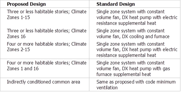
For dwelling unit space conditioning systems, the standard design heating subsystem is dependent on climate zone and number of habitable stories. For multifamily buildings with three habitable stories or less in Climate Zones 1-15 the space conditioning system is a heat pump. For multifamily buildings with three habitable stories or less in Climate Zone 16 the space conditioning system is an air conditioner with furnace. For multifamily buildings with four or more habitable stories in Climate Zones 2-15 the space conditioning system is a heat pump. For multifamily buildings with four or more habitable stories in Climate Zones 1 and 16 the space conditioning system is a dual-fuel heat pump.
When the standard design is a heat pump, the equipment used in the standard design building is an electric split-system heat pump with default ducts in the attic and a heating seasonal performance factor (HSPF/HSPF2) meeting the current Appliance Efficiency Regulations minimum efficiency for heat pumps. The standard design heat-pump compressor size is determined by the compliance software as the larger of the compressor size calculated for air-conditioning load, or the compressor with a 47°F rating that is 75 percent of the heating load (at the heating design temperature).
When the standard design is a gas heating system, the equipment used in the standard design building is a gas furnace (or propane if natural gas is not available) with default ducts in the attic and an annual fuel utilization efficiency (AFUE) meeting the Appliance Efficiency Regulations minimum efficiency for central systems.
See Table 23: HVAC Heating Equipment Types and Table 24: Heat Pump Equipment Types for complete details on heating systems noted above.
Table 22: Standard Design Dwelling Unit Heating System
|
Proposed Design |
Standard Design |
|
Three or less habitable stories; Climate Zones 1-15 |
Single zone system with constant volume fan, no economizer, DX heat pump with electric resistance supplemental heat |
|
Three or less habitable stories; Climate Zones 16 |
Single zone system with constant volume fan, no economizer, DX cooling and furnace |
|
Four or more habitable stories; Climate Zones 2-15 |
Single zone system with constant volume fan, no economizer, DX heat pump with electric resistance supplemental heat |
|
Four or more habitable stories; Climate Zones 1 and 16 |
Single zone system with constant volume fan, no economizer, DX heat pump with gas furnace supplemental heat |
Source: California Energy Commission
Verification and Reporting
The proposed heating system type and rated efficiency are reported in the compliance documentation on the LMCC or NRCC. For heat pumps, which are supplemented by electric resistance backup heating, the HERS-verified rated heating capacity of each proposed heat pump is reported on the LMCC or NRCC. Installed capacities must be equal to or larger than the capacities reported for modeled at 47° and 17° (RA 3.4.4.2).
Table 23: HVAC Heating Equipment Types
|
Name |
Heating Equipment Description |
|
CntrlFurnace |
Gas- or oil-fired central furnaces, propane furnaces, or heating equipment considered equivalent to a gas-fired central furnace, such as wood stoves that qualify for the wood heat exceptional method. Gas fan-type central furnaces have a minimum AFUE=80%. Distribution can be gravity flow or use any of the ducted systems. |
|
PkgGasFurnace |
The furnace side of a packaged air-conditioning system. Packaged gas or propane furnaces have a minimum AFUE=81%. Distribution can be any of the ducted systems. |
|
WallFurnace Gravity |
Noncentral gas- or oil-fired wall furnace, gravity flow. Equipment has varying efficiency requirements by capacity. Distribution is ductless. |
|
WallFurnace Fan |
Noncentral gas- or oil-fired wall furnace, fan-forced. Equipment has varying efficiency requirements by capacity. Distribution is ductless. |
|
FloorFurnace |
Noncentral gas- or oil-fired floor furnace. Equipment has varying efficiency requirements by capacity. Distribution is ductless. |
|
RoomHeater |
Noncentral gas- or oil-fired room heaters. Noncentral gas- or oil-fired wall furnace, gravity flow. Equipment has varying efficiency requirements by capacity. Distribution is ductless. |
|
WoodHeat |
Wood-fired stove. In areas with no natural gas available, a wood-heating system with any backup heating system is allowed to be installed if exceptional method criteria described in the Residential Compliance Manual are met. |
|
Boiler |
Gas or oil boilers. Distribution systems can be radiant, baseboard, or any of the ducted systems. Boiler may be specified for dedicated hydronic systems. Systems in which the boiler provides space heating and fires an indirect gas water heater (IndGas) may be listed as Boiler/CombHydro Boiler and is listed under “Equipment Type” in the HVAC Systems listing. |
|
Electric |
All electric heating systems other than space-conditioning heat pumps. Included are electric resistance heaters, electric boilers, and storage water heat pumps (air-water) (StoHP). Distribution system can be radiant, baseboard, or any of the ducted systems. |
|
CombHydro |
Water-heating system can be any gas water heater. Distribution systems can be radiant, baseboard, or any of the ducted systems and can be used with any of the terminal units (FanCoil, RadiantFlr, Baseboard, and FanConv). |
|
SZDFHP |
Single-zone system with constant volume fan, direct expansion heat pump cooling and heating, and gas supplemental heating. |
|
FPFC |
Four-pipe fan coil (FPFC) |
Source: California Energy Commission
Table 24: Heat Pump Equipment Types
|
Name |
|
|
SplitHeatPump |
Central split heat pump system. Distribution system is one of the ducted systems. |
|
SDHV SplitHeat Pump |
Small duct, high velocity, central split-system that produces at least 1.2 inches of external static pressure when operated at the certified air volume rate of 220–350 CFM per rated ton of cooling and uses high-velocity room outlets generally greater than 1,000 fpm that have less than 6.0 square inches of free area. |
|
Ductless MiniSplit HeatPump |
A heat pump system that has an outdoor section and one or more ductless indoor sections. The indoor section(s) cycle on and off in unison in response to an indoor thermostat. |
|
Ductless MultiSplit HeatPump |
A heat pump system that has an outdoor section and two or more ductless indoor sections. The indoor sections operate independently and can be used to condition multiple zones in response to multiple indoor thermostats. |
|
DuctlessVRF HeatPump |
A variable-refrigerant-flow (VRF) heat pump system that has one or more outdoor sections and two or more ductless indoor sections. The indoor sections operate independently and can be used to condition multiple zones in response to multiple indoor thermostats. |
|
PkgHeatPump |
Central packaged heat pump systems. Central packaged heat pumps are heat pumps in which the blower, coils, and compressor are contained in a single package, powered by single-phase electric current, air-cooled, and rated below 65,000 Btu/h. The distribution system is one of the ducted systems. |
|
RoomHeatPump |
Noncentral room air-conditioning systems. These include packaged terminal (commonly called “through-the-wall”) units and any other ductless heat pump systems. |
|
SglPkgVertHeatPump |
Single-package vertical heat pump. This is a package air conditioner that uses reverse cycle refrigeration as the prime heat source and may include secondary supplemental heating by means of electrical resistance. |
|
PkgTermHeatPump |
Packaged terminal heat pump. This is a package terminal air conditioner that uses reverse cycle refrigeration as the prime heat source; has a supplementary heating source available, with the choice of electric resistant heat; and is industrial equipment. |
|
DuctedMiniSplitHeat Pump |
Ducted mini-split heat pump is a system that has an outdoor section and one or more ducted indoor sections. The indoor section(s) cycle on and off in unison in response to an indoor thermostat. |
|
DuctedMultiSplitHeat Pump |
Ducted multi-split heat pump is a system that has a single outdoor section, and two or more ducted indoor sections. The indoor sections operate independently and can be used to condition multiple zones in response to multiple indoor thermostats. |
|
Ducted+DuctlessMulti SplitHeatPump |
Multi-split heat pump system with a combination of ducted and ductless indoor units. |
|
AirToWater HeatPump |
An indoor conditioning coil, a compressor, and a refrigerant-to-water heat exchanger that provides heating and cooling functions. Also, able to heat domestic hot water. |
|
Ground Source HeatPump |
An indoor conditioning coil with air-moving means, a compressor, and a refrigerant-to-ground heat exchanger that provides heating, cooling, or heating and cooling functions. May also have the ability to heat domestic hot water. |
|
Variable Capacity Heat Pump |
VCHP — Meets all the requirements of the VCHP Compliance Option or meets performance values specified in the Northeast Energy Efficiency Partnerships, Inc. (NEEP) database for a detailed analysis. |
|
SZDFHP |
Single-zone system with constant volume fan, direct expansion heat pump cooling and heating, and gas supplemental heating. |
|
CHPWH |
Central heat pump water heater systems including primary heating equipment, primary heating storage volume, location, secondary heating equipment, secondary heating storage volume, set point controls, and the way in which the components are plumbed. |
Source: California Energy Commission
Verified Heating Seasonal Performance Factor (HSPF/HSPF2)
Proposed Design
The compliance software allows the user to specify the HSPF/HSPF2 value for heat pump equipment. A conversion factor is used to convert HSPF to HSPF2 ratings for modeling. For split-system, small-duct high-velocity, and space-constrained equipment, the conversion factor is 0.85. For single-package equipment, the conversion factor is 0.84.
Standard Design
The standard design is the minimum allowable HSPF for the type of heat pump equipment modeled in the proposed design, based on the applicable Appliance Efficiency Regulations. For central-heating and cooling equipment, the minimum efficiency is 8.0 HSPF/6.7 HSPF2 for packaged heat pumps or 8.2 HSPF/7.5 HSPF2 for split heat pumps.
Verification and Reporting
If an HSPF/HSPF2 for the proposed design is higher than the default minimum efficiency modeled in compliance software, the HSPF/HSPF2 requires field verification. The HSPF/HSPF2 rating is verified using rating data from the Air-Conditioning, Heating, and Refrigeration Institute (AHRI) Directory of Certified Product Performance website or another directory of certified product performance ratings approved by the CEC for determining compliance. Verified SEER/SEER2 is reported in the HERS-required verification listings on the LMCC.
Combined Hydronic Space/Water Heating
Combined hydronic space/water heating is a system whereby a water heater is used to provide space heating and water heating. Dedicated hydronic space-heating systems are also a modeling capability. Space-heating terminals may include fan coils, baseboards, and radiant floors.
For combined hydronic systems, the water-heating portion is modeled normally. For space heating, an effective AFUE is calculated for gas water heaters. For electric water heaters, an effective HSPF/HSPF2 is calculated. The procedures for calculating the effective AFUE or HSPF/HSPF2 are described below.
Combined hydronic space-conditioning cannot be combined with heat pump water heating or with zonal control credit.
Proposed Design
When a fan coil is used to distribute heat, the fan energy and the heat contribution of the fan motor must be considered. The algorithms for fans used in combined hydronic systems are the same as those used for gas furnaces and are described in Appendix G.
If a large fan coil is used and air-distribution ducts are in the attic, crawl space, or other unconditioned space, the efficiency of the air-distribution system must be determined using methods consistent with those described in Chapter 6.8.3 Distribution Systems. Duct efficiency is accounted for when the distribution type is ducted.
Commercial or Consumer Storage Gas Water Heater
When storage gas water heaters are used in combined hydronic applications, the effective AFUE is given by the following equation:
Equation 7

Where:
AFUEeff - The effective AFUE of the gas water heater in satisfying the space heating load.
RE - The recovery efficiency (or thermal efficiency) of the gas storage water heater. A default value of 0.70 may be assumed if the recovery efficiency is unknown. This value is generally available from the CEC appliance directory.
PL - Pipe losses (kBtu/h). This can be assumed to be zero when less than 10 feet of piping between the water heater storage tank and the fan coil or other heating elements are in unconditioned space.
RI - The rated input of the gas water heater (kBtu/h) available from the CEC appliance directory.
Instantaneous Gas Water Heater
When instantaneous gas water heaters are used in combined hydronic applications, the effective AFUE is given by the following equation:
Equation 8

Where:
AFUEeff - The effective AFUE of the gas water heater in satisfying the space heating load.
UEF - The rated uniform energy factor of the instantaneous gas water heater.
Storage Electric Water Heater
The HSPF of storage water heaters used for space heating in a combined hydronic system is given by the following equations.
Equation 9

Where:
HSPFeff - The effective HSPF of the electric water heater in satisfying the space-heating load.
PL - Pipe losses (kBtu/h). Assumed zero when less than 10 feet of piping between the water heater storage tank and the fan coil or other heating elements are in unconditioned space.
kWi - The kilowatts of input to the water heater available from the CEC’s appliance directory.
Standard Design
When a hydronic system is proposed to use electricity is used for heating, the heating equipment for the standard design is an electric split-system heat pump with an HSPF/HSPF2 meeting the Appliance Efficiency Regulations requirements for split-systems. The standard design heat pump compressor size is determined by the compliance software based on the compressor size calculated for the air-conditioning system.
When electricity is not used for heating, the equipment used in the standard design building is a gas furnace (or propane if natural gas is not available) with default ducts in the attic and an AFUE meeting the Appliance Efficiency Regulations minimum efficiency for central systems. When a proposed design uses electric and non-electric heat, the standard design is a gas furnace.
Special Systems — Hydronic Distribution Systems and Terminals
Hydronic distribution systems in unconditioned spaces are included in the building model to account for heat loss to these unconditioned spaces. Heat loss is affected by the length of piping in unconditioned spaces, pipe size, pipe insulation thickness, and pipe insulation R-value.
Proposed Design
This listing is completed for hydronic systems that have more than 10 feet of piping (plan view) in unconditioned space. As many rows as necessary may be used to describe the piping system.
Standard Design
The standard design is established for a hydronic system in the same way as for a central system, as described in Chapter 6.8.1 Heating Subsystems.
Verification and Reporting
A hydronic or combined hydronic system is reported on the LMCC or NRCC.
Other information reported includes:
•Piping Run Length (ft). The length (plan view) of distribution pipe in unconditioned space, in feet, between the primary heating/cooling source and the point of distribution.
•Nominal Pipe Size (in.). The nominal (as opposed to true) pipe diameter in inches.
•Insulation Thickness (in.). The thickness of the insulation in inches. Enter "none" if the pipe is uninsulated.
Insulation R-value (hr-ft2-°F/Btu). The installed R-value of the pipe insulation. Minimum pipe insulation for hydronic systems is as specified in §160.4(f).
Ground-Source Heat Pump
A ground-source heat pump system, which uses the earth as a source of energy for heating and as a heat sink for energy when cooling, is simulated as a minimum efficiency split-system equivalent to the standard design with default duct conditions in place of the proposed system. The mandatory efficiencies for ground-source heat pumps are a minimum coefficient of performance (COP) for heating and EER/EER2 for cooling.
Air-to-Water Heat Pumps
Air-to-water heat pumps (AWHPs) must be listed in the Title 20 MAEDbS database. For the proposed design, fixed compressor speed AWHPs would be modeled equivalent to the prescriptive air source heat pump in heating and cooling operation. Variable compressor speed AWHPs would be treated with a 2% reduction in hourly heating energy use and an 8% reduction in hourly cooling energy use, relative to the prescriptive air source heat pump.
Variable Capacity Heat Pumps
The performance of variable capacity heat pumps (VCHP) varies widely depending on a number of factors.
A simplified compliance option is available. To use this compliance option, the VCHP must meet all the requirements of the VCHP Compliance Option.
For detailed analysis of VCHP, energy usage for VCHP systems shall be based on minimum and maximum cooling capacity and corresponding input power at hot ambient and mild ambient conditions. The minimum and maximum heating capacity and corresponding input power at cold and ambient conditions shall also be considered. These values are found in the Northeast Energy Efficiency Partnerships, Inc. (NEEP) database. The mandatory efficiencies of HSPF/HSPF2, SEER/SEER2, and EER/EER2 are also considered for verification purposes. These values shall be considered as follows, or through an approved method showing minimum energy equivalency.
VCHP performance at specific at a specific heating or cooling load is calculated by interpolating between the minimum and maximum performance indicated in the NEEP data. For outdoor conditions outside the range represented in the NEEP data, extrapolation, assuming a linear relationship, is used. To account for variations in indoor conditions, the algorithm applies the same variation as it does for single speed systems normalized to take out the effect of the outdoor temperature.
The operational capacity is defined by the combination of the heating or cooling load in the space, heat loss or gain due to duct losses, and heat gain due to air handler fan energy. When the capacity required of the VCHP to meet the building load and overcome duct losses is greater than the minimum capacity, it is assumed the VCHP operates continuously. When the required capacity is less than the minimum capacity, it is assumed that the VCHP is operating at minimum capacity and cycling. When the unit is cycled, a degradation coefficient of 0.25 shall be applied for both heating and cooling. Indoor airflow is assumed to modulate in proportion to the VCHP capacity.
If VCHP maximum heating capacity is insufficient to meet the load, it is assumed that the unmet portion of the load will be met by electric resistance heat. Defrost occurs between 35 F and 17 F outdoor temperature with electric resistance auxiliary heat assumed to compensate for heat lost during the defrost cycle. The crankcase heater serving multifamily zones is assumed to operate at 40 W whenever the temperature is below 50 F.
The cooling subsystem describes the equipment that supplies cooling to a space-conditioning system.
Proposed Design
Cooling subsystems are categorized according to the types shown in Table 25: HVAC Cooling Equipment Types (Other Than Heat Pumps)The user selects the type of cooling equipment and enters basic information to model the energy use of the equipment. Enter the cooling equipment type and additional information based on the equipment type and zoning, such as the SEER/SEER2 and EER/EER2. For some types of equipment, the user may also specify if the equipment has a multispeed compressor and if the system is zoned or not via checkboxes. For ducted cooling systems, the cooling airflow from the conditioned zone through the cooling coil is input as CFM per ton. The rated cooling capacity is not a compliance variable.
Until there is an approved compliance option for ductless heat pumps (ducted and ductless mini-split, and multi-split), these systems are simulated as a minimum efficiency split-system equivalent to the standard design with default duct conditions.
See chapters below for the details of specific inputs.
Standard Design
The cooling system for the standard design building is a nonzonal control system, split-system ducted cooling system, meeting the minimum requirements of the Appliance Efficiency Regulations. The standard design system shall assume verified refrigerant charge in Climate Zones 2 and 8–15 for all systems. Mandatory fan efficacy is assumed in all climate zones. For equipment not subjected to EER rating, the standard is 11.7 EER.
Table 25: HVAC Cooling Equipment Types (Other Than Heat Pumps)
|
Name |
Cooling Equipment Description |
|
NoCooling |
Entered when the proposed building is not cooled or when cooling is optional (to be installed at some future date). Both the standard design equivalent building and the proposed design use the same default system (refer to Chapter 6.8.5.3 No Cooling). |
|
SplitAirCond |
Split air-conditioning systems. Distribution system is one of the ducted systems. (Efficiency metric: SEER/SEER2 and EER/EER2) |
|
PkgAirCond |
Central packaged air-conditioning systems less than 65,000 Btu/h cooling capacity. Distribution system is one of the ducted systems. (Efficiency metric: SEER/SEER2 and EER/EER2) |
|
LrgPkgAirCond |
Large packaged air-conditioning systems rated at or above 65,000 Btu/h cooling capacity. Distribution system is one of the ducted systems. |
|
SDHVSplitAirCond |
Small-duct, high-velocity, split A/C system. |
|
DuctlessMiniSplitAirCond |
Ductless mini-split A/C system having an outdoor section and one or more indoor sections. The indoor sections cycle on and off in unison in response to an indoor thermostat. |
|
DuctlessMultiSplitAirCond |
Ductless multi-split A/C system having an outdoor section and two or more indoor sections. The indoor sections operate independently and can be used to condition multiple zones in response to multiple indoor thermostats. |
|
DuctlessVRFAirCond |
Ductless variable refrigerant flow (VRF) A/C system. |
|
SglPkgVertAirCond |
Single-packaged vertical A/C is a self-contained cooling system that is factory-assembled, is arranged vertically, can be mounted on the exterior or interior of a space and, can be installed through the wall. These units can be ducted or ductless. They are rated using ANSI/AHRI 390(I-P)-2003. |
|
PkgTermAirCond |
Packaged terminal A/C (PTAC) is a self-contained cooling system that is installed through the wall. These systems do not use ducts. They are rated using AHRI 310/380-2017. |
|
DuctedMiniSplitAirCond |
Ducted mini-split A/C system having an outdoor section and one or more indoor sections. The indoor sections cycle on and off in unison in response to an indoor thermostat. |
|
DuctedMultiSplitAirCond |
Ducted multi-split A/C system having an outdoor section and two or more indoor sections. The indoor sections operate independently and can be used to condition multiple zones in response to multiple indoor thermostats. |
|
Ducted+DuctlessMulti SplitAirCond |
Combination of ducted and ductless multi-split A/C system have an outdoor section and two or more indoor sections. The indoor sections operate independently and can be used to condition multiple zones in response to multiple indoor thermostats. |
|
RoomAirCond |
Room air conditioner is a self-contained cooling system that is installed through the wall. These systems do not use ducts. They are rated using ANSI/ASHRAE Standard 16-2016. Same as DuctlessSplitAirCond except that cooling is not supplied to each habitable space in the dwelling unit. |
|
EvapCondenser |
Evaporatively cooled condensers. A split mechanical system, with a water-cooled condenser coil. |
|
FPFC |
Four-pipe fan coil (FPFC) |
Source: California Energy Commission
Verification and Reporting
Information shown on the LMCC or NRCC includes cooling equipment type and cooling efficiency (SEER/SEER2 or EER/EER2 or both). Measures requiring verification (Table 26: Summary of Space Conditioning Measures Requiring Verification) are listed in the HERS verification section of the LMCC or NRCC.
Verified Refrigerant Charge or Fault Indicator Display
Proper refrigerant charge is necessary for electrically driven compressor air-conditioning systems to operate at full capacity and efficiency. Compliance software calculations set the compressor efficiency multiplier to 0.90 to account for the effect of improper refrigerant charge or 0.96 for proper charge.
Proposed Design
The compliance software allows the user to indicate if systems will have diagnostically tested refrigerant charge or a field-verified fault indicator display (FID). This allowance applies only to ducted split-systems and packaged air-conditioners and heat pumps.
Standard Design
The standard design building is modeled with either diagnostically tested refrigerant charge or a field-verified FID if the building is in Climate Zone 2 or 8–15, and refrigerant charge verification is required by §170.2(c)3B and Table 170.2-K for the proposed cooling system type.
Verification and Reporting
Refrigerant charge or FID require field verification or diagnostic testing and are reported in the HERS required verification listings on the LMCC or NRCC. Details on refrigerant charge measurement are discussed in Reference Residential Appendix RA3.2. Information on the requirements for FIDs is in Reference Joint Appendix JA6.1.
Table 26: Summary of Space Conditioning Measures Requiring Verification
|
Measure |
Description |
Procedures |
|
Verified Refrigerant Charge |
Air-cooled air-conditioners and air-source heat pumps must be tested diagnostically to verify that the system has the correct refrigerant charge. The system must also meet the system airflow requirement. |
RA1.2, RA3.2 |
|
Verified Fault Indicator Display |
A fault indicator display can be installed as an alternative to refrigerant charge testing. |
RA3.4.2 |
|
Verified System Airflow |
When compliance requires verified system airflow greater than or equal to a specified criterion. |
RA3.3 |
|
Verified Air-Handling Unit Fan Efficacy |
To verify that fan efficacy (watt/CFM) is less than or equal to a specified criterion. |
RA3.3 |
|
Verified HSPF/HSPF2, SEER/SEER2 or EER/EER2 |
Credit for increased efficiency by installation of specific air-conditioner or heat pump models. |
RA3.4.4.1 |
|
Verified Heat Pump Capacity |
Optional verification of heat-pump system capacity. |
RA3.4.4.2 |
|
Evaporatively Cooled Condensers |
Must be combined with duct leakage testing, refrigerant charge, and verified EER/EER2. |
RA3.1.4.3, RA3.2, RA3.4.3, RA3.4.4.1 |
|
Whole-House Fan |
When verification of the whole-house fan is selected or required, airflow, watt draw, and capacity are verified. |
RA3.9 |
|
Central Fan Ventilation Cooling System |
When compliance includes this type of ventilation cooling, airflow and fan efficacy are verified. |
RA3.3.4 |
Source: California Energy Commission
Verified System Airflow
Adequate airflow to the conditioned space is required to allow ducted air-conditioning systems to operate at full efficiency and capacity. Efficiency is achieved by the air-distribution system design by improving the efficiency of motors or by designing and installing air distribution systems that have less resistance to airflow. Compliance software calculations account for the effect of airflow on sensible heat ratio and compressor efficiency.
For systems other than small-duct, high-velocity types, a value less than 350 CFM/ton (minimum 150 CFM/ton) is a valid input only if zonally controlled equipment is selected and multispeed compressor is not selected. Inputs less than 350 CFM/ton for zonally controlled systems require verification using procedures in Reference Appendices, Residential Appendix RA3.3.
§160.3(b)5L requires verification that the central air-handling unit airflow rate is greater than or equal to 350 CFM/ton for systems other than small-duct, high-velocity types or 250 CFM/ton for small-duct, high-velocity systems. Values greater than the required CFM/ton may be input for compliance credit, which requires diagnostic testing using procedures in Reference Appendices, Residential Appendix RA3.3.
For single-zone systems:
•As an alternative to verification of 350 CFM/ton for systems other than small-duct, high-velocity types or 250 CFM/ton for small-duct, high-velocity systems, HERS verification of a return duct design that conforms to the specification given in Table 160.3-A or B may be used to demonstrate compliance.
•The return duct design alternative is not an input to the compliance software but must be documented on the certificate of installation.
•If a value greater than 350 CFM/ton for systems other than small-duct, high-velocity types or greater than 250 CFM/ton for small-duct, high-velocity systems is modeled for compliance credit, the alternative return duct design method using Table 160.3-A or B is not allowed for demonstrating compliance.
•Variable capacity systems including multispeed and variable-speed compressor systems must verify airflow rate (CFM/ton) for system operation at the maximum compressor speed and the maximum air handler fan speed.
For zonally controlled systems:
•The Table 160.3-A or B return duct design alternative is not allowed for zonally controlled systems.
•Variable capacity systems including multispeed, variable-speed, and single-speed compressor systems must all verify airflow rate (CFM/ton) by operating the system at maximum compressor capacity and maximum system fan speed in every zonal control mode with all zones calling for conditioning.
•Single-speed compressor systems must also verify airflow rate (CFM/ton) in every zonal control mode.
•For systems that input less than 350 CFM/ton, HERS verification compliance cannot use group sampling.
Proposed Design
The default cooling airflow is 150 CFM/ton for a system with “zonally controlled” selected and “multispeed compressor” not selected (single-speed). Users may model airflow for these systems greater than or equal to 150 CFM/ton, which must be verified using the procedures in Reference Appendices, Residential Appendix RA3.3. Inputs less than the rates required by §160.3(b)5L will be penalized in the compliance calculation.
The default cooling airflow is 350 CFM/ton for systems other than small-duct, high-velocity types or 250 CFM/ton for small-duct, high-velocity systems. Users may model a higher-than-default airflow for these systems and receive credit in the compliance calculation if greater-than-default system airflow is diagnostically tested using the procedures of Reference Appendices, Residential Appendix RA3.3.
Standard Design
The standard design shall assume a system that complies with mandatory (§160.3) and prescriptive (§170.2) requirements for the applicable climate zone.
Verification and Reporting
The airflow rate verification compliance target (CFM or CFM/ton) is reported in the HERS required verification listings of the LMCC or NRCC. When there is no cooling system, it is reported on the LMCC or NRCC as a special feature.
Verified Air-Handling Unit Fan Efficacy
The mandatory requirement in §160.3(b)5L is for an air-handling unit fan efficacy equal to or less than 0.45 watts/CFM for gas furnace air-handling units, 0.58 watts/CFM for air-handling units that are not gas furnaces, and 0.62 W/CFM for small-duct, high-velocity systems as verified by a HERS rater. Users may model a lower fan efficacy (W/CFM) and receive credit in the compliance calculation if the proposed fan efficacy value is diagnostically tested using the procedures in Reference Appendices, Residential Appendix RA3.3.
For single-zone systems:
•Installers may elect to use an alternative to HERS verification of the watts/CFM required by §160.3(b)5L: HERS verification of a return duct design that conforms to the specification given in Table 160.3-A or B.
•The return duct design alternative is not an input to the compliance software but must be documented on the certificate of installation.
•If a value less than the watts/CFM required by §160.3(b)5L is modeled by the compliance software user for compliance credit, the alternative return duct design method using Table 160.3-A or B is not allowed for use in demonstrating compliance.
•Multispeed or variable-speed compressor systems must verify fan efficacy (watt/CFM) for system operation at the maximum compressor speed and the maximum air handler fan speed.
For zonally controlled systems:
•The Table 160.3-A or B return duct design alternative is not allowed for zonally controlled systems.
•Variable capacity systems including multispeed, variable-speed, and single-speed compressor systems must all verify fan efficacy (watt/CFM) by operating the system at maximum compressor capacity and maximum system fan speed with all zones calling for conditioning.
•Single-speed compressor systems must verify fan efficacy in every zonal control mode.
Proposed Design
The compliance software shall allow the user to enter the fan efficacy. The default mandatory value is 0.45, 0.58, or 0.62 W/CFM, depending on the applicable system type. However, users may specify a lower value and receive credit in the compliance calculation if verified and diagnostically tested using the procedures of Reference Appendices, Residential Appendix RA3.3.
If no cooling system is installed, a default value of 0.45 W/CFM is assumed.
Standard Design
The standard design shall assume a verified fan efficacy complying with the mandatory requirement of equal to or less than the following:
•0.45 W/CFM for gas furnace air-handling units, as well as air-handling unit that are not gas furnaces and have a capacity less than 54,000 BTU/h
•0.58 W/CFM for air-handling units that are not gas furnaces and have a capacity greater than or equal to 54,000 BTU/h
•0.62 W/CFM for small duct high velocity forced air systems.
Verification and Reporting
For user inputs lower than the default mandatory requirement, fan efficacy is reported in the HERS-required verification listings of the LMCC.
For default mandatory 0.45 or 0.58 watts/cfm, the choice of either fan efficacy or alternative return duct design according to Table 160.3-A or B is reported in the HERS-required verification listings of the LMCC or NRCC.
No cooling system is reported as a special feature on the LMCC or NRCC.
Verified Energy Efficiency Ratio (EER/EER2) For Buildings Up To Three Habitable Stories
Proposed Design
Compliance software shall allow the user the option to enter an EER/EER2 rating for central cooling equipment. For equipment that is rated only with an EER/EER2 (room air-conditioners), the user will enter the EER/EER2. The Appliance Efficiency Regulations require a minimum SEER/SEER2 and EER/EER2 for central cooling equipment. Only if a value higher than a default minimum EER/EER2 is used is it reported as a HERS-verified measure. A conversion factor is used to convert EER to EER2 ratings for modeling. For all air conditioners the conversion factor is 0.96.
Standard Design
The standard design is based on the default minimum efficiency EER/EER2 for the type of cooling equipment modeled in the proposed design, based on the applicable Appliance Efficiency Regulations. The standard design for central air-conditioning equipment is 11.7 EER/11.2 EER2 for split systems.
Verification and Reporting
If an EER/EER2 higher than the default minimum efficiency is modeled in compliance software, the EER/EER2 requires field verification. The EER/EER2 rating is verified using rating data from AHRI Directory of Certified Product Performance website or another directory of certified product performance ratings approved by the CEC for determining compliance. Verified EER is reported in the HERS-required verification listings on the LMCC.
Verified Seasonal Energy Efficiency Ratio (SEER/SEER2) For Buildings Up To Three Habitable Stories
Proposed Design
The compliance software allows the user to specify the SEER/SEER2 value. A conversion factor is used to convert SEER to SEER2 ratings for modeling. For split-system equipment the conversion factor is 0.95; for single-package equipment the conversion factor is 0.96; for small-duct high-velocity the conversion factor is 1.00; and for space-constrained equipment the conversion factor is 0.99.
Standard Design
The standard design is based on the default minimum efficiency SEER/SEER2 for the type of cooling equipment modeled in the proposed design, based on the applicable Appliance Efficiency Regulations. For central-cooling equipment, the minimum efficiency is 14 SEER/13.8 SEER2 for split systems.
Verification and Reporting
If a SEER/SEER2 higher than the default minimum efficiency is modeled in compliance software, the SEER/SEER2 requires field verification. The higher-than-minimum SEER/SEER2 rating is verified using rating data from AHRI Directory of Certified Product Performance website or another directory of certified product performance ratings approved by the CEC for determining compliance. Verified SEER/SEER2 is reported in the HERS-required verification listings on the LMCC.
Verified Evaporatively Cooled Condensers For Buildings Up To Three Habitable Stories
Proposed Design
Compliance software shall allow users to specify an evaporatively cooled condensing unit. The installation must comply with the requirements of Reference Appendices, Residential Appendix RA4.3.2 to ensure the predicted energy savings are achieved. This credit must be combined with verified refrigerant charge testing, EER/EER2, and duct leakage testing.
Standard Design
The standard design is based on a split-system air-conditioner meeting the requirements of §170.2(c) and Table 170.2-K.
Verification and Reporting
An evaporatively-cooled condensing unit, verified EER/EER2, and duct leakage testing are reported in the HERS required verification listings on the LMCC.
Evaporative cooling technology is best suited for dry climates where direct, indirect, or indirect-direct cooling of the supply air stream can occur without compromising indoor comfort. Direct evaporative coolers are the most common system type available but provide less comfort and deliver more moisture to the indoor space. They are assumed equivalent to a minimum split-system air-conditioner.
Proposed Design
Compliance software shall allow users to specify one of three types of evaporative cooling: (1) direct evaporative cooler, the most commonly available system type; (2) indirect; or (3) indirect-direct. Product specifications and other modeling details are found in the CEC appliance directory for evaporative cooling. Direct system types are assigned an efficiency of 14 SEER (or minimum appliance efficiency standard for split-system cooling). The default system type is evaporative direct. For indirect or indirect-direct, select the appropriate type from the CEC appliance directory and input a 13 EER as well as the airflow and media saturation effectiveness or cooling effectiveness from the CEC appliance directory.
Standard Design
The standard design is based on a split-system air-conditioner meeting the requirements of §170.2(c) and Table 170.2-K.
Verification and Reporting
When a direct evaporative cooling system is modeled, the system type and minimum efficiency are shown in the appropriate section of the LMCC. When indirect or indirect-direct evaporative cooling is modeled, the EER/EER2 verification is shown in the HERS verification section of the LMCC along with the system type, airflow, and system effectiveness.
If multiple HVAC distribution systems serve a building, each system, and the conditioned space it serves may be modeled in detail separately or the systems may be aggregated and modeled as one large system. If the systems are aggregated, they must be the same type, and all meet the same minimum specifications.
For duct efficiency calculations, the supply duct begins at the exit from the furnace or air-handler cabinet.
Distribution Type
Fan-powered, ducted distribution systems can be used with most heating or cooling systems. When ducted systems are used with furnaces, boilers, or combined hydronic/water heating systems, the electricity used by the fan is calculated. R-value and duct location are specified when a ducted system is specified.
Proposed Design
The compliance software shall allow the user to select from the basic types of HVAC distribution systems and locations listed in Table 27: HVAC Distribution Type and Location Descriptors. For ducted systems, the default location of the HVAC ducts and the air handler are in conditioned space for multifamily buildings and in the attic for all other buildings.
Table 27: HVAC Distribution Type and Location Descriptors
|
Name |
HVAC Distribution Type and Location Description |
|
Ducts located in attic (ventilated and unventilated) |
Ducts located overhead in the attic space. |
|
Ducts located in a crawl space |
Ducts located under floor in the crawl space. |
|
Ducts located in a garage |
Ducts located in an unconditioned garage space. |
|
Ducts located within the conditioned space (except < 12 linear ft) |
Ducts located within the conditioned floor space except for less than 12 linear feet of duct, furnace cabinet, and plenums — typically an HVAC unit in the garage mounted on return box with all other ducts in conditioned space. |
|
Ducts located entirely in conditioned space |
HVAC unit or systems with all HVAC ducts (supply and return) within the conditioned floor space. Location of ducts in conditioned space eliminates conduction losses but does not change losses due to leakage. Leakage either from ducts that are not tested for leakage or from sealed ducts is modeled as leakage to outside the conditioned space. |
|
Distribution system without ducts (none) |
Air-distribution systems without ducts such as ductless split-system air-conditioners and heat pumps, window air-conditioners, through-the-wall heat pumps, wall furnaces, floor furnaces, radiant electric panels, combined hydronic heating equipment, electric baseboards, or hydronic baseboard finned-tube natural convection systems, etc. |
|
Ducts located in outdoor locations |
Ducts in exposed locations outdoors. |
|
Verified low-leakage ducts located entirely in conditioned space |
Duct systems for which air leakage to outside is equal to or less than 25 CFM when measured in accordance with Reference Residential Appendix RA3.1.4.3.8. |
|
Ducts located in multiple places |
Ducts with different supply and return duct locations. |
Source: California Energy Commission
Table 28: Summary of Verified Distribution Systems
|
Measure |
Description |
Procedures |
|
Multifamily Buildings Up to Three Habitable Stories Verified Duct Sealing |
Mandatory measures require that space-conditioning ducts be sealed. Field verification and diagnostic testing are required to verify that approved duct system materials are used and that duct leakage meets the specified criteria. |
RA3.1.4.3 |
|
Multifamily Buildings Up to Three Habitable Stories Verified Duct Location, Reduced Surface Area and R-value |
Compliance credit can be taken for improved supply duct location, reduced surface area, and R-value. Field verification is required to verify that the duct system was installed according to the duct design, including location, size and length of ducts, duct insulation R-value, and installation of buried ducts.1 For buried duct measures, verified QII is required, as well as duct sealing. |
RA3.1.4.1, 3.1.4.1.1 |
|
Multifamily Buildings Up to Three Habitable Stories Low-Leakage Ducts in Conditioned Space |
When the Energy Code specify use of the procedures in Reference Appendices, Residential Appendix RA3.1.4.3.8 to determine if the space-conditioning system ducts are entirely in directly conditioned space, the duct system location is verified by diagnostic testing. Compliance credit can be taken for verified duct systems with low air leakage to the outside when measured in accordance with Reference Appendices, Residential Appendix RA3.1.4.3.8. Field verification for ducts in conditioned space is required. Duct sealing is required. |
RA3.1.4.3.8 |
|
Multifamily Buildings Up to Three Habitable Stories Hydronic Delivery in Conditioned Space |
Compliance credit can be taken for hydronic delivery systems with no ducting or piping in unconditioned space. For radiant ceiling panels, the verifications in Reference Appendices, Residential Appendix RA3.4.5 must be completed to qualify. |
RA3.4.5 |
|
Multifamily Buildings Up to Three Habitable Stories Low-Leakage Air-Handling Units |
Compliance credit can be taken for installing a factory-sealed air-handling unit tested by the manufacturer and certified to the CEC to have met the requirements for a low-leakage air-handling unit. Field verification of the air handler model number is required. Duct sealing is required. |
RA3.1.4.3.9 |
|
Multifamily Buildings Up to Three Habitable Stories Verified Return Duct Design |
Verification to confirm that the return duct design conforms to the criteria given in Table 160.3-A or Table 160.3-B. as an alternative to meeting 0.45 or 0.58 W/CFM fan efficacy of §160.3(b)5L. |
RA3.1.4.4 |
|
Multifamily Buildings Up to Three Habitable Stories Verified Bypass Duct Condition |
Verification to determine if system is zonally controlled and confirm that bypass ducts condition modeled matches installation. |
RA3.1.4.6 |
1. Compliance credit for increased duct insulation R-value (not buried ducts) may be taken without field verification if the R-value is the same throughout the building, and for supply ducts located in crawl spaces and garages where all supply registers are either in the floor or within 2 feet of the floor. If these conditions are met, HERS rater verification is not required.
Source: California Energy Commission
The compliance software will allow users to select default assumptions or specify any of the verified or diagnostically tested HVAC distribution system conditions in the proposed design (Table 28: Summary of Verified Distribution Systems), including duct leakage target, R-value, supply and return duct area, diameter, and location.
Standard Design
The standard heating and cooling system for central systems is modeled with air distribution ducts located as described in Table 29: Summary of Standard Design Duct Location for Buildings Up to Three Habitable StoriesTable 26,, with duct leakage as specified in Table 37: Duct/Air Handler Leakage. The standard design duct insulation is determined by Table 170.2-K as R-6 in Climate Zones 3 and 5–7, and R-8 in Climate Zones 1, 2, 4, and 8–16. The standard design building is assumed to have the same number of stories as the proposed design for determining the duct efficiency.
Table 29: Summary of Standard
Design Duct Location for Buildings
Up to Three Habitable Stories
|
Configuration of the |
Standard Design Duct Location |
Detailed Specifications |
|
Attic over the dwelling unit |
Ducts and air handler located in the attic |
Ducts sealed (mandatory requirement) No credit for verified R-value, location, or duct design |
|
No attic but crawl space or basement |
Ducts and air handler located in the crawl space or basement |
Ducts sealed (mandatory requirement) No credit for verified R-value, location, or duct design |
|
Multifamily buildings with no attic, crawl space or basement |
Ducts and air handler located indoors |
Ducts sealed (mandatory requirement) No credit for verified R-value, location, or duct design |
This table is applicable only when the standard design system has air-distribution ducts
Source: California Energy Commission
Verification and Reporting
Distribution type, location, R-value, and the determination of whether tested and sealed will be shown on the LMCC. If there are no ducts, the absence of ducts is shown as a special feature on the LMCC. Any duct location other than attic (for example, crawl space) is shown as a special feature on the LMCC. Ducts in crawl space or the basement shall include a special feature note if supply registers are within 2 feet of the floor. Measures that require HERS verification will be shown in the HERS required verification section of the LMCC.
Duct Location For Buildings Up to Three Habitable Stories
Duct location determines the external temperature for duct conduction losses, the temperature for return leaks, and the thermal regain of duct losses.
Proposed Design
If any part of the supply or return duct system is in an unconditioned attic, that entire duct system is modeled with an attic location. If no part of the supply or return duct system is located in the attic, but the duct system is not entirely in conditioned space, it is modeled in the unconditioned zone, which contains the largest fraction of the surface area. If the supply or return duct system is entirely in conditioned space, the duct system is modeled in conditioned space.
For ducted HVAC systems with some or all ducts in unconditioned space, the user specifies the R-value and surface area of supply and return ducts and the duct location.
Duct location and areas other than the defaults shown in Table 29: Summary of Standard Design Duct Location for Buildings Up to Three Habitable Stories may be used following the verification procedures in Reference Appendices, Residential Appendix RA3.1.4.1.
Standard Design
The standard design duct location is determined from the building conditions (Table 26).
Verification and Reporting
Duct location is reported on the LMCC. Ducts entirely in conditioned space and verified low-leakage ducts entirely in conditioned space are reported in the HERS-required verification listing on the LMCC.
Default duct locations are shown in Table 30: Location of Default Duct Surface Area. The duct surface area for crawl space and basement applies only to buildings or zones with all ducts installed in the crawl space or basement. If the duct is installed in locations other than crawl space or basement, the default duct location is “Other.” For dwelling units with two or more stories, 35 percent of the default duct area may be assumed to be in conditioned space, as shown in Table 30: Location of Default Duct Surface Area.
The surface area of ducts in conditioned space is ignored in calculating conduction losses.
Table 30: Location of Default Duct Surface Area
|
One story |
Two or more stories | |
|
All in crawl space |
100% crawl space |
65% crawl space, 35% conditioned space |
|
All in basement |
100% basement |
65% basement, 35% conditioned space |
|
Other |
100% attic |
65% attic, 35% conditioned space |
Source: California Energy Commission
Duct Surface Area
The supply-side and return-side duct surface areas are treated separately in distribution efficiency calculations. The duct surface area is determined using the following methods.
Default Return Duct Surface Area
Default return duct surface area is calculated using:

Where Kr (return duct surface area coefficient) is 0.05 for one-story dwelling units and 0.1 for dwelling units with two or more stories and Afloor is the floor area. Ar,out is the surface area of the return duct.
Default Supply Duct Surface Area
Standard Design
The standard design and default proposed design supply duct surface area is calculated using Equation 5

Where Ks (supply duct surface area coefficient) is 1 for one-story buildings and 0.65 for two or more stories and Afloor is the floor area. As,out is the surface area of the return duct.
Supply Duct Surface Area for Less Than 12 feet of Duct in Unconditioned Space
Proposed Design
For proposed design HVAC systems with air handlers outside the conditioned space but with less than 12 linear feet of duct outside the conditioned space, including air handler and plenum, the supply duct surface area outside the conditioned space is calculated using Equation 12. The return duct area remains the default for this case.

Diagnostic Duct Surface Area for Buildings Up to Three Habitable Stories
Proposed designs may claim credit for reduced surface area using the procedures in Reference Appendices, Residential Appendix RA3.1.4.1.
The surface area of each duct system segment shall be calculated based on the associated inside dimensions and length. The total supply surface area in each unconditioned location (attic, attic with radiant barrier, crawl space, basement, other) is the sum of the area of all duct segments in that location. The surface area of ducts completely inside conditioned space need not be input in the compliance software and is not included in the calculation of duct system efficiency. The area of ducts in floor cavities or vertical chases that are surrounded by conditioned space and separated from unconditioned space with draft stops are also not included. The compliance software assumes the user input duct system area is 85 percent of the total duct system area. The other 15 percent is assumed to be air handler, plenum, and connectors. Because of this, the total duct system area used in the building simulation is:
Simulated Duct System Area = 1.1765 multiplied by the total user entered duct system area
Bypass Duct
§170.2(c)3C prohibits use of bypass ducts unless a bypass duct is otherwise specified on the certificate of compliance. A bypass duct may be needed for some single-speed outdoor condensing unit systems. The compliance software allows users to specify a bypass duct for the system. Selection of a bypass duct does not trigger changes in the ACM modeling defaults, but verification by a HERS rater is required to use the procedure in Reference Appendices, Residential Appendix RA3.1.4.6.
Specification of a zonally controlled system with a single-speed condensing unit will trigger a default airflow rate value of 150 CFM/ton for the calculations. User input less than 350 CFM/ton reduces the compliance margin as compared to systems that model 350 CFM/ton as described in Chapter 6.8.2.2 Verified System Airflow.
Proposed Design
Compliance software shall allow users to specify whether a bypass duct is used for a zonally controlled forced air system.
Standard Design
The standard design is based on a split-system air-conditioner meeting the requirements of §170.2 and Table 170.2-K. The system is not a zonally controlled system.
Verification and Reporting
An HVAC system with zonal control, and the determination of whether the system is assumed to have a bypass duct or have no bypass duct, is reported in the HERS-required verification listings on the LMCC or NRCC.
Duct System Insulation
For conduction calculations in the standard and proposed designs, 85 percent of the supply and return duct surface is assumed duct material at the related specified R-value, and 15 percent is assumed air handler, plenum, connectors, and other components at the mandatory minimum R-value.
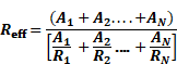
The area weighted effective R-value is calculated by the compliance software using Equation 7, including each segment of the duct system that has a different R-value.
Equation 13
Where:
•Reff - Area weighted effective R-value of duct system for use in calculating
duct efficiency,
(h-ft²-°F/Btu)
•AN - Area of duct segment n, square feet
•RN - R-value of duct segment n including film
resistance (duct insulation rated R + 0.7)
(h-ft²-°F/Btu)
Proposed Design
The compliance software user inputs the R-value of the proposed duct insulation and details. The default duct thermal resistance is based on Table 170.2-K, which is R-6 in Climate Zones 3 and 5–7, R-8 in Zones 1, 2, 4, and 8–16.
Duct location and duct R-value are reported on the LMCC. Credit for systems with mixed insulation levels, nonstandard supply and return duct surface areas, or ducts buried in the attic require the compliance and diagnostic procedures in Reference Appendices, Residential Appendix RA3.1.4.1.
If verified duct design is selected, the user must enter the duct design into the compliance software. For each duct segment entered, the user must specify Type (supply/return), Buried (yes/no, per Chapter 6.8.3.10 Buried Attic Ducts), Diameter (inside/nominal), Length, and Duct Insulation R-value. User-entered duct design must be verified by a HERS rater according to the procedures in Reference Appendices, Residential Appendix RA3.1.4.1.1. User-entered duct design and duct location are reported on the LMCC when nonstandard values are specified.
Standard Design
The required duct insulation R-value is from Table 170.2-K for the applicable climate zone used in the standard design.
Verification and Reporting
Duct type (supply/return), nominal diameter, length, R-value, and location, and supply and return areas are reported on the LMCC or NRCC. Verified duct design is reported in the HERS-required verification listing on the LMCC or NRCC.
Ducts partly, fully, or deeply buried in blown attic insulation in dwelling units meeting the requirements for verified QII may take credit for increased effective duct insulation. To qualify for buried duct credit, ducts must meet mandatory insulation levels (R-6) prior to burial, be directly or within 3.5 inches of ceiling gypsum board and be surrounded by at least R-30 attic insulation. Moreover, credit is available only for duct runs where the ceiling is level, there is at least 6 inches of space between the duct outer jacket and the roof sheathing, and the attic insulation has uniform depth. Existing ducts are exempt from mandatory minimum insulation levels, but to qualify for buried duct credit, they must have greater than R-4.2 insulation before burial.
In addition to the above requirements, deeply buried ducts must be buried by at least 3.5 inches of insulation above the top of the duct insulation jacket and located within a lowered area of the ceiling, a deeply buried containment system, or buried by at least 3.5 inches of uniformly level insulation. Mounding insulation to achieve the 3.5-inch burial level is not allowed.
Deeply buried duct containment systems must be installed such that the walls of the system are at least 7 inches wider than the duct diameter (3.5 inches on each side of duct), the walls extend at least 3.5 inches above the duct outer jacket, and the containment area surrounding the duct must be completely filled with blown insulation.
The duct design shall identify the segments of the duct that meet the requirements for being buried, and these are input into the compliance software separately from non-buried ducts. For each buried duct, the user must enter the duct size, R-value, and length, and determination of whether the duct qualifies as deeply buried. The user must also indicate if a duct uses a deeply buried containment system. The compliance software calculates the weighted average effective duct system R-value based on the user-entered duct information, blown insulation type (cellulose or fiberglass), and R-value.
Duct-effective R-values are broken into three categories: partially, fully, and deeply, with each having different burial levels and requirements. Partially buried ducts have less than 3.5 inches of exposed duct depth, fully buried ducts have insulation depth at least level with the duct jacket, and deeply buried ducts have at least 3.5 inches of insulation above the duct jacket in addition to the above requirements. Effective duct R-value used by the compliance software are listed in Table 28, Table 29, Table 30, Table 31, Table 32, and Table 33.
Proposed Design
The compliance software calculates the effective R-value of buried ducts based on user-entered duct size, R-value, and length; attic insulation level and type; and determination of whether the duct meets the requirements of a deeply buried duct by using a lowered ceiling chase or a containment system. This feature must be combined with verified QII, verified duct location, reduced surface area and R-value, and verified minimum airflow. The compliance software will allow any combination of duct runs and the associated buried condition, and the overall duct system effective R-value will be a weighted average of the combination. The default is no buried ducts.
Standard Design
The standard design has no buried ducts.
Verification and Reporting
Buried duct credit is reported in the HERS required verification listing on the LMCC.
Table 31: Buried Duct Effective
R-Values
R-8 Ducts With Blown Fiberglass Attic Insulation
|
Duct Diameter |
R-30 Ceiling |
R-38 Ceiling |
R-40 Ceiling |
R-43 Ceiling |
R-49 Ceiling |
R-60 Ceiling |
|
3" |
R-18 |
R-26 |
R-26 |
R-26 |
R-26 |
R-26 |
|
4" |
R-13 |
R-18 |
R-26 |
R-26 |
R-26 |
R-26 |
|
5" |
R-13 |
R-18 |
R-18 |
R-26 |
R-26 |
R-26 |
|
6" |
R-13 |
R-18 |
R-18 |
R-18 |
R-26 |
R-26 |
|
7" |
R-13 |
R-13 |
R-18 |
R-18 |
R-26 |
R-26 |
|
8" |
R-8 |
R-13 |
R-13 |
R-18 |
R-18 |
R-26 |
|
9" |
R-8 |
R-13 |
R-13 |
R-13 |
R-18 |
R-26 |
|
10" |
R-8 |
R-13 |
R-13 |
R-13 |
R-18 |
R-26 |
|
12" |
R-8 |
R-8 |
R-8 |
R-13 |
R-13 |
R-26 |
|
14" |
R-8 |
R-8 |
R-8 |
R-8 |
R-13 |
R-18 |
|
16" |
R-8 |
R-8 |
R-8 |
R-8 |
R-8 |
R-13 |
|
18" |
R-8 |
R-8 |
R-8 |
R-8 |
R-8 |
R-13 |
|
20" |
R-8 |
R-8 |
R-8 |
R-8 |
R-8 |
R-8 |
|
22" |
R-8 |
R-8 |
R-8 |
R-8 |
R-8 |
R-8 |
|
24" |
R-8 |
R-8 |
R-8 |
R-8 |
R-8 |
R-8 |
Source: California Energy Commission
Table 32: Buried Duct Effective
R-Values
R-8 Ducts with Blown Cellulose Attic Insulation
|
Duct Diameter |
R-30 Ceiling |
R-38 Ceiling |
R-40 Ceiling |
R-43 Ceiling |
R-49 Ceiling |
R-60 Ceiling |
|
3" |
R-14 |
R-20 |
R-20 |
R-20 |
R-32 |
R-32 |
|
4" |
R-14 |
R-14 |
R-20 |
R-20 |
R-20 |
R-32 |
|
5" |
R-8 |
R-14 |
R-14 |
R-20 |
R-20 |
R-32 |
|
6" |
R-8 |
R-14 |
R-14 |
R-14 |
R-20 |
R-32 |
|
7" |
R-8 |
R-14 |
R-14 |
R-14 |
R-20 |
R-20 |
|
8" |
R-8 |
R-8 |
R-8 |
R-14 |
R-14 |
R-20 |
|
9" |
R-8 |
R-8 |
R-8 |
R-8 |
R-14 |
R-20 |
|
10" |
R-8 |
R-8 |
R-8 |
R-8 |
R-14 |
R-20 |
|
12" |
R-8 |
R-8 |
R-8 |
R-8 |
R-8 |
R-14 |
|
14" |
R-8 |
R-8 |
R-8 |
R-8 |
R-8 |
R-8 |
|
16" |
R-8 |
R-8 |
R-8 |
R-8 |
R-8 |
R-8 |
|
18" |
R-8 |
R-8 |
R-8 |
R-8 |
R-8 |
R-8 |
|
20" |
R-8 |
R-8 |
R-8 |
R-8 |
R-8 |
R-8 |
|
22" |
R-8 |
R-8 |
R-8 |
R-8 |
R-8 |
R-8 |
|
24" |
R-8 |
R-8 |
R-8 |
R-8 |
R-8 |
R-8 |
Source: California Energy Commission
Table 33: Buried Duct Effective
R-Values
R-6 Ducts with Blown Fiberglass Attic Insulation
|
Duct Diameter |
R-30 Ceiling |
R-38 Ceiling |
R-40 Ceiling |
R-43 Ceiling |
R-49 Ceiling |
R-60 Ceiling |
|
3" |
R-15 |
R-24 |
R-24 |
R-24 |
R-24 |
R-24 |
|
4" |
R-15 |
R-24 |
R-24 |
R-24 |
R-24 |
R-24 |
|
5" |
R-11 |
R-15 |
R-24 |
R-24 |
R-24 |
R-24 |
|
6" |
R-11 |
R-15 |
R-15 |
R-24 |
R-24 |
R-24 |
|
7" |
R-11 |
R-15 |
R-15 |
R-15 |
R-24 |
R-24 |
|
8" |
R-11 |
R-15 |
R-15 |
R-15 |
R-24 |
R-24 |
|
9" |
R-6 |
R-11 |
R-11 |
R-15 |
R-24 |
R-24 |
|
10" |
R-6 |
R-11 |
R-11 |
R-15 |
R-15 |
R-24 |
|
12" |
R-6 |
R-6 |
R-11 |
R-11 |
R-15 |
R-24 |
|
14" |
R-6 |
R-6 |
R-6 |
R-6 |
R-11 |
R-15 |
|
16" |
R-6 |
R-6 |
R-6 |
R-6 |
R-11 |
R-15 |
|
18" |
R-6 |
R-6 |
R-6 |
R-6 |
R-6 |
R-11 |
|
20" |
R-6 |
R-6 |
R-6 |
R-6 |
R-6 |
R-11 |
|
22" |
R-6 |
R-6 |
R-6 |
R-6 |
R-6 |
R-6 |
|
24" |
R-6 |
R-6 |
R-6 |
R-6 |
R-6 |
R-6 |
Source: California Energy Commission
Table 34 Buried Duct Effective
R-Values
R-6 Ducts with Blown Cellulose Attic Insulation
|
Duct Diameter |
R-30 Ceiling |
R-38 Ceiling |
R-40 Ceiling |
R-43 Ceiling |
R-49 Ceiling |
R-60 Ceiling |
|
3" |
R-12 |
R-18 |
R-18 |
R-18 |
R-31 |
R-31 |
|
4" |
R-12 |
R-18 |
R-18 |
R-18 |
R-31 |
R-31 |
|
5" |
R-12 |
R-12 |
R-18 |
R-18 |
R-18 |
R-31 |
|
6" |
R-6 |
R-12 |
R-12 |
R-18 |
R-18 |
R-31 |
|
7" |
R-6 |
R-12 |
R-12 |
R-12 |
R-18 |
R-31 |
|
8" |
R-6 |
R-12 |
R-12 |
R-12 |
R-18 |
R-31 |
|
9" |
R-6 |
R-6 |
R-6 |
R-12 |
R-12 |
R-18 |
|
10" |
R-6 |
R-6 |
R-6 |
R-6 |
R-12 |
R-18 |
|
12" |
R-6 |
R-6 |
R-6 |
R-6 |
R-6 |
R-12 |
|
14" |
R-6 |
R-6 |
R-6 |
R-6 |
R-6 |
R-12 |
|
16" |
R-6 |
R-6 |
R-6 |
R-6 |
R-6 |
R-6 |
|
18" |
R-6 |
R-6 |
R-6 |
R-6 |
R-6 |
R-6 |
|
20" |
R-6 |
R-6 |
R-6 |
R-6 |
R-6 |
R-6 |
|
22" |
R-6 |
R-6 |
R-6 |
R-6 |
R-6 |
R-6 |
|
24" |
R-6 |
R-6 |
R-6 |
R-6 |
R-6 |
R-6 |
Source: California Energy Commission
Table 35: Buried Duct Effective
R-Values
R-4.2 Ducts With Blown Fiberglass Attic Insulation
|
Duct Diameter |
R-30 Ceiling |
R-38 Ceiling |
R-40 Ceiling |
R-43 Ceiling |
R-49 Ceiling |
R-60 Ceiling |
|
3" |
R-13 |
R-22 |
R-22 |
R-22 |
R-22 |
R-22 |
|
4" |
R-13 |
R-22 |
R-22 |
R-22 |
R-22 |
R-22 |
|
5" |
R-13 |
R-22 |
R-22 |
R-22 |
R-22 |
R-22 |
|
6" |
R-13 |
R-13 |
R-22 |
R-22 |
R-22 |
R-22 |
|
7" |
R-9 |
R-13 |
R-13 |
R-22 |
R-22 |
R-22 |
|
8" |
R-9 |
R-13 |
R-13 |
R-13 |
R-22 |
R-22 |
|
9" |
R-9 |
R-13 |
R-13 |
R-13 |
R-22 |
R-22 |
|
10" |
R-4.2 |
R-9 |
R-13 |
R-13 |
R-13 |
R-22 |
|
12" |
R-4.2 |
R-9 |
R-9 |
R-9 |
R-9 |
R-22 |
|
14" |
R-4.2 |
R-4.2 |
R-4.2 |
R-9 |
R-9 |
R-22 |
|
16" |
R-4.2 |
R-4.2 |
R-4.2 |
R-4.2 |
R-9 |
R-13 |
|
18" |
R-4.2 |
R-4.2 |
R-4.2 |
R-4.2 |
R-4.2 |
R-9 |
|
20" |
R-4.2 |
R-4.2 |
R-4.2 |
R-4.2 |
R-4.2 |
R-9 |
|
22" |
R-4.2 |
R-4.2 |
R-4.2 |
R-4.2 |
R-4.2 |
R-4.2 |
|
24" |
R-4.2 |
R-4.2 |
R-4.2 |
R-4.2 |
R-4.2 |
R-4.2 |
Source: California Energy Commission
Table 36: Buried Duct Effective
R-Values
R-4.2 Ducts with Blown Cellulose Attic Insulation
|
Duct Diameter |
R-30 Ceiling |
R-38 Ceiling |
R-40 Ceiling |
R-43 Ceiling |
R-49 Ceiling |
R-60 Ceiling |
|
3" |
R-15 |
R-15 |
R-29 |
R-29 |
R-29 |
R-29 |
|
4" |
R-9 |
R-15 |
R-15 |
R-15 |
R-29 |
R-29 |
|
5" |
R-9 |
R-15 |
R-15 |
R-15 |
R-29 |
R-29 |
|
6" |
R-9 |
R-9 |
R-15 |
R-15 |
R-15 |
R-29 |
|
7" |
R-4.2 |
R-9 |
R-9 |
R-15 |
R-15 |
R-29 |
|
8" |
R-4.2 |
R-9 |
R-9 |
R-9 |
R-15 |
R-29 |
|
9" |
R-4.2 |
R-9 |
R-9 |
R-9 |
R-15 |
R-15 |
|
10" |
R-4.2 |
R-4.2 |
R-9 |
R-9 |
R-9 |
R-15 |
|
12" |
R-4.2 |
R-4.2 |
R-4.2 |
R-4.2 |
R-9 |
R-15 |
|
14" |
R-4.2 |
R-4.2 |
R-4.2 |
R-4.2 |
R-4.2 |
R-9 |
|
16" |
R-4.2 |
R-4.2 |
R-4.2 |
R-4.2 |
R-4.2 |
R-9 |
|
18" |
R-4.2 |
R-4.2 |
R-4.2 |
R-4.2 |
R-4.2 |
R-4.2 |
|
20" |
R-4.2 |
R-4.2 |
R-4.2 |
R-4.2 |
R-4.2 |
R-4.2 |
|
22" |
R-4.2 |
R-4.2 |
R-4.2 |
R-4.2 |
R-4.2 |
R-4.2 |
|
24" |
R-4.2 |
R-4.2 |
R-4.2 |
R-4.2 |
R-4.2 |
R-4.2 |
Source: California Energy Commission
The total duct/air handler leakage shown in Table 38: Individual IAQ System Standard Design Fan Efficacy is used in simulating the duct system. The supply duct leakage for each case is the table value multiplied by 0.585. The return leakage is the table value multiplied by 0.415.
Proposed Design
For each ducted system, the compliance software user specifies one of the duct/air handler leakage cases shown in Table 37: Duct/Air Handler Leakage.
Standard Design
For ducted systems, the standard design is sealed and tested duct systems in existing dwelling units or new duct systems.
Verification and Reporting
Sealed and tested duct systems are listed in the HERS verification section of the LMCC. Duct leakage is measured in accordance with procedures and values specified in Reference Appendices, Residential Appendix RA3.
Low Leakage Air Handlers
A low-leakage air handler may be specified as well as a lower duct leakage value. (See Chapter 6.8.3.11 Duct/Air Handler Leakage.) Installation requires installing one of the list of approved low-leakage air handling units published by the CEC. The manufacturer certifies that the appliance complies with the requirements of Reference Appendices, Joint Appendices JA9.2.1, 9.2.2, 9.2.3, and 9.2.4.
Table 37: Duct/Air Handler Leakage
|
Case |
Duct Leakage |
Air Handler Leakage |
Total Duct/Air Handler Leakage |
|
Sealed and tested new or altered duct systems in conditioned or unconditioned space in a multifamily dwelling unit |
12% |
Included in duct leakage |
12% |
|
Verified low-leakage ducts in conditioned space |
0% |
0% |
0% |
|
Low leakage air handlers in combination with sealed and tested new duct systems |
5% or as measured |
0% |
5% or as measured |
Source: California Energy Commission
Proposed Design
Credit can be taken for installing a factory-sealed air-handling unit tested by the manufacturer and certified to the CEC to meet the requirements for a low-leakage air-handler. Field verification of the air handler model number is required.
Standard Design
The standard design has a normal air handler.
Verification and Reporting
A low-leakage air handler is reported on the compliance report and field verified in accordance with the procedures specified in Reference Appendices, Residential Appendix RA3.1.4.3.9.
Verified Low-Leakage Ducts in Conditioned Space
Proposed Design
For ducted systems, the user may specify that all ducts are entirely in conditioned space, and the compliance software will model the duct system with no leakage and no conduction losses.
Standard Design
The standard design has ducts in the default location.
Verification and Reporting
Systems that have all ducts entirely in conditioned space are reported on the compliance documents and verified by measurements showing duct leakage to outside conditions is equal to or less than 25 CFM when measured in accordance with Reference Appendices, Residential Appendix RA3.
Fan systems move air for air-conditioning, heating, and ventilation systems. The compliance software allows the user to define the fans to be used for space-conditioning, IAQ, and ventilation cooling. IAQ and ventilation cooling are discussed in Chapter 6.8.6 Ventilation and Heat Recovery.
Proposed Design
For the space-conditioning fan system, the user selects the type of equipment and enters basic information to model the energy use of the equipment. For ducted central air-conditioning and heating systems, the fan efficacy default is the mandatory minimum verified efficacy of 0.45, 0.58, or 0.62 W/CFM, depending on applicable system type (also assumed when there is no cooling system).
Standard Design
The standard design shall assume a verified fan efficacy complying with the mandatory requirement of equal to or less than 0.45, 0.58, or 0.62 watts/CFM, depending on the applicable system type.
Verification and Reporting
Minimum verified fan efficacy is mandatory for all ducted cooling systems. Fan efficacy is reported in the HERS required verification listings on the LMCC or NRCC.
This chapter describes the general procedures for heating and cooling systems in multifamily buildings. The system includes the cooling system, the heating system, distribution system, and mechanical fans.
If multiple systems serve a building, each system, and the conditioned space it serves may be modeled in detail separately or the systems may be aggregated and modeled as one large system. If the systems are aggregated, they must be the same type and all meet the same minimum specifications.
Multiple System Types Within Building
Proposed Design
For proposed designs using more than one heating system type, equipment type, or fuel type, and the types do not serve the same floor area, the user shall zone the building by system type.
Standard Design
The standard design shall have the same zoning and heating system types as the proposed design.
Verification and Reporting
The heating system type of each zone is shown on the LMCC or NRCC.
Multiple Systems Serving Same Area
If a space or a zone is served by more than one heating system, compliance is demonstrated with the most TDV energy-consuming system serving the space or the zone. For spaces or zones that are served by electric resistance heat in addition to other heating systems, the electric resistance heat is deemed the most TDV energy-consuming system unless the supplemental heating meets the exception to §170.2(c)3A. See eligibility criteria in Nonresidential Compliance Manual Section 11.5.3.2 for conditions under which the supplemental heat may be ignored.
For floor areas served by more than one cooling system, equipment, or fuel type, the system, equipment, and fuel type that satisfy the cooling load are modeled.
Proposed Design
When the proposed design has no cooling system, the proposed design is required to model the standard design cooling system defined in §170.2 and Table 170.2-K. Since the proposed design system is identical to the standard design system, there is no penalty or credit.
Standard Design
The standard design system is the specified in §170.2 and Table 170.2-K for the applicable climate zone.
Verification and Reporting
No cooling is reported as a special feature on the LMCC.
Zonally Controlled Forced-Air Cooling Systems
Zonally controlled central forced-air cooling systems must be able to deliver, in every zonal control mode, an airflow to the dwelling of > 350 CFM per ton of nominal cooling capacity and operating at an air-handling unit fan efficacy of < 0.45 or 0.58 W/CFM depending on the applicable system type. This is a HERS-verified measure, complying with Reference Appendices, Residential Appendix RA3.3.
An exception allows multispeed or variable-speed compressor systems, or single-speed compressor systems to meet the mandatory airflow (CFM/ton) and fan efficacy (watt/CFM) requirements by operating the system at maximum compressor capacity, and system fan speed with all zones calling for conditioning, rather than in every zonal control mode.
Proposed Design
The user selects zonally controlled as a cooling system input.
Standard Design
The standard design building does not have a zonally controlled cooling system.
Verification and Reporting
Zonally controlled forced-air cooling systems are required to have the system bypass duct status verified by a HERS rater according to the procedures in Reference Appendices, Residential Appendix RA3.1.4.6, and the fan efficacy and airflow rate are required to be verified according to the procedures in RA3.3.
For newly constructed buildings and additions greater than 1,000 ft2, the Energy Code requires that all dwelling units meet the requirements of ASHRAE Standard 62.2 with California amendments specified in §160.2(b)2 and 160.2(c)3. Providing acceptable IAQ through mechanical ventilation is one of the requirements of Standard 62.2.
To receive compliance credit relative to the standard design, balanced and supply-only systems must have accessible supply air filters, outside air inlets, and heat/energy recovery cores (if applicable) as specified in section 6.9.6.11. For systems not meeting these requirements, compliance credit will be neutralized (see IAQ system standard design for details).
Verification and Reporting
The required ventilation rate to comply with the Energy Code and the means to achieve compliance are indicated on the LMCC CF1R. The IAQ system characteristics are reported in the HERS required verification listing on the LMCC or NRCC. The diagnostic testing procedures are in Reference Appendices, Residential Appendix RA3.7.
Special features are reported on the LMCC when the proposed system has heat or energy recovery or when the proposed fan efficacy is less than the applicable value in Table 38.
Design Ventilation Rate
The quantity of ventilation air must be identified for each residential dwelling unit thermal zone.
Proposed Design
The design ventilation rate may be between 95 percent and 110 percent of code required ventilation rates for multifamily common area in a residential zone group without penalty.
Ventilation rates below 95 percent of the code required ventilation rate for a residential zone group are not allowed.
The design ventilation rate may be between 100 percent and 125 percent of the code required ventilation rate for multifamily dwelling units without penalty..
Ventilation rates below the code required ventilation rate for a thermal zone are not allowed.
Standard Design
For common spaces ventilation is provided by a SZHP where the ventilation rate is determined in the same way as for the nonresidential area, see Section 5.6.8. For multifamily building dwelling units, the standard design ventilation rate is the greater of the code minimum ventilation rate and the proposed design minimum ventilation rate, but subject to a limit of 125% of the code-minimum required ventilation rate. If the proposed ventilation rate exceeds the limits above, the standard design ventilation rate for each space shall be the proposed rate uniformly reduced such that the total ventilation air delivered to the building story is equal to the maximum allowed ventilation air rate:
Design Ventilation Ratestd = Design Ventilation Rateprop x (BFVentstd / BFVentprop )
Where:
BFVentstd is 125% of the building floor design minimum required ventilation flow, as specified by the Energy Code, and
BFVentprop is the building floor design ventilation flow for the proposed design.
For unaltered existing buildings, the standard design is the same as the proposed design. If the space type is altered such that different ventilation rate requirements apply, the outside air ventilation rate should follow the same rules as for newly constructed buildings.
IAQ System Type
Proposed Design
The user identifies the type of IAQ system in the proposed design (exhaust, supply, or balanced) and whether the supply and/or exhaust are central or individual.. System type must be consistent for all dwelling units in a building.
Standard Design
For dwelling units, the standard design mechanical ventilation system type is the same as the proposed design. System type is determined by whether the supply/exhaust is central (system serving multiple zones) vs. individual (system serving one zone) and the configuration of the system; balanced (supply and exhaust with equal airflow), supply only, or exhaust only. The standard design system type, either individual or central, is the same as the proposed design for each type of supply and exhaust stream. For example, if the proposed design has central supply and individual exhaust the standard design will have central supply and individual exhaust.
For multifamily common spaces, ventilation is provided by the standard heating and cooling system described in Table 21: Standard Design Common Area HVAC System.
Ventilation Source
The dwelling unit and common area thermal zone ventilation source may be forced, through fans. For common areas with no space conditioning system, the ventilation source may be natural, through operable openings.
Proposed Design
The source of ventilation for a thermal zone is based on the proposed design and is natural, forced, or none.
Standard Design
For residential units the standard design ventilation system is forced air.
IAQ System Fan Efficacy
Proposed Design
All individual systems serving multifamily dwelling units must meet IAQ system fan efficacies based on the following conditions:
Systems with supply ducts (balanced and supply-only) are simulated with increased fan wattage to account for maintenance and installation factors affecting system efficacy. For these systems, fan wattage is increased by a factor of 1.10 (10 percent increase in wattage). For IAQ systems with fault indicator displays (FID) meeting the specifications in Section 6.9.6.10, these factors don’t apply.
Systems with heat or energy recovery serving a single dwelling unit shall have a fan efficacy of ≤1.0 W/cfm in accordance with Section 160.2(b)2Aiv.
Standard Design
Table 38: Individual IAQ System Standard Design Fan Efficacy
|
Climate Zone |
Exhaust or Supply Only |
Balanced |
Balanced with Heat recovery |
|
1-2 and 11-16 |
0.35 W/cfm |
N/A |
0.6 W/cfm |
|
4-10 (4+ stories) |
0.35 W/cfm |
0.7 W/cfm |
N/A |
|
4-10 (<4 stories) |
0.35 W/cfm |
0.4 W/cfm |
N/A |
|
3 |
0.35 W/cfm |
0.7 W/cfm |
N/A |
Source: California Energy Commission
Individual IAQ standard design fan efficacy equals the value in Table 38 based on the proposed system design and climate zone.
Table 39: Central IAQ System Standard Design Fan Efficacy Limits
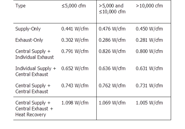
Source: California Energy Commission
Central IAQ standard design fan efficacy equals proposed or the limit from Table 39 whichever is lower
Additionally, for multifamily dwelling units, if the proposed system type is balanced, supply-only, or HRV/ERV, and the system maintenance components (supply air filters, outside air inlets, and heat/energy recovery cores) are not accessible, then the standard design fan efficacy equals proposed or the value from Table 38: Individual IAQ System Standard Design Fan whichever is lower. For non-accessible proposed systems with heat recovery the standard design is equal to the Proposed or 0.6 W/cfm whichever is lower
Heat/Energy Recovery
Heat/Energy recovery can be specified using recovery effectiveness or adjusted sensible recovery efficiency (ASRE) and sensible recovery efficiency (SRE). For larger AHRI rated equipment, inputs are covered in Section 5.7.7 Heat Recovery
Proposed Design
Systems serving individual dwelling units with supply ducts (balanced and supply-only) are simulated with reduced recovery efficiency (SRE and ASRE or recovery effectiveness) to account for maintenance and installation factors affecting system efficacy. For these systems, recovery efficiency is reduced by a factor of 0.90 (10 percent decrease in recovery efficiency). For IAQ systems with an FID meeting the specifications in Section 6.9.6.10 these factors don’t apply.
Standard Design
If the proposed design is a balanced central system, both central supply and central exhaust systems serving multiple dwelling units, in Climate Zones 1, 2, or 11-16, in a building with four or more habitable stories, the standard design is a heat recovery ventilation system with a sensible recovery effectiveness of 67% in both heating and cooling modes and includes recovery bypass to directly economize with ventilation air based on the outdoor air temperature limits specified in Table 170.2-G.
If the proposed design is a balanced system serving individual dwelling units in Climate Zones 1, 2, and 11-16, the standard design is a heat recovery ventilation system with a sensible recovery effectiveness of 67% in both heating and cooling modes.
For systems serving individual dwelling units, if the system does not meet the requirements in Section 6.8.6.11 IAQ System Component Accessibility, the standard design effectiveness matches the proposed or 67% whichever is higher.
Exhaust Air Sensible Heat Recovery Effectiveness
The effectiveness of an air-to-air heat exchanger between the building exhaust and entering outside air streams is defined as:
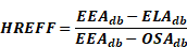
Where:
•HREFF - The air-to-air heat exchanger effectiveness
•EEAdb - The exhaust air humidity ratio (fraction of mass of moisture in air to mass of dry air) entering the heat exchanger
•ELAdb - The exhaust air humidity ratio leaving the heat exchanger
•OSAdb- The outside air humidity ratio
This results in two unitless numbers (ratio between 0 and 1), separate for cooling and heating, and is based on the proposed design.
Exhaust Air Sensible Part-Load Effectiveness
The effectiveness of an air-to-air heat exchanger between the building exhaust and entering outside air streams at 75 percent of design airflow is defined as:
Where:
•HREFF - The air-to-air heat exchanger effectiveness
•EEAdb - The exhaust air humidity ratio (fraction of mass of moisture in air to mass of dry air) entering the heat exchanger
•ELAdb - The exhaust air humidity ratio leaving the heat exchanger
•OSAdb- The outside air humidity ratio
This results in two unitless numbers (ratio between 0 and 1), separate for cooling and heating, and is based on the proposed design.
Economizer Enabled during Heat Recovery
All systems with airside heat recovery must identify if the economizer is enabled during heat recovery.
Proposed Design
Indication of whether the economizer is enabled when heat recovery is active is based on the proposed design.
Standard Design
The economizer is disabled if using balance system serving multiple dwelling units in Climate Zones 1, 2, and 11-16. Not applicable for Climate Zones 3-10.
For existing buildings, the economizer is disabled if using balance system serving multiple dwelling units in Climate Zones 1, 2, and 11-16. Not applicable for Climate Zones 3-10.
Recovery Type
Systems with airside heat recovery not using ASRE and SRE must identify the heat recovery system type. The type of heat recovery system is identified as sensible, latent, or total (sensible and latent).
Tempering Coils
Proposed Design
The proposed design may have tempering coils.
Standard Design
The standard design does not include tempering coils.
IAQ System Fault Indicator Display
All individual IAQ systems with a supply fan must specify if the system includes an FID that meets the following requirements.
IAQ System Fault Indicator Display Requirements
1. Fault indication responding to the following categories:
a. Filter check or maintenance, either based on performance or a predetermined schedule.
b. Low supply airflow.
c. Low exhaust airflow.
d. Sensor failure for sensors that assist in monitoring or controlling for the following operations, where such operations are provided: airflow regulation, frost control, supply air tempering, and economizing.
2. Fault indication using one or more of the following means:
a. A visual display that is readily accessible to occupants of the dwelling unit and located on or within one foot of the IAQ system control.
b. An electronic application.
c. An audible alarm accompanied by a visual display.
3. Instrumentation and reporting of the following:
a. Airflow.
b. Fan power.
4. FID certified to CEC by the manufacturer as meeting the above requirements.
Proposed Design
Selection is based on the proposed design.
Standard Design
The standard design assumes an FID system meeting the above requirements.
IAQ System Component Accessibility
All individual IAQ systems with a supply fan must specify if the system meets the following accessibility requirements.
Table 40: Multifamily IAQ System Component Accessibility Criteria
|
Dwelling Unit Ventilation System Component |
Location |
Accessible Determination |
|
Outdoor Air Intake |
All locations |
Intakes louvers, grilles, or screens shall be >3/8 inches except where prohibited by local jurisdictions or other code requirements. |
|
Outdoor Air Intake |
Exterior wall, soffit, or gable end |
All are considered accessible. |
|
Outdoor Air Intake |
Roof |
Access shall be provided in accordance with California Mechanical Code Section 304.3.1 requirements for appliances. |
|
Filters and Heat Exchangers |
Serviceable from conditioned space, unconditioned basements, balconies, accessible rooftops, or mechanical closets. Heat exchangers may also be serviceable from unconditioned attics if the IAQ system meets the FID requirements in Section 6.9.6.10. |
The H/ERV or supply ventilation system access panel shall be located within 10 feet of the walking surface. |
|
Filters and Heat Exchangers |
Roof |
Access shall be provided in accordance with California Mechanical Code Section 304.31 requirements for appliances. |
Source: California Energy Commission
Proposed Design
Selection is based on proposed design.
Standard Design
The standard assumes an IAQ system meeting the above requirements.