The following are characteristics of most zonally controlled systems that utilize dampers. Not all of these items need to be apparent for the system to be considered zonally controlled. Final determination may require consulting with the installer, designer and system manufacturer.
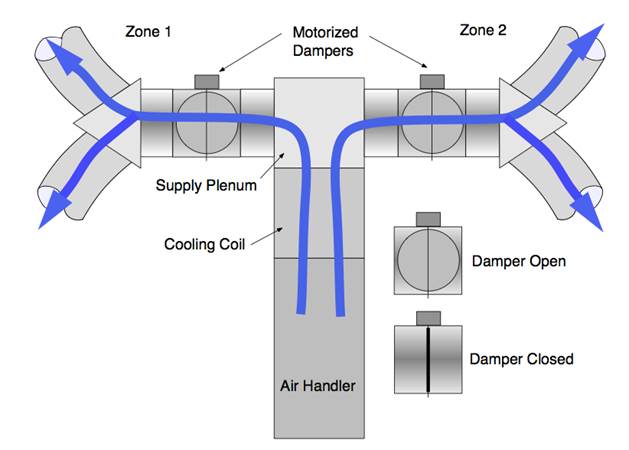
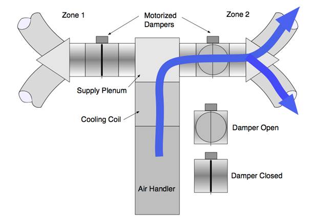
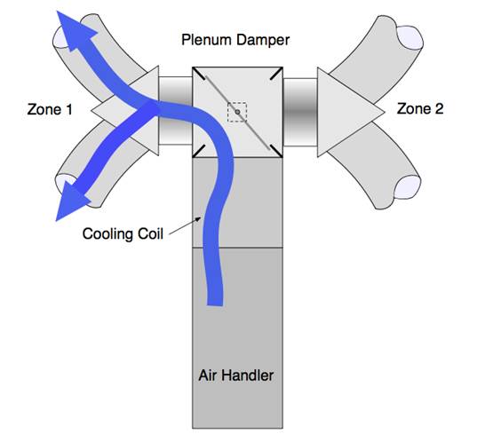
1. Motorized or actuated zone dampers on the supply ducts. These can be one or more large dampers in or near the supply plenum or they can be one damper for each supply outlet (register). See Figures 1 through 5.
2. Multiple thermostats or temperature sensors in area served by a single system. The most common two zone systems utilize ordinary thermostats for each zone. Some systems have a single master thermostat with small temperature sensors in each zone.
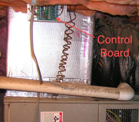
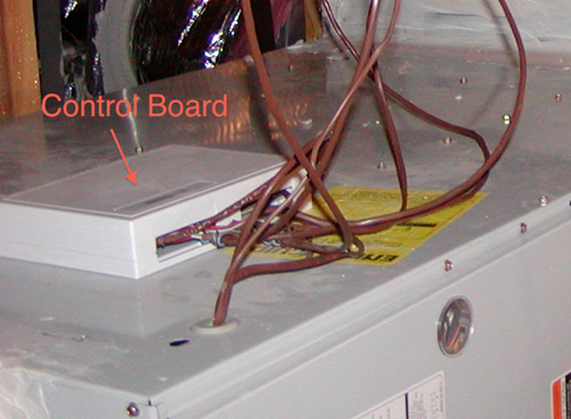
3. A control board on or near the air handler with low voltage wires going to the thermostats/temperature sensors and to each damper. Low voltage wires will also connect the control board and the main air handler control board. See photos below.
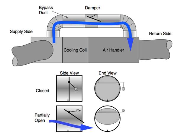
4. Bypass duct and damper. This will be a duct connecting the supply end directly to the return end. On the supply side it will connect after the coil and before the zone damper(s), usually off of the supply plenum. On the return side, it can either connect directly to the side of the return end of the furnace, near the return end of the furnace in a return plenum, or as far away as a return grill boot. An automatic damper will control airflow through this duct. When all zones are calling for cooling (all zone dampers open), the bypass damper should be fully closed. When one or more zone dampers close, the damper should open partially or fully as needed to reduce the supply plenum pressure. This is commonly achieved by a barometric bypass damper. Barometric dampers are held closed by an adjustable weight. When enough pressure builds up on one side of the damper, it overpowers the weight and opens the damper. See Figure 5. Another strategy is to use a motorized damper.
Figure 1: Illustration of a two-zone, two-damper duct system with both zones open to supply conditioned air.

Credit: Russ King, P.E.
Figure 2: Illustration of a two-zone, two-damper duct system with Zone 2 open to supply conditioned air. The Zone 1 Damper is closed.
 Credit: Russ King, P.E.
Figure 3: Illustration of a two-zone, single-damper duct system with both zones open to supply conditioned air.
Figure 4: Illustration of a two-zone, single-damper duct system with the damper positioned to supply conditioned air to Zone 1.
 Credit: Russ King, P.E.
Figure 5: Illustration of a system with a bypass duct and barometric-type bypass damper.
Credit: Russ King, P.E.
This diagram shows a common bypass duct/damper strategy. The bypass duct is sheet metal (which should always be insulated) and the damper is a barometric type. The details show how the damper opens when air pressure builds up against the adjustable weight. Sending heated or cooled air back into the space conditioning equipment can cause problems and reduce efficiency.
These photos show two examples of zonal control control-boards:
Figure 6: Photo of a duct-mounted control board.
Credit: Russ King, P.E.
Figure 7: Photo of a cabinet-mounted control board.
Credit: Russ King, P.E.