In the climates of California, laboratories have average annual energy intensities 10 to 20 times larger than offices when normalized by building area. The energy use of laboratories is driven from long hours of operation and the large quantities of outside air. Many lab buildings also have large internal loads.
Research in the climates of California showed annual cost of lab air at ~$3 to $5 per cfm/yr or $5 to $10/ft2/yr. At these costs the paybacks on retrofitting constant volume labs to variable air volume have been less than 10 years. With new construction the paybacks are much shorter.
The energy and demand savings are strongly dependant on the facility's characteristics including the following:
•The ratio of lab to non-lab space.
•The minimum airflow required by code or the facility EH&S department. These range from 4 air-changes per hour (ACH) to 18 ACH or higher.
•The climate.
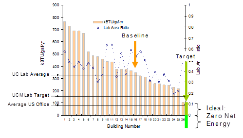
Figure 10-38 below shows benchmarking data from Labs 21 for lab buildings in the San Francisco Bay area. The total energy use intensity in kBtu/gsf/yr is shown on the left access. The 26 labs are arranged from highest to lowest normalized energy use. The right access is the "Lab Area Ratio" the ratio of lab area to total building area. There are three reference lines on this graph: the University of California campus wide average laboratory building end use intensity; the University of California Merced campus goal for their laboratories; and the average national energy end use for office buildings.
Using the criteria for cost effectiveness in the Standard and very conservative estimates of the first costs (using costs from VAV retrofits not new construction) this measure was shown to be cost effective in all California Climate Zones up to 14 ACH of minimum ventilation
Using off the shelf variable air volume controls can greatly reduce the energy use in laboratory buildings. New to the 2013 Standard, Title 24 requires VAV controls on all zones not required to be constant volume by the AHJ, facility EH&S department or other applicable health and safety code. Furthermore recent changes in ANSI/AIHA Z9.5 and NFPA 45 would allow lower minimum airflows in many hoods which would further increase the savings from variable air volume design.
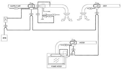
Figure 10-39 below show the zone components for a variable air volume (VAV) laboratory. There are three zone valves shown in this image: one each on the supply air to the zone; the fume hood (if one exists), and; the general exhaust valve (GEX) if one is needed. These zone valves can be venturi type valves as shown in this image or standard dampers like those used for VAV boxes in offices. The dampers or venturi valves must be designed to resist corrosion and damage from the exhaust. The hood valve when it is used is controlled to automatically maintain the design sash face velocity as the hood sash is opened or closed. The role of the supply valve is to maintain space pressurization by tracking the sum of the hood and general exhausts in the space. The supply valves are typically provided with a reheat coils to maintain space comfort for heating. The GEX is typically used to control the cooling, on call for cooling it opens, and the supply valve in turn opens to maintain space pressure. In some systems the supply modulates like a typical VAV box in response to the thermostat and the GEX modulates to maintain space pressure.
All three valves are made to control as either variable volume or constant volume depending on the application. A hood might for instance be required to be constant volume for dilution. If this is the case, a constant volume bypass hood should be employed. Even with a constant volume hood you will need a pressure independent hood valve if the exhaust it is attached to includes any variable volume zones. The same is true for constant volume supply or general exhaust: if any zone on a supply or exhaust duct is variable volume, all zone ducts on it must have pressure independent controls.
The fume exhaust is generally blown out of a stack. The design of the stack and the velocity of the discharge is selected to disperse all contaminants so that they are sufficiently dilute by the time they are near any occupants. For contaminants like radio isotopes for which there is no acceptable level of dilution, the exhaust system typically has some form of filtration that captures the particles of concern. On general lab exhaust there is typically an inlet bypass damper on the exhaust fan that modulates to keep a constant volume of exhaust moving at the stacks. Using multiple stacks in parallel you can stage off stacks and fans to save more energy.
There are no mandatory measures specific to laboratory exhaust. The equipment efficiencies in §110.1 and §110.2 apply.
The standards §140.9(c) require that all laboratory exhaust with minimum circulation rates of 10 ACH or lower shall be designed for variable volume control on the supply, fume exhaust and general exhaust.
An exception is provided for laboratory exhaust systems where constant volume is required by code, the Authority Having Jurisdiction (AHJ), or the facility Environmental Health and Safety (EH&S) division (Exception 1 to §140.9(c)). Examples include: hoods using perchloric acid; hoods with radio isotopes; and exhaust systems conveying dust or vapors that need a minimum velocity for containment.
A second exception is provided for new zones added to an existing constant volume exhaust system (Exception 2 to §140.9(c)).
As noted in the previous section variable volume controls are not required if you are adding zones to an existing constant volume system.
NRCC-PRC-09-E for Laboratory Exhaust Systems Requirements
This Compliance Documentation includes the Prescriptive Measures installed in the building with system description including system tag number, capacity, and reference to plans.
Project Description
PROJECT NAME is the title of the project, as shown on the plans and known to the enforcement agency.
DATE PREPARED is the last revision date of the plans. If the plans are revised after this date, it may be necessary to re-submit the compliance documentation to reflect the altered design. Note that it is the enforcement agency’s discretion whether or not to require new compliance documentation.
Documentation Author’s Declaration Statement
The CERTIFICATE of COMPLIANCE – Computer Room Systems Requirements is signed by both the Documentation Author and the Principal Designer who is responsible for preparation of the plans of building. This latter person is also responsible for this compliance documentation, even if the actual work is delegated to a different person acting as Documentation Author. It is necessary that the compliance documentation be consistent with the plans.
DOCUMENTATION AUTHOR is the person who prepared the compliance forms and who signs the Declaration Statement. The person’s telephone number is given to facilitate response to any questions that arise. A Documentation Author may have additional certifications such as an Energy Analyst or a Certified Energy Plans Examiner certification number. Enter number in the EA# or CEPE# box.
Principal Designer’s Declaration Statement
The Declaration Statement is signed by the person responsible for preparation of the plans for the building. This principal designer is also responsible for this compliance form, even if the actual work is delegated to someone else (the Documentation Author as described above). It is necessary that the compliance documentation be consistent with the plans. The Business and Professions Code governs who is qualified to prepare plans and therefore to sign this statement. See Section 2.2.2 Permit Application for applicable text from the Business and Professions Code.