The system is made up of the heating system, cooling system (if any), distribution system details and fans. The building ventilation cooling and indoor air quality ventilation systems are also defined at the building level for single family dwellings or as part of the dwelling unit information in multi-family buildings (see also Section 2.4.9 and 2.4.10).
The heating subsystem describes the equipment that supplies heat to an HVAC System. Heating systems are categorized according to the types show in Table 2-6.
|
Recommended Descriptor |
Heating Equipment Reference |
|
CentralFurnace |
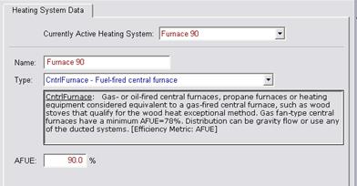
Gas- or oil-fired central furnaces, propane furnaces or heating equipment considered equivalent to a gas-fired central furnace, such as wood stoves that qualify for the wood heat exceptional method. Gas fan-type central furnaces have a minimum AFUE=78%. Distribution can be gravity flow or use any of the ducted systems. [Efficiency metric: AFUE] |
|
WallFurnGravity |
Non-central gas- or oil-fired wall furnace, gravity flow. Equipment has varying efficiency requirements by capacity. Distribution is ductless. [Efficiency metric: AFUE] |
|
WallFurnFan |
Non-central gas- or oil-fired wall furnace, fan-forced. Equipment has varying efficiency requirements by capacity. Distribution is ductless. [Efficiency metric: AFUE] |
|
FloorFurnace |
Non-central gas- or oil-fired floor furnace. Equipment has varying efficiency requirements by capacity. Distribution is ductless. [Efficiency metric: AFUE] |
|
RoomHeater |
Non-central gas- or oil-fired space heaters. Equipment has varying efficiency requirements. Distribution is ductless. [Efficiency metric: AFUE] |
|
Boiler |
Gas or oil boilers. Distribution systems can be Radiant, Baseboard or any of the ducted systems. Boiler may be specified for dedicated hydronic systems. Systems in which the boiler provides space heating and fires an indirect gas water heater (IndGas) may be listed as Boiler/CombHydro Boiler and is listed under “Equipment Type” in the HVAC Systems listing. [Efficiency metric: AFUE] |
|
SplitHeatPump |
Heating side of a split heat pump heating system that has one or more outdoor units supply heat to each habitable space in the dwelling unit. Heat is at least partly distributed using one of the ducted systems. [Efficiency metric: HSPF] |
|
DuctlessHeatPumpSystem |
One or more heat pump outdoor units that use refrigerant to transport heat to at least one terminal in each habitable space in the dwelling unit. These include small ductless mini-split and multiple-split heat pumps and packaged terminal (commonly called “through-the-wall”) units. Heat is not distributed using ducts either inside or outside of the conditioned space. [Efficiency metric: COP] |
|
RoomHeatPump |
Same as DuctlessHeatPumpSystem except that heat is not supplied to each habitable space in the dwelling unit. [Efficiency metric: COP] |
|
PkgHeatPump |
Heating side of central packaged heat pump systems. Central packaged heat pumps are heat pumps in which the blower, coils and compressor are contained in a single package, powered by single phase electric current, air cooled, rated below 65,000 Btuh. Distribution system is one of the ducted systems. [Efficiency metric: HSPF] |
|
LrgPkgHeatPump |
Heating side of large packaged units rated at or above 65,000 Btu/hr (heating mode). Distribution system is one of the ducted systems. These include water source and ground source heat pumps. [Efficiency metric: COP] |
|
Electric |
All electric heating systems other than space conditioning heat pumps. Included are electric resistance heaters, electric boilers and storage water heat pumps (air-water) (StoHP). Distribution system can be Radiant, Baseboard or any of the ducted systems. [Efficiency metric: HSPF] |
|
CombHydro |
Water heating system can be storage gas (StoGas, LgStoGas), storage electric (StoElec) or heat pump water heaters (StoHP). Distribution systems can be Radiant, Baseboard, or any of the ducted systems and can be used with any of the terminal units (FanCoil, RadiantFlr, Baseboard, and FanConv). |
Proposed Design
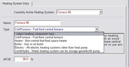
The user selects the type and supplies inputs for the heating subsystem in the heating system data screen shown in Figure 2-4 and Figure 2-5. The user inputs the appropriate rated heating efficiency factor. The rated heating capacity is not a compliance variable and is calculated for use in the simulation by the compliance software for all systems except heat pumps. For heat pumps the user inputs the rated heating capacity at 47°F and 17°F for the heat pump compressor to be installed and the software sizes the backup electric resistance heat for use in the simulation.
Systems rated with a Coefficient of Performance (COP) only must calculate the Heating Seasonal Performance Factor (HSPF) for use in performance compliance:
Equation 2-1 HSPF = (3.2 x COP) – 2.4
Until there is an approved compliance option for ductless heat pumps (mini-split, multi-split VRF systems) they are simulated as a split system equivalent to the standard design with default duct conditions.
Standard Design
When electricity is used for heating, the heating equipment for the standard design is an electric split system heat pump with a Heating Seasonal Performance Factor (HSPF) meeting the Appliance Efficiency Regulations requirements for split systems with default ducts in the attic. The standard design heat pump compressor size is determined by the software based on the compressor size calculated for the air conditioning system.
When electricity is not used for heating, the equipment used in the standard design building is a gas furnace (or propane if natural gas is not available) with default ducts in the attic and an Annual Fuel Utilization Efficiency (AFUE) meeting the Appliance Efficiency Regulations minimum efficiency for central systems. When a proposed design uses both electric and non-electric heat, the standard design is a gas furnace.
Verification and Reporting
The proposed heating system type and rated efficiency are reported in the compliance reports. The rated heating capacity of each proposed heat pump is reported on the CF1R so that installed size can be verified to be at least as large.

Combined hydronic space/water heating is a system whereby a water heater is used to provide both space heating and water heating. Dedicated hydronic space heating systems are also an optional capability. Space heating terminals may include fan coils, baseboards, and radiant surfaces (floors, walls or ceilings).
For combined hydronic systems, the water heating portion is modeled in the normal manner. For space heating, an effective AFUE is calculated for gas water heaters. For electric water heaters or heat pumps, an effective HSPF is calculated. The procedures for calculating the effective AFUE or HSPF are described below.
Combined hydronic space conditioning cannot be combined with zonal control credit.
Proposed Design
When a fan coil is used to distribute heat, the fan energy and the heat contribution of the fan motor must be considered. The algorithms for fans used in combined hydronic systems are the same as those used for gas furnaces and are described in Chapter 3.
If a large fan coil is used and air distribution ducts are located in the attic, crawlspace or other unconditioned space, the efficiency of the air distribution system must be determined using methods consistent with those described in Section 2.4.6 Duct efficiency is accounted for when the distribution type is ducted.
2.4.2.1 Large or Small Storage Gas Water Heater
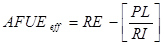
When storage gas water heaters are used in combined hydronic applications, the effective AFUE is given by the following equation:
Where:
AFUEeff = The effective AFUE of the gas water heater in satisfying the space heating load.
RE = The recovery efficiency (or thermal efficiency) of the gas water heater. A default value of 0.70 may be assumed if the recovery efficiency is unknown. This value is generally available from the Energy Commission appliance directory.
PL = Pipe losses (kBtu/h). This can be assumed to be zero when less than 10 feet of piping between the water heater storage tank and the fan coil or other heating elements are located in unconditioned space (see Equation
RI=The rated input of the gas water heater (kBtu/h) available from the Energy Commission’s appliance directory.
2.4.2.2 Storage Electric Water Heater
The HSPF of storage water heaters used for space heating in a combined hydronic system is given by the following equations.
Equation 2-3 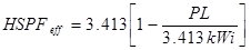
Where:
HSPFeff = The effective HSPF of the electric water heater in satisfying the space heating load.
PL=Pipe losses (kBtu/h). This can be assumed to be zero when less than 10 feet of piping between the water heater storage tank and the fan coil or other heating elements are located in unconditioned space (see Equation
RI=The kilowatts of input to the water heater available from the Energy Commission’s appliance directory.
2.4.2.3 Heat Pump Water Heater
The HSPF of heat pump water heaters used for space heating in a combined hydronic system is given by the following equations. If the system has a fan coil, the HSPFeff is used. HSPFw/o_fan is used if there is no fan coil.
Equation 2-4 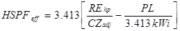
Where:
HSPFeff = The effective HSPF of the electric water heater in satisfying the space heating load.
CZadj =The climate zone adjustment (see Appendix E Table RE-3).
PL=Pipe losses (kBtu/h). This can be assumed to be zero when less than 10 feet of piping between the water heater storage tank and the fan coil or other heating elements are located in unconditioned space (see Equation
RI=The kilowatts of input to the water heater available from the Energy Commission’s appliance directory.
REhp = The recovery efficiency of the heat pump water heater. Equation 2-8 may be used as a default if the recovery efficiency is not known.
Equation 2-5 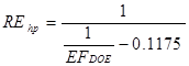
Where:
EFDOE = The energy factor of the heat pump water heater when tested according to the DOE test procedure.
Standard Design
When electricity is used for heating, the heating equipment for the standard design is an electric split system heat pump with a Heating Seasonal Performance Factor (HSPF) meeting the Appliance Efficiency Regulations requirements for split systems, unless the proposed design is a room heat pump, in which case the standard design is the same. The standard design heat pump compressor size is determined by the software based on the compressor size calculated for the air conditioning system.
When electricity is not used for heating, the equipment used in the standard design building is a gas furnace (or propane if natural gas is not available) with default ducts in the attic and an Annual Fuel Utilization Efficiency (AFUE) meeting the Appliance Efficiency Regulations minimum efficiency for central systems. When a proposed design uses both electric and non-electric heat, the standard design is a gas furnace.
When propane is used for a combined hydronic system, the water heater is electric.
Proposed Design
This listing is completed for hydronic systems that have more than 10 feet of piping (plan view) located in unconditioned space. As many rows as necessary may be used to describe the piping system.
Standard Design
The standard design is established for a hydronic system in the same way as for a central system, as described in Section 2.4.1.
Verification and Reporting
A hydronic or combined hydronic system is reported in the Special Features listing on the CF1R.
Other information reported includes:
•Piping Run Length (ft). The length (plan view) of distribution pipe located in unconditioned space, in feet, between the primary heating/cooling source and the point of distribution.
•Nominal Pipe Size (in.). The nominal (as opposed to true) pipe diameter in inches.
•Insulation Thickness (in.). The thickness of the insulation in inches. Enter "none" if the pipe is uninsulated.
•Insulation R-value (hr-ft2-°F/Btu). The installed R-value of the pipe insulation. Minimum pipe insulation for hydronic systems is as specified in §150.1(j).

Until there is an approved compliance option for ground source heat pump systems to accurately represent this system, which uses the earth as a source of energy for heating and as a heat sink for energy when cooling, a split system equivalent to the standard design with default duct conditions is substituted for the proposed system. The mandatory efficiencies for ground water source heat pumps are a minimum Coefficient of Performance (COP) for heating and EER for cooling.

The cooling subsystem describes the equipment that supplies cooling to an HVAC System.
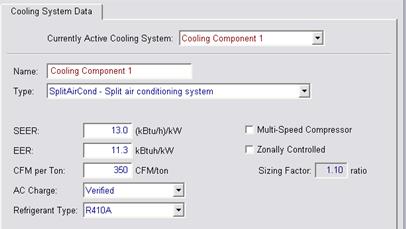
Proposed Design
The user selects the type of cooling equipment from Table 2-7 and enters basic information to model the energy use of the equipment. At a minimum, enter the cooling equipment descriptor, zoning type (Table 2-8), and SEER. The default is NotZonal. For ducted cooling systems the cooling air flow from the conditioned zone through the cooling coil is an input. The rated cooling capacity is not a compliance variable. See sections below for the details of specific inputs.
Standard Design
The cooling system for the standard design building is a non zonal control split system air conditioner or heat pump meeting the minimum requirements of §150.1(c) and Table 150.1-A. The standard design system shall assume verified refrigerant charge in climate zones 2 and 8 through 15 for all ducted split systems, ducted package systems, and mini-split systems. Mandatory fan efficacy is assumed in all climate zones.
Verification and Reporting
Information shown on the CF1R includes cooling equipment type, cooling efficiency (SEER and/or EER). Measures requiring verification are listed on the in the HERS Verification section of the CF1R.
2.4.5.1
Verified Refrigerant Charge or
Charge Indicator Display
Proper refrigerant charge is necessary for electrically driven compressor air conditioning systems to operate at full capacity and efficiency. Software calculations set the compressor efficiency multiplier to 0.90 to account for the impact of improper refrigerant charge or 0.96 for proper charge.
Proposed Design
The software allows the user to indicate if systems will have diagnostically tested refrigerant charge or a field verified charge indicator display (CID). This applies only to ducted split system and packaged air conditioners and heat pumps, as well as mini-split heat pumps.
Standard Design
The standard design building is modeled with either diagnostically tested refrigerant charge or a field verified charge indicator display if the building is in climate zone 2 or 8 through 15, and is required by §150.1(c) and Table 150.1-A for the proposed cooling system type.
Verification and Reporting
These features require field verification or diagnostic testing and are reported in the HERS Required Verification listings on the CF1R. Details on refrigerant charge measurement are discussed in Reference Appendices, Residential Appendix RA. Information on the requirements for charge indicator displays is located in Reference Appendices, Joint Appendix JA6.1.
|
Recommended Descriptor |
Cooling Equipment Reference |
|
NoCooling |
Entered when the proposed building is not cooled or when cooling is optional (to be installed at some future date). Both the standard design equivalent building and the proposed design use the same default system (refer to section 2.4.8.3). [Efficiency metric: SEER] |
|
SplitAirCond |
Split air conditioning systems. Distribution system is one of the ducted systems. [Efficiency metric: SEER and EER] |
|
PkgAirCond |
Central packaged air conditioning systems less than 65,000 Btuh cooling capacity. Distribution system is one of the ducted systems. [Efficiency metric: SEER and EER] |
|
LrgPkgAirCond |
Large packaged air conditioning systems rated at or above 65,000 Btu/hr (cooling capacity). Distribution system is one of the ducted systems. [Efficiency metric: EER] |
|
DuctlessSplitAirCondSystem |
One or more split air conditioning outdoor units that use refrigerant to transport cooling to at least one terminal in each habitable space in the dwelling unit. These include small ductless mini-split and multiple-split heat air conditioners and packaged terminal (commonly called “through-the-wall”) units. Cooling is not distributed using ducts either inside or outside of the conditioned space. [Efficiency metric: EER] |
|
RoomAirCond |
Same as DuctlessSplitAirCondSystem except that cooling is not supplied to each habitable space in the dwelling unit. [Efficiency metric: EER] |
|
SplitHeatPump |
Cooling side of split heat pump systems. Distribution system is one of the ducted systems. [Efficiency metric: SEER and EER<65,000 Btu/hr EER>65,000 Btu/hr] |
|
PkgHeatPump |
Cooling side of central single-packaged heat pump systems with a cooling capacity less than 65,000 Btuh. Distribution system is one of the ducted systems. [Efficiency metric: SEER] |
|
LrgPkgHeatPump |
Cooling side of large packaged heat pump systems rated at or above 65,000 Btu/hr (cooling capacity). Distribution system is one of the ducted systems. [Efficiency metric: EER] |
|
GasCooling |
Gas absorption cooling. Three descriptors, COP95 (the rated COP for the gas portion), CAP95 (the rated capacity), and PPC (the parasitic electric energy at rated conditions in Watts). |
|
DuctlessHeatPumpSystem |
One or more heat pump outdoor units that use refrigerant to transport cooling to at least one terminal in each habitable space in the dwelling unit. These include small ductless mini-split and multiple-split heat pumps and packaged terminal (commonly called “through-the-wall”) units. Cooling is not distributed using ducts either inside or outside of the conditioned space. [Efficiency metric: EER] |
|
RoomHeatPump |
Same as DuctlessHeatPumpSystem except that cooling is not supplied to each habitable space in the dwelling unit. [Efficiency metric: EER] |
|
EvapDirect |
Direct evaporative cooling systems. Assume minimal efficiency air conditioner. The default distribution system location is DuctAttic; evaporative cooler duct insulation requirements are the same as those for air conditioner ducts. [Efficiency metric: SEER] |
|
EvapIndirDirect |
Indirect-direct evaporative cooling systems. Assume energy efficiency ratio of 13 EER. Requires air flow and media saturation effectiveness from the CEC directory. |
|
EvapIndirect |
Indirect cooling systems. The default distribution system location is DuctAttic; evaporative cooler duct insulation requirements are the same as those for air conditioner ducts. Assume energy efficiency ratio of 13 EER. Requires air flow and media saturation effectiveness from the CEC directory. |
|
Evap/CC |
Evaporatively Cooled Condensers. A split mechanical system, with a water-cooled condenser coil. (Efficiency metric: EER) |
|
Zoning Type |
Description |
|
ZonalSingleSpeed |
A ducted cooling system with a single speed compressor and zone control dampers |
|
ZonalMultiSpeed |
A ducted cooling system with a multiple speed or variable speed compressor and zone control dampers |
|
ZonalSingleSpeedBypass |
A zonally controlled HVAC system with a bypass duct |
|
ZonalSingleSpeedNoBypass |
A zonally controlled HVAC system with no bypass duct |
|
NotZonal |
Any cooling system that has no zone control dampers |
|
Measure |
Description |
Procedures (Need Update) |
|
Verified Refrigerant Charge |
Air-cooled air conditioners and air-source heat pumps be diagnostically tested to verify that the system has the correct refrigerant charge. The system must also meet the system airflow requirement. |
|
|
Verified Charge Indicator Display |
A Charge Indicator Display can be installed as an alternative to refrigerant charge testing. |
|
|
Verified System Airflow |
When compliance requires verified System Airflow greater than or equal to a specified criterion. |
|
|
Verified Air-handling Unit Fan Efficacy |
To verify that Fan Efficacy (Watt/cfm) is less than or equal to a specified criterion. |
|
|
Verified EER |
Credit for increased EER by installation of specific air conditioner or heat pump models. |
|
|
Verified SEER |
Credit for increased SEER. |
|
|
Evaporatively Cooled Condensers |
Must be combined with duct leakage testing, refrigerant charge, and verified EER. |
2.4.5.2
Verified System
Airflow
Adequate airflow from the conditioned space is required to allow ducted air conditioning systems to operate at their full efficiency and capacity. Efficiency is achieved by the air distribution system design, by improving the efficiency of motors or air distribution systems with less resistance to airflow. Software calculations account for the impact of airflow on sensible heat ratio and compressor efficiency.
Proposed Design
The default cooling airflow is 150 cfm/ton for ZonalSingleSpeed systems and 350 cfm/ton for all other ducted cooling systems. Users may model a higher airflow and receive credit in the compliance calculation if greater verified system airflow is diagnostically tested using the procedures of Reference Appendices, Residential Appendix RA3.
If no cooling system is installed, this value is assumed to be 16.8 cfm/1000 Btu furnace nominal output specified by the manufacturer.
Standard Design
The standard design shall assume a system that complies with mandatory and prescriptive requirements for the applicable climate zone.
Verification and Reporting
The airflow rate verification compliance target (cfm or cfm/ton) is reported in the HERS Required Verification listings of the CF1R.
When there is no cooling system it is reported on the CF1R as a special feature.
2.4.5.3
Verified Air Handling Unit Fan
Efficacy
The mandatory requirement in §150.0(m)13 is for an air-handling unit fan efficacy less than or equal to 0.58 Watts/cfm as verified by a HERS rater. The alternative to HERS verification of 0.58 Watts/cfm is HERS verification of a return duct design that conforms to the specification given in Table 150.0-C or D. However, if a value less than 0.58 Watts/cfm is modeled by the software user for compliance credit, the system fan efficacy value modeled by the user shall be verified by a HERS Rater, and the alternative return duct design method using Table 150.0(m)13 is not allowed for use in demonstrating compliance.
Proposed Design
The software shall allow the user to enter the fan efficacy. The default mandatory value is 0.58 W/cfm. However, users may specify a lower value and receive credit in the compliance calculation if verified and diagnostically tested using the procedures of Reference Appendices, Residential Appendix RA3.3
If no cooling system is installed, this value is assumed to be 0.58 W/cfm.
Standard Design
The standard design shall assume a verified fan efficacy complying with the mandatory requirement for less than or equal to 0.58 Watts/cfm.
Verification and Reporting
For user inputs lower than the default mandatory 0.58 Watts/cfm, fan efficacy is reported in the HERS Required Verification listings of the CF1R.
For default mandatory 0.58 Watts/cfm, the choice of either Fan Efficacy or Alternative Return duct design according to Table 150.0-C,D is reported in the HERS Required Verification listings of the CF1R.
When there is no cooling system it is reported on the CF1R as a special feature.
2.4.5.4
Verified Energy Efficiency Ratio
(EER)
Proposed Design
Software shall allow the user the option to enter an EER rating for central cooling equipment in “compliance 2014” mode (a HERS verified measure). For equipment that is rated only with an EER (some evaporative coolers, room air conditioners), the user will enter the EER as an SEER. For “compliance 2015,” the Appliance Efficiency Regulations require a minimum SEER and EER for central cooling equipment. When using compliance 2015, only if a value higher than 11.7 EER is shown for central cooling equipment, is it reported as a HERS verified measure.
Standard Design
The standard design for 2014 does not include an EER rating for cooling equipment. For compliance 2015, the standard design for central air conditioning equipment is 11.7 EER.
Verification and Reporting
Verified EER is reported in the HERS Required Verification listings on the CF1R for 2014 compliance. For 2015, EER verification is only required if higher than 11.7 EER is modeled. The EER rating is verified using rating data from AHRI Directory of Certified Product Performance at www.ahridirectory.org or another directory of certified product performance ratings approved by the Commission for determining compliance.
2.4.5.5
Verified Seasonal Energy
Efficiency Ratio (SEER)
Proposed Design
The software allows the user to specify the SEER value.
Standard Design
The standard design is based on the default minimum efficiency SEER for the type of cooling equipment modeled in the proposed design, based on the applicable Appliance Efficiency Regulations. For central cooling equipment, the minimum efficiency becomes 14 SEER and 11.7 EER in 2015.
Verification and Reporting
If a SEER higher than the default minimum efficiency is modeled in software, the SEER requires field verification. The higher than minimum SEER rating is verified using rating data from AHRI Directory of Certified Product Performance at www.ahridirectory.org or another directory of certified product performance ratings approved by the Commission for determining compliance. Verified SEER is reported in the HERS Required Verification listings on the CF1R.
2.4.5.6
Verified Evaporatively-Cooled
Condensers
Proposed Design
Software shall allow users to specify an evaporatively-cooled condensing unit. The installation must comply with the requirements of RA4.3.2 to ensure the predicted energy savings are achieved. This credit must be combined with verified refrigerant charge testing, EER, and duct leakage testing.
Standard Design
The standard design is based on a split system air conditioner meeting the requirements of §150.1(c) and Table 150.1-A.
Verification and Reporting
An evaporatively-cooled condensing unit, verified EER, and duct leakage testing are reported in the HERS Required Verification listings on the CF1R.
2.4.5.7
Evaporative Cooling
Evaporative cooling technology is best suited for dry climates where direct and/or indirect cooling of the supply air stream can occur without compromising indoor comfort. Direct evaporative coolers are the most common system types currently available, but provide less comfort and deliver more moisture to the indoor space. They are assumed to be equivalent to a minimum split system air conditioner. The evaporative cooling modeling methodology addresses two performance issues. The first performance issue is rising indoor relative humidity during periods with extended cooler operation. Since modeling of indoor air moisture levels is beyond the capability of simulation models, a simplified algorithm is used to prohibit evaporative cooler operation during load hours when operation is expected to contribute to uncomfortable indoor conditions. The algorithm disallows cooler operation when outdoor wet bulb temperatures are 70°F, or above. The second performance issue relates to evaporative cooler capacity limitations. Since evaporative coolers are 100 percent outdoor air systems, their capacity is limited by the outdoor wet bulb temperature. Each hour with calculated cooling load, the algorithm will verify that the cooling capacity is greater than the calculated house cooling load.
Proposed Design
Software shall allow users to specify one of three types of evaporative cooling: (1) direct evaporative cooler is the most commonly available system type, (2) indirect, or (3) indirect-direct. Product specifications and other modeling details are found in the Energy Commission appliance directory for evaporative cooling. Direct system types are assigned an efficiency of 13 SEER (or minimum appliance efficiency standard for split system cooling). The default system type is evaporative direct. For indirect or indirect-direct, select the appropriate type, from the Energy Commission appliance directory and input a 13 EER as well as the air flow and media saturation effectiveness or cooling effectiveness from the Energy Commission appliance directory.
Standard Design
The standard design is based on a split system air conditioner meeting the requirements of §150.1(c) and Table 150.1-A.
Verification and Reporting
When a direct evaporative cooling system is modeled, the system type and minimum efficiency are shown in the appropriate section of the CF1R. When indirect or indirect-direct evaporative cooling is modeled, the EER verification is shown in the HERS verification section of the CF1R along with the system type, air flow and system effectiveness.
If multiple HVAC distribution systems serve a building each system and the conditioned space it serves may be modeled in detail separately or the systems may be aggregated together and modeled as one large system. If the systems are aggregated together they must be the same type and all meet the same minimum specifications.
For the purposes of duct efficiency calculations, the supply duct begins at the exit from the furnace or air handler cabinet.
2.4.6.1 Distribution Type
Proposed Design
The compliance software shall allow the user to select from the basic types of HVAC distribution systems and locations 'listed in Table 2-10. For ducted systems, the default location of the HVAC ducts and the air handler are in conditioned space for multi-family buildings and in the attic for all other buildings.
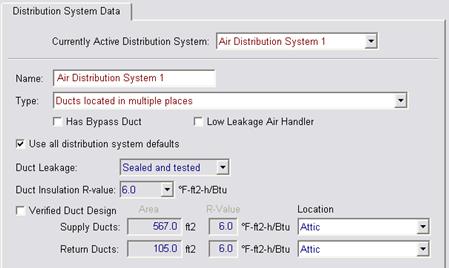
The software will allow users to select default assumptions or specify any of the verified or diagnostically tested HVAC distribution system conditions in the proposed design (see Figure 2-7 and Table 2-11), including duct leakage target, R-value, supply and return duct area, diameter and location.
|
Recommended Descriptors |
HVAC Distribution Type and Location Reference |
|
Air Distribution Systems |
Fan-powered, ducted distribution systems that can be used with most heating or cooling systems. When ducted systems are used with furnaces, boilers, or combined hydronic/water heating systems the electricity used by the fan is calculated. R-value is specified in "Duct R-value" column when a ducted system is specified |
|
Ducts located in unconditioned attic |
Ducts located overhead in the unconditioned attic space. |
|
Ducts located in a crawl space |
Ducts located under floor in the crawl space. |
|
Ducts located in a garage |
Ducts located in an unconditioned garage space. |
|
Ducts located within the conditioned space (except < 12 lineal ft) |
Ducts located within the conditioned floor space except for less than 12 linear feet of duct, furnace cabinet and plenums, typically an HVAC unit in the garage mounted on return box with all other ducts in conditioned space. |
|
Ducts located entirely in conditioned space |
HVAC unit or systems with all HVAC ducts (supply and return) located within the conditioned floor space. Location of ducts in conditioned space eliminates conduction losses but does not change losses due to leakage. Leakage from either ducts that are not tested for leakage or from sealed ducts is modeled as leakage to outside the conditioned space. |
|
Distribution system without ducts |
Air distribution systems without ducts such as ductless split system air conditioners and heat pumps, window air conditioners, through-the-wall heat pumps, wall furnaces, floor furnaces, radiant electric panels, combined hydronic heating equipment, electric baseboards or hydronic baseboard finned-tube natural convection systems, etc. |
|
Ducts located in outdoor locations |
Ducts located in exposed locations outdoors. |
|
Verified low leakage ducts located entirely in conditioned space |
Duct systems for which air leakage to outside is equal to or less than 25 cfm when measured in accordance with Reference Appendices, Residential Appendix RA3.1. |
|
Ducts located in multiple places |
Ducts with different supply and return duct locations. |
|
Measure |
Description |
Procedures |
|
Verified Duct Sealing |
Mandatory measures require that space conditioning ducts be sealed. Field verification and diagnostic testing is required to verify that approved duct system materials are utilized and that duct leakage meets the specified criteria. |
|
|
Verified Duct Location, Reduced Surface Area and R-value |
Compliance credit can be taken for improved supply duct location, reduced surface area and R-value. Field verification is required to verify that the duct system was installed according to the duct design, including location, size and length of ducts, duct insulation R-value and installation of buried ducts.1 For buried ducts measures Verified Insulation Construction Quality (QII) is required as well as duct sealing. |
|
|
Low Leakage Ducts in Conditioned Space |
When the Standards specify use of the procedures in Section RA3.1.4.3.8 to determine if space conditioning system ducts are located entirely in directly conditioned space, the duct system location is verified by diagnostic testing. Compliance credit can be taken for verified duct systems with low air leakage to the outside when measured in accordance with Reference Appendices, Residential Appendix Section RA3.1.4.3.8. Field Verification for ducts in conditioned space is required. Duct sealing is required. |
|
|
Low Leakage Air-handling Units |
Compliance credit can be taken for installation of a factory sealed air handling unit tested by the manufacturer and certified to the Commission to have met the requirements for a Low Leakage Air-Handling Unit achieved. Field verification of the air handler’s model number is required. Duct Sealing is required. |
|
|
Verified Return Duct Design |
Verification to confirm that the return duct design conforms to the criteria given in Table 150.0-C or Table 150.0-D. as an alternative to meeting 0.58 W/cfm fan efficacy of §150.0(m)0. |
|
|
Verified Air Filter Device Design |
Verification to confirm that the air filter devices conform to the requirements given in §150.0(m)12. |
|
|
Verified Bypass Duct Condition |
Verification to determine if system is zonally controlled, and confirm that bypass ducts condition modeled matches installation. |
|
|
1. Compliance credit for increased duct insulation R-value (not buried ducts) may be taken without field verification if the R-value is the same throughout the building, and for supply ducts located in crawl spaces and garages where all supply registers are either in the floor or within 2 feet of the floor. These two credits may be taken subject only to enforcement agency inspection. | ||
Standard Design
The standard heating and cooling system for central systems is modeled with non-designed air distribution ducts located as described in Table 2-12, with verified tested duct leakage (see Table 2-15). The standard design duct insulation is determined by Package A as R-6 in climate zones 1-10, 12-13, and R-8 in climate zones 11 and 14-16. The standard design building is assumed to have the same number of stories as the proposed design for purposes of determining the duct efficiency.
|
Configuration of the |
Standard Design | |
|
Standard Design Duct Location |
Detailed Specifications | |
|
Attic over the dwelling unit |
Ducts and air handler located in the attic |
Ducts sealed (mandatory
requirement) No credit for verified R-value, location or duct design |
|
No attic but crawl space or basement |
Ducts and air handler located in the crawl space or basement | |
|
Multi-family buildings and buildings with no attic, crawl space or basement |
Ducts and air handler located indoors | |
This table is applicable only when the standard design system has air distribution ducts as determined in Table 2-10.
Verification and Reporting
Distribution type, location, R-value, and whether tested and sealed will be shown on the CF1R. If there are no ducts, this is shown as a special feature on the CF1R. Any duct location other than attic (e.g., crawl space) is shown as a special feature on the CF1R. Ducts in crawl space or basement shall include a special feature note if supply registers are located within 2 feet of the floor. Measures that require HERS verification will be shown in the HERS Verification section of the CF1R.
2.4.6.2
Duct
Location
Duct location determines the external temperature for duct conduction losses, the temperature for return leaks, and the thermal regain of duct losses.
Proposed Design
If any part of the supply or return duct system is located in an unconditioned attic, that entire duct system is modeled with an attic location. If no part of the supply or return duct system is located in the attic, but the duct system is not entirely in conditioned space, it is modeled in the unconditioned zone which contains the largest fraction of its surface area. If the supply or return duct system is located entirely in conditioned space or the building type is multifamily, the duct system is modeled in conditioned space.
For ducted HVAC systems with some or all ducts in unconditioned space, the user specifies the R-value and surface area of supply and return ducts, and the duct location.
Duct location and areas other than the defaults shown in Table 2-13 may be used following the verification procedures in Reference Appendices, Residential Appendix RA3.1.4.1.
Standard Design
The standard design duct location is determined from the building conditions (see Table 2-12).
Verification and Reporting
Duct location is reported on the CF1R. Ducts in conditioned space in other than multi-family buildings or low leakage ducts in conditioned space are reported in the HERS Required Verification listing on the CF1R.
Default duct locations are as shown in Table 2-13. The duct surface area for crawl space and basement applies only to buildings or zones with all ducts installed in the crawl space or basement. If the duct is installed in locations other than crawl space or basement, the default duct location is “Other.” For houses with 2 or more stories 35 percent of the default duct area may be assumed to be in conditioned space as shown in Table 2-13.
The surface area of ducts located in conditioned space is ignored in calculating conduction losses.
|
Supply duct location |
Location of Default Duct Surface Area | |
|
One story |
Two or more story | |
|
All in Crawl space |
100% crawl space |
65% crawl space 35% conditioned space |
|
All in Basement |
100% Basement |
65% basement 35% conditioned space |
|
Other |
100% attic |
65% attic 35% conditioned space |
2.4.6.3
Duct Surface Area
The supply-side and return-side duct surface areas are treated separately in distribution efficiency calculations. The duct surface area is determined using the following methods.
2.4.6.4 Default Return Duct Surface Area
Default return duct surface area is calculated using:
Where Kr (return duct surface area coefficient) is 0.05 for one-story buildings and 0.1 for two or more stories.
2.4.6.5 Default Supply Duct Surface Area
Standard Design
The standard design and default proposed design supply duct surface area is calculated using Equation 2-7.
Where Ks (supply duct surface area coefficient) is 1 for one-story buildings and 0.65 for two or more stories.
2.4.6.6 Supply Duct Surface Area for Less Than 12 feet of Duct In Unconditioned Space
Proposed Design
For proposed design HVAC systems with air handlers located outside the conditioned space but with less than 12 linear feet of duct located outside the conditioned space including air handler and plenum, the supply duct surface area outside the conditioned space is calculated using Equation 2-8. The return duct area remains the default for this case.
2.4.6.7
Diagnostic Duct Surface Area
Proposed designs may claim credit for reduced surface area using the procedures in Reference Appendices, Residential Appendix RA3.1.4.1.
The surface area of each duct system segment is calculated based on its inside dimensions and length. The total supply surface area in each unconditioned location (attic, attic with radiant barrier, crawl space, basement, other) is the sum of the area of all duct segments in that location. The surface area of ducts completely inside conditioned space need not be input in the compliance software and is not included in the calculation of duct system efficiency. The area of ducts in floor cavities or vertical chases that are surrounded by conditioned space and separated from unconditioned space with draft stops are also not included.
2.4.6.8
Bypass
Duct
Proposed Design
Software shall allow users to specify whether a bypass duct is or is not used for a zonally controlled forced air system.
Standard Design
The standard design is based on a split system air conditioner meeting the requirements of §150.1(c) and Table 150.1-A. The system is not a zonally-controlled system.
Verification and Reporting
An HVAC system with zonal control, and whether the system is assumed to have a bypass duct or have no bypass duct, is reported in the HERS Required Verification listings on the CF1R.
2.4.6.9
Duct System
Insulation
For the purposes of conduction calculations in both the standard and proposed designs, 85 percent of the supply and return duct surface is assumed to be duct material at its specified R-value and 15 percent is assumed to be air handler, plenum, connectors and other components at the mandatory minimum R-value.
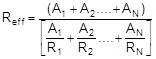
The area weighted effective R-value is calculated by the compliance software using Equation 2-9 and including each segment of the duct system that has a different R-value.
Where:
Reff = Area weighted effective R-value of duct
system for use in calculating duct efficiency,
(h-ft²-°F/Btu)
AN = Area of duct segment n, square feet
Rn = R-value of duct segment n including film
resistance, (duct insulation rated R + 0.7),
(h-ft²-°F/Btu)
The software user inputs the R-value of the proposed duct insulation. The default duct thermal resistance is R-6.0.
Package A required duct insulation R-values are used in the standard design.
Verification and Reporting
Duct location, duct R-value, non-standard supply and return duct areas are reported on the CF1R. Credit for systems with mixed insulation levels or ducts buried in the attic require the compliance and diagnostic procedures in Reference Appendices, Residential Appendix RA3.1.4.1.
2.4.6.10 Buried Attic Ducts
Ducts partly or completely buried in blown attic insulation in dwelling units meeting the requirements for verified quality insulation installation may take credit for increased effective duct insulation.
The duct design shall identify the segments of the duct that meet the requirements for being buried, and these are separately input into the computer software. Ducts to be buried shall have a minimum of R-6.0 duct insulation prior to being buried. The user shall calculate the correct R-value based on the modeled attic insulation R-value, insulation type, and duct size for ducts installed on the ceiling, and whether the installation meets the requirements for deeply buried ducts for duct segments buried in lowered areas of ceiling.
The portion of duct runs directly on or within 3.5 inches of the ceiling gypsum board and surrounded with blown attic insulation of R-30 or greater may take credit for increased effective duct insulation as shown in Table 2-14. Credit is allowed for buried ducts on the ceiling only in areas where the ceiling is level and there is at least 6 inches of space between the outer jacket of the installed duct and the roof sheathing above.
Duct segments deeply buried in lowered areas of ceiling and covered by at least 3.5 inches of insulation above the top of the duct insulation jacket may claim effective insulation of R-25 for fiberglass insulation and R-31 for cellulose insulation.
Proposed Design
The software shall allow the user to specify the effective R-value of buried ducts. This feature must be combined with duct sealing and verified quality insulation installation. The default is no buried ducts.
Standard Design
The standard design has no buried ducts
Verification and Reporting
Buried duct credit is reported in the HERS Required Verification listing on the CF1R.
|
|
Nominal Round Duct Diameter | ||||||||
|
Attic Insulation |
4'' |
5'' |
6'' |
7'' |
8'' |
10'' |
12'' |
14'' |
16'' |
|
|
Effective Duct Insulation R-value for Blown Fiberglass Insulation |
|
| ||||||
|
R-30 |
R-13 |
R-13 |
R-13 |
R-9 |
R-9 |
R-4.2 |
R-4.2 |
R-4.2 |
R-4.2 |
|
R-38 |
R-25 |
R-25 |
R-25 |
R-13 |
R-13 |
R-9 |
R-9 |
R-4.2 |
R-4.2 |
|
R-40 |
R-25 |
R-25 |
R-25 |
R-25 |
R-13 |
R-13 |
R-9 |
R-9 |
R-4.2 |
|
R-43 |
R-25 |
R-25 |
R-25 |
R-25 |
R-25 |
R-13 |
R-9 |
R-9 |
R-4.2 |
|
R-49 |
R-25 |
R-25 |
R-25 |
R-25 |
R-25 |
R-25 |
R-13 |
R-13 |
R-9 |
|
R-60 |
R-25 |
R-25 |
R-25 |
R-25 |
R-25 |
R-25 |
R-25 |
R-25 |
R-13 |
|
|
Effective Duct Insulation R-value for Blown Cellulose Insulation |
|
| ||||||
|
R-30 |
R-9 |
R-4.2 |
R-4.2 |
R-4.2 |
R-4.2 |
R-4.2 |
R-4.2 |
R-4.2 |
R-4.2 |
|
R-38 |
R-15 |
R-15 |
R-9 |
R-9 |
R-4.2 |
R-4.2 |
R-4.2 |
R-4.2 |
R-4.2 |
|
R-40 |
R-15 |
R-15 |
R-15 |
R-9 |
R-9 |
R-4.2 |
R-4.2 |
R-4.2 |
R-4.2 |
|
R-43 |
R-15 |
R-15 |
R-15 |
R-15 |
R-9 |
R-4.2 |
R-4.2 |
R-4.2 |
R-4.2 |
|
R-49 |
R-31 |
R-31 |
R-15 |
R-15 |
R-15 |
R-9 |
R-9 |
R-4.2 |
R-4.2 |
|
R-60 |
R-31 |
R-31 |
R-31 |
R-31 |
R-31 |
R-15 |
R-15 |
R-9 |
R-9 |
2.4.6.11 Duct/Air
Handler Leakage
Duct/air handler average leakage factors shown in Table 2-15 are used in simulating the duct system. The supply duct leakage for each case is the table value times 1.17. The return leakage is the table value times 0.83.
Proposed Design
For each ducted system the software user specifies one of the duct/air handler leakage cases shown in Table 2-15.
Standard Design
For ducted systems the standard design is sealed and tested duct systems in existing dwelling units or new duct systems.
Verification and Reporting
Sealed and tested duct systems are 'listed in the HERS verification section of the CF1R.
2.4.6.12 Low Leakage Air
Handlers
Proposed Design
Credit can be taken for installation of a factory sealed air handling unit tested by the manufacturer and certified to the Energy Commission to meet the requirements for a Low Leakage Air-Handler. Field verification of the air handler’s model number is required.
Standard Design
The standard design has a normal air handler.
Verification and Reporting
A Low Leakage Air Handler is reported on the compliance report and field verified in accordance with the procedures specified in Reference Appendices, Residential Appendix RA3.1.4.3.9.
2.4.6.13 Verified Low Leakage Ducts in
Conditioned Space
Proposed Design
For ducted systems the user may specify that all ducts are entirely in conditioned space and the software will model the duct system with no leakage and no conduction losses.
Standard Design
The standard design has ducts in the default location.
Verification and Reporting
Systems that have all ducts entirely in conditioned space are reported on the compliance documents and this is verified by measurements showing duct leakage to outside conditions is equal to or less than 25 cfm when measured in accordance with Reference Appendices, Residential Appendix RA3.
|
Case |
Average of Supply and Return |
|
Untested duct systems in homes built prior to June 1, 2001 |
0.86 |
|
Untested duct systems in homes built after June 1, 2001 |
0.89 |
|
Sealed and tested duct systems in existing dwelling units |
0.915 |
|
Sealed and tested new duct systems |
0.96 |
|
Verified low leakage ducts in conditioned space |
1.00 |
|
Low leakage air handlers in combination with sealed and tested new duct systems |
0.97 or as measured |
Fan systems move air for air conditioning, heating and ventilation systems. The software allows the user to define fans to be used for space conditioning, indoor air quality and ventilation cooling. Indoor air quality and ventilation cooling are discussed in Section 2.4.9 and 2.4.10.
Proposed Design
For the space conditioning fan system, the user selects the type of equipment and enters basic information to model the energy use of the equipment. For ducted central air conditioning and heating systems the fan efficacy default is the mandatory minimum verified efficacy of 0.58 W/cfm (also assumed when there is no cooling system).
Standard Design
The standard design fan shall meet the minimum §150.1(c) and Table 150.1-A requirements.
Verification and Reporting
Minimum verified fan efficacy is a mandatory requirement for all ducted cooling systems. Fan efficacy is reported in the HERS Required Verification listings on the CF1R.
This section describes the general procedures for heating and cooling systems in low-rise residential buildings. The system includes the cooling system, the heating system, distribution system, and mechanical fans.
If multiple systems serve a building, each system and the conditioned space it serves may be modeled in detail separately or the systems may be aggregated together and modeled as one large system. If the systems are aggregated together they must be the same type and all meet the same minimum specifications.
2.4.8.1
Multiple System Types Within
Dwelling
Proposed Design
For proposed designs using more than one heating system type, equipment type or fuel type, and the types do not serve the same floor area, the user shall zone the building by system type.
Standard Design
The standard design shall have the same zoning and heating system types as the proposed design.
Verification and Reporting
The heating system type of each zone is shown on the CF1R
2.4.8.2
Multiple Systems Servings Same
Area
If a space or a zone is served by more than one heating system, compliance is demonstrated with the most TDV energy-consuming system serving the space or the zone. For spaces or zones that are served by electric resistance heat 'in 'addition to other heating systems, the electric resistance heat is deemed to be the most TDV energy-consuming system unless the supplemental heating meets the Exception to §150.1(c)6. See eligibility criteria in Residential Compliance Manual Section 4.2.2 for conditions under which the supplemental heat may be ignored.
For floor areas served by more than one cooling system, equipment, or fuel type, the system, equipment, and fuel type that satisfies the cooling load is modeled.
2.4.8.3
No
Cooling
Proposed Design
When the proposed design has no cooling system, the proposed design is required to model the standard design cooling system defined in §150.1(c) and Table 150.1-A. Since the proposed design system is identical to the standard design system, there is no penalty or credit.
Standard Design
The standard design system is the same as the proposed design.
Verification and Reporting
No cooling is reported as a special feature on the CF1R.
2.4.8.4
Zonal
Control
With zonal control, the sleeping and living areas are modeled separately for heating, each with its own separate thermostat schedule and internal gain assumptions. Zonal control cannot be modeled with heat pump heating. The total non-closable opening area between zones cannot exceed 40 ft2. Other eligibility criteria for this measure are presented in the Residential Compliance Manual, Chapter 4, Section 4.5.2.
Proposed Design
The user selects zonal control as an HVAC system input.
Standard Design
The standard design does not have zonal control.
Verification and Reporting
Zonal control is reported as a Special Feature on the CF1R.
The standards require mechanical ventilation that complies with ASHRAE Standard 62.2 to provide acceptable indoor air quality for all newly constructed buildings and additions greater than 1,000 square feet. ASHRAE Standard 62.2 provides several ways to comply with the requirement for mechanical ventilation and these are described in the Residential Compliance Manual.
For the purposes of estimating the energy impact of this requirement in compliance software, the minimum ventilation rate is met either by a standalone IAQ fan system or a central air handler fan system that can introduce outdoor air. In many cases, this energy is substantially compliance neutral because the standard design is typically set equal to the proposed design.
The simplest IAQ fan system is an exhaust fan like a bathroom fan that meets the criteria in ASHRAE Standard 62.2 for air delivery and low noise. More advanced IAQ fan systems that have a supply or both supply and exhaust fans are also possible. To calculate the energy use of standalone IAQ fan systems, the systems are assumed to be on continuously.
To calculate the energy use of central fan integrated ventilation, the systems are assumed to be on for at least 20 minutes each hour as described below. The fan flow rate and fan power ratio may be different than the values used when the system is on to provide for heating or cooling depending on the design or controls on the IAQ ventilation portion of the system.
The minimum ventilation rate for continuous ventilation of each single family dwelling unit is given in Equation 2-10.
Equation 2-10 Qfan = 0.01Afloor + 7.5(Nbr + 1)
Where:
Qfan = fan flow rate in cubic feet per minute (cfm),
Afloor =floor area in square feet (ft2),
Nbr = number of bedrooms (not less than one).
The minimum ventilation rate for continuous ventilation of each dwelling unit is given in Equation 2-11.
Equation 2-11 Qfan = 0.03Afloor + 7.5(Nbr + 1)
Where:
Qfan = fan flow rate in cubic feet per minute (cfm),
Afloor =floor area in square feet (ft2),
Nbr = number of bedrooms (not less than one).
Proposed Design
The proposed design shall incorporate a mechanical ventilation system fan. This requirement is a mandatory measure. The compliance software allows the user to specify the IAQ ventilation type (see Table 2-16) and the cfm of outdoor ventilation air which must be equal to or greater than what is required by ASHRAE Standard 62.2. The default is a standalone exhaust system meeting standard 62.2.
Standard Design
The mechanical ventilation system in the standard design is the same as the proposed design. The air flow rate is equal to the proposed design. The apparent heat or enthalpy recovery efficiency is the same as the proposed design. For standalone IAQ fan systems, the fan power ratio is equal to the proposed design value or 1.2 W/cfm, whichever is smaller. For central air handler fans, the fan power ratio is 0.58 W/cfm of central system airflow in ventilation mode.
Verification and Reporting
The required ventilation rate to comply with ASHRAE Standard 62.2 and the means to achieve compliance are indicated on the CF1R. The IAQ system characteristics are reported in the HERS Required Verification listing on the CF1R. The diagnostic testing procedures are in RA3.7.
|
Type |
Description |
Inputs |
|
Standalone IAQ Fan (exhaust, supply or balanced) |
Dedicated fan system that provides indoor air quality ventilation to meet or exceed the requirements of ASHRAE Standard 62.2. |
cfm, Watts/cfm, recovery effectiveness for balanced only |
|
Central Fan Integrated (CFI) (variable or fixed speed) |
Automatic operation of the normal furnace fan for IAQ ventilation purposes. Ventilation type uses a special damper to induce outdoor IAQ ventilation air and distribute it through the HVAC duct system. Mixing type distributes and mixes IAQ ventilation air supplied by a separate standalone IAQ fan system. |
cfm, Watts/cfm |
|
IAQ System Name |
IAQ System Type |
Whole Building IAQ Airflow Rate (cfm) |
Standalone IAQ Fan Power Ratio (W/cfm) |
|
|
|
|
|
Ventilation cooling systems operate at the dwelling unit level using fans to bring in outside air to cool the house when this can reduce cooling loads and save cooling energy. Ventilation cooling systems such as whole house fans involve window operation and attic venting. Central fan ventilation cooling systems use the HVAC duct system to distribute ventilation air. Ventilation cooling systems operate according to the schedule and setpoints shown in Table 2-18. Ventilation cooling systems that exhaust air through the attic require a minimum of 1 ft2 of free attic ventilation area per 375 cfm of rated capacity for relief (see §150.1(c)12 of the standards). Alternatively, the software user may select a ventilation rate of 1ft2 of free attic ventilation area per 750 cfm of rated capacity, which reflected in a reduced effectiveness of the ventilation cooling system.
Proposed Design
Software allows the user to specify whether a ventilation cooling system will be used in conditioned and living zones (see Table 2-18). When cooling ventilation is modeled, the default fan size is 2cfm/ft2 of conditioned floor area and the default ventilation rate is 1ft2 for every 375 cfm of rated fan capacity. The default is none.
Standard Design
The standard design building for a newly constructed building or for an addition greater than 1,000 square feet has a whole house fan with 2 cfm/ft2 conditioned floor area in climate zones 8 through 14 and no ventilation cooling in other climate zones (see §150.1(c) and Table 150.1-A).
Verification and Reporting
A ventilation cooling system is a special feature and the size and type is reported on the CF1R. A variable speed ventilation cooling system requires HERS verification of the make/model number and controls using the CF2R-MECH-30.
|
Measure |
Description |
|
Whole House Fan |
Traditional whole house fan mounted in the ceiling to exhaust air from the house to the attic, inducing outside air in through open windows. Whole house fans are assumed to operate between dawn and 11 PM only at 25% of rated cfm to reflect manual operation of fan and windows by occupant. Fans must be listed in the California Energy Commission’s Whole House Fan directory. If multiple fans are used, enter the total cfm. |
|
Central Fan Ventilation Cooling Variable or fixed speed |
Central fan ventilation cooling system. Ventilation type uses a special damper to induce outdoor air and distribute it through the HVAC duct system. |