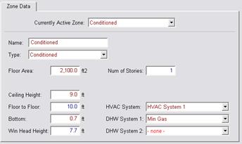
The software requires the user to enter the characteristics of one or more conditioned zones. Subdividing dwelling units into conditioned zones for input convenience or increased accuracy is optional.

Proposed Design
The zone is defined as conditioned, living or sleeping.
Standard Design
The standard design is conditioned.
Verification & Reporting
When the zone type is living or sleeping, this is reported as a Special Feature on the CF1R.
The total conditioned floor area (CFA) is the raised floor as well as the slab-on-grade floor area of the conditioned spaces measured from the exterior of exterior walls. Stairwell floor area is included in conditioned floor area as the horizontal area of the stairs and landings between two floors of each story of the house.
Proposed Design
The compliance software requires the user to enter the total conditioned floor area of each conditioned zone.
Standard Design
The standard design building has the same conditioned floor area and same conditioned zones as the proposed design.
Verification and Reporting
The conditioned floor area of each conditioned zone is reported on the CF1R.
2.5.3.1 Number of Stories of the Zone
Proposed Design
The number of stories of the zone.
Standard Design
The standard design is the same as the proposed design.
2.5.3.2 Ceiling Height
Proposed Design
The average ceiling height of the proposed design is the conditioned volume of air enclosed by the building envelope. The volume is determined from the total conditioned floor area and the average ceiling height.
Standard Design
The volume of the standard design building is the same as the proposed design.
Verification and Reporting
The conditioned volume of each zone is reported on the CF1R.
2.5.3.3 Free Ventilation Area
Free ventilation area is the window area adjusted to account for bug screens, window framing and dividers, and other factors.
Proposed Design
Free ventilation area for the proposed design is calculated as 5 percent of the fenestration area (rough opening), assuming all windows are operable.
Standard Design
The standard design value for free ventilation area is the same as the proposed design.
Verification and Reporting
Free ventilation is not reported on the CF1R.
2.5.3.4 Ventilation Height Difference
Ventilation height difference is not a user input.
Proposed Design
The default assumption for the proposed design is 2 feet for one-story buildings or one-story dwelling units and 8 feet for two or more stories (as derived from number of stories and other zone details).
Standard Design
The standard design modeling assumption for the elevation difference between the inlet and the outlet is 2 feet for one-story dwelling unit and 8 feet for two or more stories.
2.5.3.5 Zone Elevations
The elevation of the top and bottom of each zone is required to set up the air flow network.
Proposed Design
The user enters the height of the top surface the lowest floor of the zone relative to the ground outside as the “Bottom” of the zone. The user also enters the ceiling height (the floor to floor height (ceiling height plus the thickness of the intermediate floor structure) is calculated by the software).
Standard Design
The standard design has the same vertical zone dimensions as the proposed design.
Verification and Reporting
Vertical zone dimensions are shown on the CF1R.
2.5.3.6 Mechanical Systems
Proposed Design
The software requires the user to specify a previously defined HVAC system to provide heating and cooling for the zone and an indoor air quality (IAQ) ventilation system. The user may also specify a ventilation cooling system that applies to this and other conditioned zones.
Standard Design
The software assigns standard design HVAC, IAQ ventilation and ventilation cooling systems based on §150.1(c) and Table 150.1-A for the applicable climate zone.
2.5.3.7
Natural
Ventilation
Natural ventilation (from windows) is available during cooling mode when needed and available as shown in Table 2-19. The amount of natural ventilation used by computer software for natural cooling is the lesser of the maximum potential amount available and the amount needed to drive the interior zone temperature down to the natural cooling setpoint. When natural cooling is not needed or is unavailable no natural ventilation is used.
Computer software shall assume that natural cooling is needed when the building is in “cooling mode” and when the outside temperature is below the estimated zone temperature and the estimated zone temperature is above the natural cooling setpoint temperature. Only the amount of ventilation required to reduce the zone temperature down to the natural ventilation setpoint temperature is used and the natural ventilation setpoint temperature is constrained by the compliance software to be greater than the heating setpoint temperature.
|
Hour |
Cooling |
Venting |
Standard Heating |
Zonal Control Heating | |
|
Single Zone |
Living |
Sleeping | |||
|
1 |
78 |
Off |
65 |
65 |
65 |
|
2 |
78 |
Off |
65 |
65 |
65 |
|
3 |
78 |
Off |
65 |
65 |
65 |
|
4 |
78 |
Off |
65 |
65 |
65 |
|
5 |
78 |
Off |
65 |
65 |
65 |
|
6 |
78 |
68* |
65 |
65 |
65 |
|
7 |
78 |
68 |
65 |
65 |
65 |
|
8 |
83 |
68 |
68 |
68 |
68 |
|
9 |
83 |
68 |
68 |
68 |
68 |
|
10 |
83 |
68 |
68 |
68 |
65 |
|
11 |
83 |
68 |
68 |
68 |
65 |
|
12 |
83 |
68 |
68 |
68 |
65 |
|
13 |
83 |
68 |
68 |
68 |
65 |
|
14 |
82 |
68 |
68 |
68 |
65 |
|
15 |
81 |
68 |
68 |
68 |
65 |
|
16 |
80 |
68 |
68 |
68 |
65 |
|
17 |
79 |
68 |
68 |
68 |
68 |
|
18 |
78 |
68 |
68 |
68 |
68 |
|
19 |
78 |
68 |
68 |
68 |
68 |
|
20 |
78 |
68 |
68 |
68 |
68 |
|
21 |
78 |
68 |
68 |
68 |
68 |
|
22 |
78 |
68 |
68 |
68 |
68 |
|
23 |
78 |
68 |
68 |
68 |
68 |
|
24 |
78 |
Off |
65 |
65 |
65 |
*Venting starts in the hour the sun comes up.
2.5.4.1
Internal Thermal
mass 
Internal mass objects are completely inside a zone so that they do not participate directly in heat flows to other zones or outside. They are connected to the zone radiantly and convectively and participate in the zone energy balance by passively storing and releasing heat as conditions change.
Table 2-20 shows the standard interior conditioned zone thermal mass objects and the calculation of the simulation inputs that represent them.
|
Item |
Description |
Simulation Object |
|
Interior walls |
The area of one side of the walls completely inside the conditioned zone is calculated as the conditioned floor area of the zone minus ½ of the area of interior walls adjacent to other conditioned zones. The interior wall is modeled as a construction with 25% 2x4 wood framing and sheetrock on both sides. |
Wall exposed to the zone on both sides |
|
Interior floors |
The area of floors completely inside the conditioned zone is calculated as the difference between the CFA of the zone and the sum of the areas of zone exterior floors and interior floors over other zones. Interior floors are modeled as a surface inside the zone with a construction of carpet, wood decking, 2x12 framing at 16 in. o.c. with miscellaneous bridging, electrical and plumbing and a sheetrock ceiling below. |
Floor/ceiling surface exposed to the zone on both sides |
|
Furniture and heavy contents |
Contents of the conditioned zone with significant heat storage capacity and delayed thermal response, for example heavy furniture, bottled drinks and canned goods, contents of dressers and enclosed cabinets. These are represented by a 2 in. thick slab of wood twice as large as the conditioned floor area, exposed to the room on both sides. |
Horizontal wood slab exposed to the zone on both sides |
|
Light and thin contents |
Contents of the conditioned zone that have a large surface area compared to their weight, for example, clothing on hangers, curtains, pots and pans. These are assumed to be 2 BTU per square foot of conditioned floor area |
Air heat capacity (Cair) = CFA * 2 |
Proposed Design
The proposed design has standard conditioned zone thermal mass objects which are not user editable and are not a compliance variable. If the proposed design includes specific interior thermal mass elements that are significantly different from what is included in typical wood frame production housing, such as masonry partition walls, the user may include them. See also 2.5.6.4.
Standard Design
The standard design has standard conditioned zone thermal mass objects.
Verification and reporting
Any user input interior thermal mass elements are fully documented on the building plans and noted in the Special Features on the CF1R.
2.5.4.2
Thermostats and Schedules
Thermostat settings are shown in Table 2-19. The values for cooling, venting, and standard heating apply to the standard design run and are the default for the proposed design run. See the explanation later in this section regarding the values for zonal control.
Systems with no setback required by §110.2(c) (gravity gas wall heaters, gravity floor heaters, gravity room heaters, non-central electric heaters, fireplaces or decorative gas appliances, wood stoves, room air conditioners, and room air-conditioner heat pumps) are assumed to have a constant heating set point of 68 degrees and the same value as in column 1 of Table2-19 for the cooling set point in both the proposed design and standard design runs.
Proposed Design
The proposed design assumes a mandatory setback thermostat meeting the requirements of §110.2(c). Systems exempt from the requirement for a setback thermostat are assumed to have no setback capabilities.
Standard Design
The standard design has setback thermostat conditions based on the mandatory requirement for a setback thermostat. For equipment exempt from the setback thermostat requirement, the standard design has no setback thermostat capabilities.
Verification and reporting
When the proposed equipment is exempt from setback thermostat requirements this is shown as a Special Feature on the CF1R.
2.5.4.3 Determining Heating Mode vs. Cooling Mode
When the building is in the heating mode, the heating setpoints for each hour are set to the “heating” values in Table 2-19, the cooling setpoint is a constant 78°F and the ventilation setpoint is set to a constant 77°F. When the building is in the cooling mode the heating setpoint is a constant 60°F, and the cooling and venting setpoints are set to the values in Table 2-19.
The mode is dependent upon the outdoor temperature averaged over hours 1 through 24 of day 8 through day 2 prior to the current day (e.g., if the current day is June 21, the mode is based on the average temperature for June 13 through 20). When this running average temperature is equal to or less than 60°F, the building is in a heating mode. When the running average is greater than 60°F, the building is in a cooling mode.
Internal gains are consistent with the HERS Whole House specification:
California Energy Commission, HERS Technical 'Manual, California Energy Commission, High Performance Buildings and Standards Development Office. CEC-400-2008-012.except for modifications to include latent gains.
Daily internal gain is modified each month according to the multipliers shown in Table 2-21. These multipliers are derived from the number of daylight hours for each month. Identical inputs are used for both the proposed design and the standard design.
|
Month |
Multiplier |
Month |
Multiplier |
Month |
Multiplier |
|
Jan |
1.19 |
May |
0.84 |
Sep |
0.98 |
|
Feb |
1.11 |
Jun |
0.80 |
Oct |
1.07 |
|
Mar |
1.02 |
Jul |
0.82 |
Nov |
1.16 |
|
Apr |
0.93 |
Aug |
0.88 |
Dec |
1.21 |
The user enters exterior surfaces to define the envelope of the proposed design. The areas, construction assemblies, orientations, and tilts modeled are consistent with the actual building design and shall equal the overall roof/ceiling area with conditioned space on the inside and unconditioned space on the other side.
2.5.6.1
Ceilings below
Attics
Ceilings below attics are horizontal surfaces between conditioned zones and attics. The area of the attic floor is determined by the total area of ceilings below attics defined in conditioned zones.
Proposed Design
The software allows the user to define ceilings below attics and enter the area and select a construction assembly for each.
Standard Design
The standard design has the same ceiling below attic area as the proposed design. The standard design ceiling is constructed with 2x4 framed trusses and insulated with the R-value specified in §150.1(c) and Table 150.1-A for the applicable climate zone.
Verification and reporting
Ceiling below attic area and insulation are reported on the CF1R. Metal frame or SIP assemblies are reported as a special feature on the CF1R.
2.5.6.2
Non-Attic (Cathedral) Ceiling
and Roof 
Non-Attic Ceilings, also known as cathedral ceilings, are surfaces with roofing on the outside and finished ceiling on the inside but without an attic space.
Proposed Design
The software allows the user to define cathedral ceilings and enter the area and select a construction assembly for each. The user also enters the roof characteristics of the surface.
Standard Design
The non-attic ceiling/roof areas of the standard design building are equal to the non-attic ceiling/roof areas of the proposed design. The standard design roof and ceiling surfaces are assumed to be horizontal (no tilts). The standard design is modeled with the same construction assembly as the proposed design but with Package A insulation R-value. The aged reflectance and emittance of the standard design are determined by §150.1(c) and Table 150.1-A for the applicable climate zone.
Verification and reporting
Non-attic ceiling/roof area and construction are reported on the CF1R. Metal frame or SIP assemblies are reported as a special feature on the CF1R.
2.5.6.3
Exterior
Walls
Proposed Design
The software allows the user to define walls, enter the gross area and select a construction assembly for each. The user also enters the plan orientation (front, left, back or right) or plan azimuth (value relative to the front which is represented as 0 degrees) and tilt of the wall.
The wall areas modeled are consistent with the actual building design and the total wall area is equal to the gross wall area with conditioned space on the inside and unconditioned space or exterior conditions on the other side. Walls adjacent to unconditioned spaces with no solar gains (such as knee walls or garage walls) are entered as an interior wall with the zone on the other side as attic or garage and the compliance manager treats that wall as a demising wall. The unconditioned space is modeled as an unconditioned zone.
Standard Design
The gross exterior wall area in the standard design is equal to the gross exterior wall area of the proposed design. If the proposed wall area is framed wall, the gross exterior wall area of framed walls in the standard design (excluding knee walls) is equally divided between the four main compass points, north, east, south, and west. Window and door areas are subtracted from the gross wall area to determine the net wall area in each orientation. Walls adjacent to unconditioned space (garage walls) for all climate zones are wood framed, 2x4, 16-in. o.c., R-15 cavity insulation.
Verification and reporting
Exterior wall area and construction details are reported on the CF1R. Metal frame or SIP assemblies are reported as a special feature on the CF1R.
2.5.6.4
Exterior Thermal Mass
Constructions for standard exterior mass is supported but not implemented beyond the assumptions for typical mass.
The performance approach assumes that both the proposed design and standard design building have a minimum mass as a function of the conditioned area of slab floor and non-slab floor (see Section 2.5.4.1).
Mass such as concrete slab floors, masonry walls, double gypsum board and other special mass elements can be modeled. When the proposed design has more than the typical assumptions for mass in a building then each element of heavy mass is modeled in the proposed design, otherwise, the proposed design is modeled with the same thermal mass as the standard design.
Proposed Design
The proposed design may be modeled with the default 20 percent exposed mass/80 percent covered mass or with actual mass.
Standard Design
The conditioned slab floor in the standard design is assumed to be 20 percent exposed slab and 80 percent slab covered by carpet or casework. Interior mass assumptions as described in Section 2.5.4.1 are also assumed. No other mass elements are modeled in the standard design. The standard design mass is modeled with the following characteristics.
•The conditioned slab floor area (slab area) shall have a thickness of 3.5 inches; a volumetric heat capacity of 28 Btu/ft3-°F; a conductivity of 0.98 Btu-in/hr-ft2-°F. The exposed portion shall have a surface conductance of 1.3 Btu/hr-ft2-°F (no thermal resistance on the surface) and the covered portion shall have a surface conductance of 2.0 Btu/hr-ft2-°F, typical of a carpet and pad.
•The “exposed” portion of the conditioned non-slab floor area shall have a thickness of 2.0 inches; a volumetric heat capacity of 28 Btu/ft3-ºF; a conductivity of 0.98 Btu-in/hr-ft2-ºF; and a surface conductance of 1.3 Btu/hr-ft2-°F (no added thermal resistance on the surface). These thermal mass properties apply to the “exposed” portion of non-slab floors for both the proposed design and standard design. The covered portion of non-slab floors is assumed to have no thermal mass.
Verification and reporting
Exposed mass greater than 20 percent exposed slab on grade and any other mass modeled by the user shall be reported as a special feature on the CF1R.
2.5.6.5
Doors 
Proposed Design
The compliance software shall allow users to enter doors specifying the U-factor, area, and orientation. Doors to the exterior or to unconditioned zones are modeled as part of the conditioned zone. For doors with less than 50 percent glass area, the U-factor shall come from JA4, Table 4.5.1 (default U-factor 0.50). The glass area of the door, calculated as the sum of all glass surfaces plus two inches on all sides of the glass (to account for a frame), is modeled under the rules for fenestrations; the opaque area of the door is considered the total door area minus this calculated glass area. Doors with 50 percent or more glass area are modeled under the rules for fenestrations using the total area of the door.
When modeling a garage zone, large garage doors (metal roll-up or wood) are modeled with a 1.0 U-factor.
Standard Design
The standard design has the same door area for each dwelling unit as the proposed design. The standard design door area is distributed equally between the four main compass points—north, east, south and west. All doors are assumed to have a U-factor of 0.50. The net opaque wall area is reduced by the door area in the standard design.
Verification and reporting
Door area and construction are reported on the CF1R.
2.5.6.6
Fenestration
Fenestration is modeled with a U-factor and solar heat gain coefficient (SHGC). Acceptable sources of these values are National Fenestration Rating Council (NFRC), default tables from §110.6 of the standards, and Reference Appendix NA6.
In limited cases for certain site-built fenestration that is field fabricated the performance factors (U-factor, SHGC) may come from Nonresidential Reference Appendix NA6 as described in exception 4 to §150.1(c)3A.
There is no detailed model of chromogenic fenestration available at this time. As allowed by exception 3 to §150.1(c)3A, the lower rated labeled U-factor and SHGC may be used only when installed with automatic controls as noted in the exception. Chromogenic fenestration cannot be averaged with non-chromogenic fenestration.
Proposed Design
The compliance software allows users to enter individual fenestration or window types, the U-factor, SHGC, area, orientation, and tilt. Performance data (U-factors and SHGC) are either NFRC values or are taken from the Energy Commission default tables from §110.6 of the standards. In spaces other than sunspaces, solar gains from windows or skylights use the CSE default solar gain targeting.
Skylights are a fenestration with a slope of 60 degrees or more. Skylights are modeled as part of a roof.
Standard Design
If the proposed design fenestration area is less than 20 percent of the conditioned floor area, the standard design fenestration area is set equal to the proposed design fenestration area. Otherwise, the standard design fenestration area is set equal to 20 percent of the conditioned floor area. The standard design fenestration area is distributed equally between the four main compass points—north, east, south and west.
The standard design has no skylights.
The net wall area on each orientation is reduced by the fenestration area (and door area) on each facade. The U-factor and SHGC performance factors for the standard design are taken from the §150.1(c) and Table 150.1-A (Package A). Where Package A has no requirement, the SHGC is set to 0.50.
Verification and Reporting
Fenestration area, U-factor, SHGC, orientation, and tilt are reported on the CF1R.
2.5.6.7
Overhangs and
Sidefins
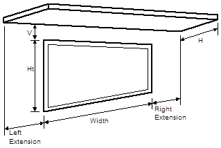
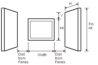
Proposed Design
Software users enter a set of basic parameters for a description of an overhang and sidefin for each individual fenestration or window area entry. The basic parameters include fenestration height, overhang/sidefin length, and overhang/sidefin height. Compliance software user entries for overhangs may also include fenestration width, Overhang left extension and overhang right extension. Compliance software user entries for sidefins may also include fin left extension and fin right extension for both left and right fins. Walls at right angles to windows may be modeled as sidefins.
Standard Design
The standard design does not have overhangs or side fins.
Verification and Reporting
Overhang and fin dimensions are reported on the CF1R.
2.5.6.8
Interior Shading
Devices
For both the proposed and standard design, all windows are assumed to have draperies and skylights are assumed to have no interior shading. Window medium drapes are closed at night and half open in the daytime hours. Interior shading is not a compliance variable and is not user editable.
2.5.6.9
Exterior Shading
For both the proposed and standard design, all windows are assumed to have bug screens and skylights are assumed to have no exterior shading. Exterior shading is modeled as an additional glazing system layer using the ASHWAT calculation.
Proposed Design
The compliance software shall require the user to accept the default exterior shading devices, which are bug screens for windows and none for skylights. Credit for shading devices that are allowable for prescriptive compliance are not allowable in performance compliance.
Standard Design
The standard design shall assume bug screens. The standard design does not have skylights.
2.5.6.9.1 Walls and
Floors Between Zones
The user must model unconditioned attached zones such as garages, crawl spaces, and basements.
Proposed Design
The user inputs the area and construction of walls and floors between zones.
Standard Design
The standard design shall have the same wall and floor areas and the constructions meet §150.1(c) and Table 150.1-A.
Verification and Reporting
Areas and construction of interzone surfaces is reported on the CF1R.
2.5.6.10 Slab on grade
floors
Proposed Design
The software allows users to enter areas and exterior perimeter of slabs that are heated or unheated, covered or exposed slab, and with or without with slab edge insulation. Perimeter is the length of wall between conditioned space and the exterior, but does not include edges that cannot be insulated, such as between the house and the garage. The default condition for the proposed design is that 80 percent of each slab area is carpeted or covered by walls and cabinets, and 20 percent is exposed. Inputs other than the default condition require that carpet and exposed slab conditions are documented on the construction plans.
When the proposed heating distribution is radiant floor heating (heated slab), the software user will identify that the slab is heated and model the proposed slab edge insulation. The mandatory minimum requirement is R-5 insulation in climate zones 1-15 and R-10 in climate zone 16, (§110.8 (g) Table 110.8-A).
Standard Design
The standard design perimeter lengths and slab on grade areas are the same as the proposed design. Eighty percent of standard design slab area is carpeted and 20 percent is exposed. For the standard design, an unheated slab edge has no insulation with the exception of climate zone 16, which assumes R-7 to a depth of 16 inches. The standard design for a heated slab is a heated slab with the mandatory slab edge insulation of R-5 in climate zones 1-15 and R-10 in climate zone 16.
Verification and Reporting
Slab areas, perimeter lengths and inputs of other than the default condition are reported on the CF1R.
2.5.6.11 Raised
Floors
Proposed Design
The software allows the user to input floor areas and constructions for raised floors over a crawl space, over exterior (garage or unconditioned), over a controlled ventilation crawl space, and raised concrete floors. The proposed floor area is consistent with the actual building design.
Standard Design
The standard design is the area and construction as the proposed design, except the thermal characteristics meet §150.1(c) and Table 150.1-A.
Verification and Reporting
Raised floor areas and constructions are reported on the CF1R.