This section addresses the requirements for thermal control of the opaque portion of the building shell or envelope.
This section contains mandatory measures that are not specific to one envelope component.
3.2.1.1 Mandatory Requirements
A. Certification of Insulation Materials
Manufacturers must certify that insulating materials comply with California Quality Standards for Insulating Materials, which became effective January 1, 1982. It ensures that insulation sold or installed in the state performs according to the stated R-values and meets minimum quality, health, and safety standards.
Builders may not install insulating materials, unless the product has been certified by the Department of Consumer Affairs, Bureau of Electronic and Appliance Repair, Home Furnishing and Thermal Insulation. Builders and enforcement agencies shall use the Department of Consumer Affairs Directory of Certified Insulation Materials to verify certification of the insulating material. If an insulating product is not 'listed in the most recent edition of the directory, contact the Department of Consumer Affairs, Bureau of Bureau of Electronic and Appliance Repair, Home Furnishing and Thermal Insulation Program, at (916) 999-2041 or by e-mail: HomeProducts@dca.ca.gov.
Where applicable, the R-value of cavity and/or continuous insulation, or the overall assembly U-factor, may be used to demonstrate compliance with required insulation levels. Reference insulation values are provided in the Reference Appendix JA4, where assembly U-factors are shown for various assemblies and components. U-factors represent the actual thermal conductance of the assembly, including air film coefficients, framing factors, and all layers used to construct the assembly. Assemblies not listed in JA4 tables may calculate U-factors using the assembly calculator in the public domain software, CBECC-COM.
B. Urea Formaldehyde Foam Insulation
The mandatory measures restrict the use of urea formaldehyde foam insulation. The restrictions are intended to limit human exposure to formaldehyde, which is a volatile organic chemical known to be harmful to humans.
If foam insulation is used that has urea formaldehyde, it must be installed on the exterior side of the wall (not in the cavity of framed walls), and a continuous barrier must be placed in the wall construction to isolate the insulation from the interior of the space. The barrier must be 4-mil (0.1 mm) thick polyethylene or equivalent.
C. Flame Spread Rating of Insulation
The California Quality Standards for Insulating Materials also require that all exposed installations of faced mineral fiber and mineral aggregate insulations use fire retardant facings that have been tested and certified not to exceed a flame spread of 25 and a smoke development rating of 450. Insulation facings that do not touch a ceiling, wall, floor surface, and faced batts on the underside of roofs with an air space between the ceiling and facing are considered exposed applications.
Flame spread ratings and smoke density ratings are shown on the insulation or packaging material or may be obtained from the manufacturer.
D. Infiltration and Air Leakage
All joints and other openings in the building envelope that are potential sources of air leakage must be caulked, gasketed, weatherstripped, or otherwise sealed to limit air leakage into or out of the building. This applies to penetrations for pipes and conduits, ducts, vents, and other openings. It means that all gaps between wall panels, around doors, and other construction joints must be well sealed. Ceiling joints, lighting fixtures, plumbing openings, doors, and windows should all be considered as potential sources of unnecessary energy loss due to infiltration.
No special construction requirements are necessary for suspended (T-bar) ceilings, provided they meet the requirements of §110.8(e). Standard construction is typically adequate for meeting the infiltration/exfiltration requirements unless an air barrier is required. (See Section 3.2.1.2).
E. Mandatory Insulation Requirements (Newly Constructed Buildings)
Newly constructed nonresidential and high-rise residential buildings and hotels/motels must meet mandatory insulation requirements for opaque portions of the building that separate conditioned spaces from unconditioned spaces or ambient air. The U-factor for each assembly type shall not exceed the values listed in Table 3-2. Determining the total weight-averaged U-factor is allowed for all assembly types except for light and heavy mass walls. Joint Appendix JA-4 of the Reference Appendices illustrates the allowed procedure for calculating U-factors. The representative constructions that meet these requirements are shown in parentheses. U-factors allow greater flexibility in the design choice of components making up a given assembly that meet the maximum U-factor requirement and design conditions of the envelope.
An exception is specified that exempts buildings designed as data centers with high, constant server loads from the mandatory minimum requirements. To qualify for this exception, it should have a design computer room process load of 750 kW or greater.
3.2.1.2 Prescriptive Requirements
A. Air Barrier
Table cB of the Energy Standards specifies requirements for air barriers in nonresidential buildings. Air barrier requirements apply to nonresidential buildings, but not relocatable public school buildings, and are effectively mandatory requirements, since they cannot be traded off in the performance approach. These requirements reduce the overall building air leakage rate. The reduction in air leakage can be met with a continuous air barrier that seals all joints and openings in the building envelope and is composed of one of the following:
1. Materials having a maximum air permeance of 0.004 cfm/ft2 (see Table 3-1 below).
2. Assemblies of materials and components having an average air leakage not exceeding 0.04 cfm/ft2.
3. An entire building having an air leakage rate not exceeding 0.40 cfm/ft2.
The air leakage requirements stipulated in §140.3 must be met, either by demonstrating that component air leakage or whole-building air leakage of 0.4 cfm/ft2 is not exceeded. This requirement must be met regardless of the compliance path chosen, so it is effectively mandatory.
|
|
MATERIALS AND THICKNESS |
|
MATERIALS AND THICKNESS |
|
1 |
Plywood – min. 3/8 inches thickness |
9 |
Built up roofing membrane |
|
2 |
Oriented strand board – min. 3/8 inches thickness |
10 |
Modified bituminous roof membrane |
|
3 |
Extruded polystyrene insulation board – min. ½ inches thickness |
11 |
Fully adhered single-ply roof membrane |
|
4 |
Foil-back polyisocyanurate insulation board – min. ½ inches thickness |
12 |
A Portland cement or Portland sand parge, or a gypsum plaster, each with min. 5/8 inches thickness |
|
5 |
Closed cell spray foam with a minimum density of 2.0 pcf and a min. 1½ inches thickness |
13 |
Cast-in-place concrete,
or |
|
6 |
Open cell spray foam with a density no less than 0.4 pcf and no greater than 1.5 pcf, and a min. 5½ inches thickness |
14 |
Fully grouted concrete block masonry |
|
7 |
Exterior or interior gypsum board min. 1/2 inches thickness |
15 |
Sheet steel or sheet aluminum |
|
8 |
Cement board – min. 1/2
inches |
_____ |
_______________________ |
3.2.2.1 Mandatory Measures
A. Roof/Ceiling Insulation
1. Metal Building: Weighted average U-factor of U-0.098 (R-19 screw down roof, no thermal blocks).
2. Wood-Framed and Others: Weighted average U-factor of U-0.075 (2x4 rafter, R-19 insulation).
B. Insulation Placement on Roof/Ceilings
Insulation installed on top of suspended (T-bar) ceilings with removable ceiling panels may not be used to comply with the Energy Standards unless the installation meets the criteria described in the Exception to §120.7(a)3 below. Insulation may be installed in this location for other purposes such as for sound control, but it will have no value in terms of meeting roof/ceiling insulation requirements of the Energy Standards.
Acceptable insulation installations include placing the insulation in direct contact with a continuous roof or ceiling that is sealed to limit infiltration and exfiltration as specified in §110.7, including, but not limited to, placing insulation either above or below the roof deck or on top of a drywall ceiling.
When insulation is installed at the roof in nonresidential buildings, the space between the ceiling and the roof is considered to be either directly or indirectly conditioned space. Therefore, this space must not include fixed vents or openings to the outdoors or to unconditioned spaces. This space is not considered an attic for complying with California Building Code (CBC) attic ventilation requirements. Vents that do not penetrate the roof deck and that are designed for wind resistance for roof membranes are acceptable.
Exception to §120.7(a)3: When there are conditioned spaces with a combined floor area no greater than 2,000 square feet in an otherwise unconditioned building, and when the average height of the space between the ceiling and the roof over these spaces is greater than 12 feet, insulation placed in direct contact with a suspended ceiling with removable ceiling panels shall be an acceptable method of reducing heat loss from a conditioned space and shall be accounted for in heat loss calculations.
C. Wet Insulation Systems
Wet insulation systems are roofing systems where the insulation is installed above the roof’s waterproof membrane. Water can penetrate this insulation material and affect the energy performance of the roofing assembly in wet and cool climates. In Climate Zones 1 and 16, the insulating R-value of continuous insulation materials installed above the waterproof membrane of the roof must be multiplied by 0.8 before choosing the table column in Reference Appendix JA4 for determining assembly U-factor. See the footnotes in the Reference Appendix JA4 for Tables 4.2.1 through 4.2.7.
D. Roofing Products: Solar Reflectance and Thermal Emittance
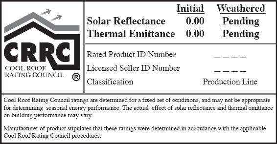
Roofing products must be tested and labeled by the Cool Roof Rating Council (CRRC), and liquid-applied products must meet minimum standards for performance and durability per §110.8(i)4. Installing cool roofs is not a mandatory measure. However, to receive credit for product performance, the reflectance and thermal emittance of a roofing product must be tested and certified according to CRRC procedures. If a CRRC rating is not obtained for roofing products, default values for reflectance and emittance must be used.
1. Rating and Labeling
When a cool roof is installed to meet the prescriptive requirement or when it is used for compliance credit, the products must be tested and labeled by the CRRC as specified in §10-113. The CRRC is the supervisory entity responsible for certifying cool roof products. The CRRC test procedure is documented in CRRC-1, the CRRC Product Rating Program Manual. This test procedure includes tests for both solar reflectance and thermal emittance. See Figure 3-2 for an example of an approved CRRC product label.
2. Solar Reflectance, Thermal Emittance, and Solar Reflectance Index (SRI)
To demonstrate compliance with the Energy Standards, all cool roofing products must be certified and labeled according to CRRC procedures. The CRRC certification includes solar reflectance and thermal emittance. There are three kinds of solar reflectance listed in the CRRC’s Rated Product Directory:
1. Initial solar reflectance.
2. 3-year aged solar reflectance.
3. Accelerated aged solar reflectance.
All requirements of the Energy Standards are based on the 3-year aged solar reflectance. However, if the aged value for the reflectance is not available in the CRRC’s Rated Product Directory, then the aged value shall be derived from the CRRC initial value or an accelerated testing process. Until the appropriate aged rated value for the reflectance is posted in the directory, the equation below can be used to calculate the aged rated solar reflectance or a new method of testing is used to find the accelerated solar reflectance.
Aged Reflectancecalculated=(0.2+ β[ρinitial – 0.2])
Where,
ρinitial = Initial Reflectance listed in the CRRC Rated Product Directory
β= 0.65 for Field Applied Coating, or 0.70 for Not a Field-Applied Coating
The Energy Standards do not distinguish between initial and aged thermal emittance, meaning that either value can be used to demonstrate compliance with the Energy Standards. If a manufacturer fails to obtain CRRC certificate for its roofing products, the following default aged solar reflectance and thermal emittance values must be used for compliance:
a. For asphalt shingles, 0.08/0.75.
b. For all other roofing products, 0.10/0.75.
The temperature of a surface depends on the solar radiation incident, surface reflectance, and emittance. The SRI measures the relative steady-state surface temperature of a surface with respect to standard white (SRI=100) and standard black (SRI=0) under the standard solar and ambient condition. A calculator has been produced by Lawrence Berkeley National Laboratory that calculates the SRI by designating the solar reflectance and thermal emittance of the desired roofing material. The calculator can be found at http://www.energy.ca.gov/title24/2016standards/documents/solar_reflectance/. To calculate the SRI, the 3-year aged value of the roofing product must be used. By using the SRI calculator, a cool roof may prescriptively comply with an emittance lower than 0.85, as long as the aged solar reflectance is higher or a lower aged solar reflectance with a much higher than 0.85 emittance.
3. Field-Applied Liquid Coatings
Liquid roof coatings applied to low-sloped roofs in the field as the top surface of a roof covering shall comply with the following mandatory requirements and descriptions. There are several liquid products, including elastomeric coatings and white acrylic coatings that qualify for field-applied liquid coatings. The Energy Standards specify minimum performance and durability requirements for field-applied liquid coatings in Table 110.8-C. These requirements do not apply to industrial coatings that are factory-applied, such as metal roof panels. The requirements address elongation, tensile strength, permeance, and accelerated weathering. The requirements depend on the type of coating and are described in greater detail below.
a. Aluminum-Pigmented Asphalt Roof Coatings
Aluminum-pigmented coatings are silver-colored coatings that are commonly applied to modified bitumen and other roofing products. The coating has aluminum pigments that float to the surface of the coating and provides a shiny, surface. Because of the shiny surface and the physical properties of aluminum, these coatings have a thermal emittance below 0.75, which is the minimum rating for prescriptive compliance. The performance approach is typically used to achieve compliance with these coatings.
This class of field-applied liquid coatings shall be applied across the entire surface of the roof and meet the dry mil thickness or coverage recommended by the coating manufacturer, taking into consideration the substrate on which the coating will be applied. Also, the aluminum-pigmented asphalt roof coatings shall be manufactured in accordance with ASTM D2824. Standard specification is also required for aluminum-pigmented asphalt roof coatings, nonfibered, asbestos-fibered, and fibered without asbestos that are suitable for applying to roofing or masonry surfaces by brush or spray. Use ASTM D6848, Standard Specification for Aluminum Pigmented Emulsified Asphalt used as a Protective Coating for Roofing, installed in accordance with ASTM D3805, Standard Guide for Application of Aluminum-Pigmented Asphalt Roof Coatings.
b. Cement-Based Roof Coatings
This class of coatings consists of a layer of cement and has been used for a number of years in California’s Central Valley and other regions. These coatings may be applied to almost any type of roofing product. Cement-based coatings shall be applied across the entire roof surface to meet the dry mil thickness or coverage recommended by the manufacturer. Also, cement-based coatings shall be manufactured to contain no less than 20 percent Portland cement and meet the requirements of ASTM D822, ASTM C1583, and ASTM D5870.
c. Other Field-Applied Liquid Coatings
Other field-applied liquid coatings include elastomeric and acrylic-based coatings. These coatings must be applied across the entire surface of the roof to meet the dry mil thickness or coverage recommended by the coating manufacturer, taking into consideration the substrate on which the coating will be applied. The field-applied liquid coatings must be tested to meet performance and durability requirements as specified in Table 110.8-C of the Energy Standards or the minimum performance requirements of ASTM C836, D3468, D6083, or D6694, whichever are appropriate to the coating material.
3.2.2.2 Prescriptive Measures
A. Insulation Requirements − Exterior Roofs and Ceilings
Under the prescriptive requirements, roofs or ceilings must have an assembly U-factor equal to or lower than the U-factor criterion for nonresidential or high-rise residential buildings. (See Table 3-2The U-factor values for exterior roofs and ceilings from Reference Appendix JA4 must be used to determine compliance with the maximum assembly U-factor requirements. Alternatively, the assembly calculator that is incorporated into CBECC-COM, the public domain program, can be used to determine U-factors for assemblies and/or components not listed in JA4 tables.
The metal building roof prescriptive requirement has been updated in the 2016 Energy Standards to require a filled cavity insulation technique for improved performance. In the past, a common technique for standing seam metal roofs is to drape a layer of insulation over the purlins, using thermal blocks where the insulation is compressed at the supports. (See Figure 3-3.)
|
Building Type |
Climate Zones | ||||||||
|
1 |
2 |
3 |
4 |
5 |
6 |
7 |
8 | ||
|
Nonresidential |
Metal Bldg |
0.041 |
0.041 |
0.041 |
0.041 |
0.041 |
0.041 |
0.041 |
0.041 |
|
Wood-Framing & Other framing type |
0.034 |
0.034 |
0.034 |
0.034 |
0.034 |
0.049 |
0.049 |
0.049 | |
|
High-Rise Residential |
Metal Bldg |
0.041 |
0.041 |
0.041 |
0.041 |
0.041 |
0.041 |
0.041 |
0.041 |
|
Wood-framing & Other framing type |
0.028 |
0.028 |
0.034 |
0.028 |
0.034 |
0.034 |
0.039 |
0.028 | |
|
Relocatable Public School Buildings |
Metal Bldg |
0.041 |
0.041 |
0.041 |
0.041 |
0.041 |
0.041 |
0.041 |
0.041 |
|
Non-Metal Bldg |
0.034 |
0.034 |
0.034 |
0.034 |
0.034 |
0.034 |
0.034 |
0.034 | |
|
Building Type |
Climate Zones | ||||||||
|
9 |
10 |
11 |
12 |
13 |
14 |
15 |
16 | ||
|
Nonresidential |
Metal Bldg |
0.041 |
0.041 |
0.041 |
0.041 |
0.041 |
0.041 |
0.041 |
0.041 |
|
|
Wood-Framing & Other framing type |
0.034 |
0.034 |
0.034 |
0.034 |
0.034 |
0.034 |
0.034 |
0.034 |
|
High-Rise Residential |
Metal Bldg |
0.041 |
0.041 |
0.041 |
0.041 |
0.041 |
0.041 |
0.041 |
0.041 |
|
|
Wood-Framing & Other framing type |
0.028 |
0.028 |
0.028 |
0.028 |
0.028 |
0.028 |
0.028 |
0.028 |
|
Relocatable Public School Buildings |
Metal Bldg |
0.041 |
0.041 |
0.041 |
0.041 |
0.041 |
0.041 |
0.041 |
0.041 |
|
Non-Metal Bldg |
0.034 |
0.034 |
0.034 |
0.034 |
0.034 |
0.034 |
0.034 |
0.034 | |
Summary of Tables 140.3-B, 140.3-C, and 140.3-D of the Energy Standards
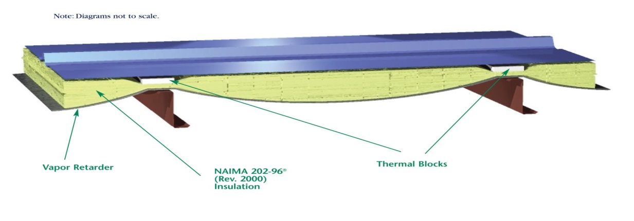
Source: North American Insulation Manufacturers Association (NAIMA)
Recent studies show that the thermal performance of this assembly is not as good as estimated. Therefore, there are significant benefits to using the “filled cavity” approach, shown below.
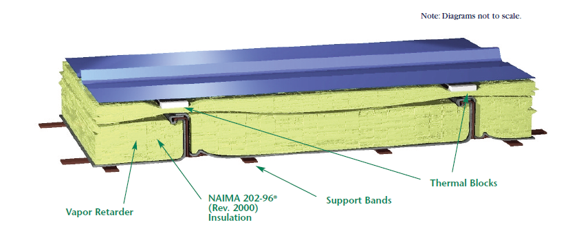
Source: North American Insulation Manufacturers Association (NAIMA)
A rigid polyisoyanurate (“polyiso”) thermal block with a minimum R-value of R-3.5 should be installed at the supports (a 1-inch-thick thermal block is recommended). The first rated R-value of the insulation is for faced insulation installed between the purlins. The second rated R-value of insulation represents unfaced insulation installed above the first layer, perpendicular to the purlins and compressed when the metal roof panels are attached. A supporting structure retains the bottom of the first layer at the prescribed depth required for the full thickness of insulation.
The bottom layer of insulation should completely fill the space between the purlins, and the support bands should be installed tightly to prevent the insulation from sagging.
The configuration above, which corresponds to two layers of R-19 and R-10 insulation, corresponds to the prescriptive requirement of U-0.041, but other insulation combinations exceeding the minimum requirement are readily achievable.
B. Thermal Emittance and Solar Reflectance
The prescriptive requirements call for roofing products to meet the solar reflectance and thermal emittance in both low-sloped and steep-sloped roof applications for nonresidential buildings. A qualifying roofing product under the prescriptive approach for a nonresidential building must have an aged solar reflectance and thermal emittance greater than or equal to that the values indicated in Table 3-3 below. Table 3-4 is for high-rise residential buildings and hotel/motel guest rooms, and Table 3-5 is for relocatable public school buildings where the manufacturer certifies use in all climate zones.
|
|
Climate Zones | |||||||||||||||||
|
1 |
2 |
3 |
4 |
5 |
6 |
7 |
8 |
9 |
10 |
11 |
12 |
13 |
14 |
15 |
16 | |||
|
Roofing Products |
Low |
Aged Reflectance |
0.63 |
0.63 |
0.63 |
0.63 |
0.63 |
0.63 |
0.63 |
0.63 |
0.63 |
0.63 |
0.63 |
0.63 |
0.63 |
0.63 |
0.63 |
0.63 |
|
Emittance |
0.75 |
0.75 |
0.75 |
0.75 |
0.75 |
0.75 |
0.75 |
0.75 |
0.75 |
0.75 |
0.75 |
0.75 |
0.75 |
0.75 |
0.75 |
0.75 | ||
|
SRI |
75 |
75 |
75 |
75 |
75 |
75 |
75 |
75 |
75 |
75 |
75 |
75 |
75 |
75 |
75 |
75 | ||
|
Steep |
Aged Reflectance |
0.20 |
0.20 |
0.20 |
0.20 |
0.20 |
0.20 |
0.20 |
0.20 |
0.20 |
0.20 |
0.20 |
0.20 |
0.20 |
0.20 |
0.20 |
0.20 | |
|
Emittance |
0.75 |
0.75 |
0.75 |
0.75 |
0.75 |
0.75 |
0.75 |
0.75 |
0.75 |
0.75 |
0.75 |
0.75 |
0.75 |
0.75 |
0.75 |
0.75 | ||
|
SRI |
16 |
16 |
16 |
16 |
16 |
16 |
16 |
16 |
16 |
16 |
16 |
16 |
16 |
16 |
16 |
16 | ||
Energy Standards Table 140.3-B
|
|
Climate Zones | |||||||||||||||||
|
1 |
2 |
3 |
4 |
5 |
6 |
7 |
8 |
9 |
10 |
11 |
12 |
13 |
14 |
15 |
16 | |||
|
Roofing Products |
Low |
Aged Reflectance |
NR |
NR |
NR |
NR |
NR |
NR |
NR |
NR |
0.55 |
0.55 |
0.55 |
NR |
0.55 |
0.55 |
0.55 |
NR |
|
Emittance |
NR |
NR |
NR |
NR |
NR |
NR |
NR |
NR |
0.75 |
0.75 |
0.75 |
NR |
0.75 |
0.75 |
0.75 |
NR | ||
|
SRI |
64 |
64 |
64 |
64 |
64 |
64 |
64 |
64 |
64 |
64 |
64 |
64 |
64 |
64 |
64 |
64 | ||
|
|
Steep |
Aged Reflectance |
NR |
0.20 |
0.20 |
0.20 |
0.20 |
0.20 |
0.20 |
0.20 |
0.20 |
0.20 |
0.20 |
0.20 |
0.20 |
0.20 |
0.20 |
NR |
|
Emittance |
0.75 |
0.75 |
0.75 |
0.75 |
0.75 |
0.75 |
0.75 |
0.75 |
0.75 |
0.75 |
0.75 |
0.75 |
0.75 |
0.75 |
0.75 |
0.75 | ||
|
SRI |
16 |
16 |
16 |
16 |
16 |
16 |
16 |
16 |
16 |
16 |
16 |
16 |
16 |
16 |
16 |
16 | ||
Energy Standards Table 140.3-C
|
Roofing Products |
Aged Reflectance |
Emittance |
|
Low-Sloped |
0.63 |
0.75 |
|
SRI |
75 | |
|
Steep-Sloped |
0.20 |
0.75 |
|
SRI |
16 | |
If the aged value for the solar reflectance is not available in the CRRC Rated Product Directory, then the equation in Section 3.2.2.1D (Aged Reflectancecalculated=(0.2+ β[ρinitial – 0.2])) can be used until the aged rated value for the reflectance is posted in the directory.
There are three exceptions to the minimum prescriptive requirements for solar reflectance and thermal emittance:
1. Roof area covered by building-integrated photovoltaic panels and building-integrated solar thermal panels is not required to meet the cool roof requirements.
2. If the roof construction has a thermal mass like gravel, concrete pavers, stone, or other materials with a weight of at least 25 lb/ft² over the roof membrane, then it is exempt from the above requirements for solar reflectance and thermal emittance.
3. Wood-framed roofs in climate zones 3 and 5 with a U- factor of 0.034 are exempt from the low-sloped cool roof requirement.
Where a low-sloped nonresidential roof’s aged reflectance is less than the prescribed requirement, insulation tradeoffs are available. By increasing the insulation level of a roof, a roofing product with a lower reflectance than the prescriptive requirements can be used to meet the cool roof requirements. The appropriate U-factor can be determined from Table 3-6 for nonresidential buildings based on roof type, climate zone and aged reflectance of at least 0.25.
|
Aged Solar Reflectance |
Metal Building Climate Zone 1-16 U-factor |
Wood-Framed and Other Climate Zone 6 & 7 U-factor |
Wood Framed and Other All Other Climate Zones U-factor |
|
0.62-0.56 |
0.038 |
0.045 |
0.032 |
|
0.55-0.46 |
0.035 |
0.042 |
0.030 |
|
0.45-0.36 |
0.033 |
0.039 |
0.029 |
|
0.35 -0.25 |
0.031 |
0.037 |
0.028 |
Energy Standards Table 140.3
3.2.2.3 Performance Approach – Compliance Options
The compliance options process allows the Energy Commission to review and gather public input regarding the merits of new compliance techniques, products, materials, designs, or procedures to demonstrate compliance for newly constructed buildings and additions and alterations to existing buildings.
A. Aggregate Default Roof Reflectance Properties
Some low-sloped roofs of nonresidential buildings use aggregate material made of gravel or crushed stone that is 3/4" or smaller, as the surface layer under a ballasted roof. Such roofing cannot be accurately tested via CRRC procedures because some of the aggregate can become damaged in transit, affecting the performance.
The Energy Commission has stipulated aged reflectance and emittance values that can be used for these types of products that have been tested via ASTM procedures. The default reflectance and emittance values may be used below in the performance compliance approach or prescriptive tradeoff with increased insulation (Table 140.3 of the Energy Standards).
|
Aggregate Size |
Required Tested Initial Solar Reflectance |
Default Aged Solar Reflectance |
Default Thermal Emittance |
|
Built-Up Roofs Size 6-8 conforming to ASTM D448 and ASTM D1863 |
0.50 |
0.48 |
0.85 |
|
Ballasted Roofs Size 2-4 conforming to ASTM D448 |
0.45 |
0.40 |
0.85 |
For example, aggregate with size 2-4 meeting the requirements must have a tested solar reflectance of at least 0.45 to use a default aged reflectance value of 0.40 in the performance method.
Eligibility criteria for aggregate used as the surface layer of low-sloped roofs:
1. Aggregate shall have a tested initial solar reflectance that meets or exceeds 0.50 for built-up roofs and 0.45 for ballasted roofs using the ASTM E1918 test procedure conducted by an independent laboratory meeting the requirement of §10-113(d)4
2. Aggregate shall have a label on bags or containers of the aggregate material stating
(a) the tested initial solar reflectance of the material conforming to ASTM D1863, and (b) the size of the material conforming to ASTM D448.
Example 3-1
Question:
According to the provisions of the Energy Standards, are cool roofs optional for nonresidential buildings or high-rise residential buildings?
Answer:
The answer depends on the compliance approach you chose. For prescriptive compliance, compliance with solar reflectance and thermal emittance, or SRI is required where indicated in Energy Standards Tables 140.3-B, C, and D. In the performance approach, reflectance, and emittance values less than the minimum prescriptive requirements may be used; however, any deficit that results from this choice must be made up by improving other energy efficiency features in the building, which include envelope, space-conditioning system, and lighting systems.
Example 3-2
Question:
Must all roofing materials used in California, whether cool roof or not, be certified by the CRRC and labeled accordingly?
Answer:
No, but it does depend on the compliance approach you are using. A roof repair, such as for a leak, does not require the roofing product to be cool roof and/or certified by the CRRC.
If you are altering your roof, such as a new reroof, then either the prescriptive envelope component approach or the performance approach can be used for compliance.
In these compliance cases, the answer is yes, the roof must be certified and labeled by CRRC for nonresidential roofs. If you are using the performance approach to receive compliance credit, you can either obtain a CRRC certification, or use a default solar reflectance of 0.10 and thermal emittance of 0.75. Using default values instead of CRRC certificates may result in a significant energy penalty that must be made up by increasing energy efficiency in other building features. The default reflectance for asphalt roofs is different than tile and metal roofing products.
Example 3-3
Question:
Can I use solar reflectance and thermal emittance data generated by any nationally recognized and well-respected laboratory in lieu of CRRC ratings? Can in-house testing by the manufacturer be used to qualify my product?
Answer:
No. Only CRRC ratings from the product directory list can be used to establish cool roof product qualification for standards compliance. The CRRC process requires use of a CRRC-accredited laboratory (under most circumstances, an "Accredited Independent Testing Laboratory (AITL) defined by the CRRC program.) Any testing laboratory can become an AITL by following the CRRC accreditation process and satisfying the requirements. The roster of CRRC-accredited laboratories is posted on the CRRC website (http://www.coolroofs.org).
Example 3-4
Question:
Can the reflectance and emittance requirements of ENERGY STAR® cool roofs be substituted for standards requirements?
Answer
No. Only roofing products which are listed by the CRRC in its Rated Product Directory can be used to the standards. CRRC is the only organization that has met the criteria set in §10-113.
Example
3-5
Question:
Can I claim to have a cool roof, or can I get anything higher than a default reflectance, if my roof does not meet the field-applied coating performance requirements of the Energy Standards?
Answer:
No, you cannot claim to have a cool roof and you cannot claim higher energy credits if your roof does not meet the coating performance requirements of the Energy Standards for field-applied coatings.
Example 3-6
Question:
How does a product get CRRC cool roof certification?
Answer:
Any party wishing to have a product or products certified by CRRC should contact the CRRC toll-free (866) 465-2523 from inside the United States or (510) 482-4420, ext. 215, or email info@coolroofs.org. In addition, CRRC publishes the procedures in the CRRC-1 Program Manual, available for free on http://www.coolroofs.org or by calling the CRRC. However, working with CRRC staff is strongly recommended.
Example 3-7
Question:
Do alterations to the roof of an unconditioned building trigger cool roof requirements?
Answer:
No, alterations to the roof of an unconditioned building do not trigger cool roof requirements. In general, the lighting requirements are the only requirements applicable for both newly constructed and altered unconditioned buildings; this includes §140.3(c), the skylight requirements. Building envelope (other than skylight requirements) and space-conditioning requirements do not apply to unconditioned buildings.
Example 3-8
Question:
What happens if I have a low-sloped roof on most of my buildings and steep-sloped roof on another portion of the roof? Do I have to meet the two different sets of rules in §140.3(a)1Ai and ii?
Answer:
Yes, your building would have to meet both the low-sloped requirement and the steep-sloped roof requirements for the respective area.
Example 3-9
Question:
I am installing a garden roof (roofs whose surface is composed of soil and plants) on top of an office building. Although garden roofs are not cool roofs by their reflectance properties, will they be allowed under the Energy Standards?
Answer:
Yes, the Energy Commission considers a garden roof as a roof with thermal mass on it.
Under Exception 4 to §140.3(a)1Ai, if a garden roof has a dry unit weight of 25 lb/ft², then the garden roof is equivalent to cool roof.
3.2.3.1 Mandatory Requirements
A. Wall Insulation
1. Metal Building: Weighted average U-factor of U-0.113 (single layer of R-13 batt insulation).
2. Metal-Framed: Weighted average U-factor of U-0.151 (R-8 continuous insulation, or R-13 batt insulation between studs and 1/2” of continuous rigid insulation of R-2). It may be possible to meet the area-weighted average U-factor without continuous insulation, if the appropriate siding materials are used.
3. Light Mass Walls: 6 inches or greater hollow core concrete masonry unit having a U-factor not exceeding 0.440 (partially grouted with insulated cells).
4. Heavy Mass Walls: 8 inches or greater hollow core concrete masonry unit having a U-factor not exceeding 0.690 (solid grout concrete, normal weight, 125 lb/ft3).
5. Wood-Framed and Others: Weighted average U-factor of U-0.110 (R-11 batt insulation).
6. Glass Spandrel Panels and Glass Curtain Wall: Weighted average U-factor of U-0.280.
Exception: Buildings designed as data centers with high, constant server loads from the mandatory minimum requirements are exempt. To qualify for this exception, it should have a design computer room process load of 750 kW or greater.
3.2.3.2 Prescriptive Requirements
Under the prescriptive requirements, exterior walls must have an assembly U-factor equal to or lower than the U-factor criterion for nonresidential and high-rise residential buildings in Table 3-8.
The U-factor for exterior walls from Reference Appendix JA4 must be used to determine compliance with the assembly U-factor requirements. The Energy Standards no longer allow using the R-value of the cavity or continuous insulation alone to demonstrate compliance with the insulation values of Reference Appendix JA4; only U-factors may be used to demonstrate compliance.
For metal-framed walls with insulation between the framing sections, continuous insulation may need to be added to meet the U-factor requirements of the Energy Standards. For light mass walls, insulation is not required for buildings in South Coast climates but is required for other climates. For heavy mass walls, insulation is not required for buildings in Central Coast or South Coast climates but is required for other climates.
|
Building Type |
1 |
2 |
3 |
4 |
5 |
6 |
7 |
8 | |
|
Non-residential |
Metal Building |
0.113 |
0.061 |
0.113 |
0.061 |
0.061 |
0.113 |
0.113 |
0.061 |
|
Metal- Frame |
0.069 |
0.062 |
0.082 |
0.062 |
0.062 |
0.069 |
0.069 |
0.062 | |
|
Mass Light |
0.196 |
0.170 |
0.278 |
0.227 |
0.44 |
0.44 |
0.44 |
0.44 | |
|
Mass Heavy |
0.253 |
0.650 |
0.650 |
0.650 |
0.650 |
0.690 |
0.690 |
0.690 | |
|
Wood-Frame |
0.095 |
0.059 |
0.110 |
0.059 |
0.102 |
0.110 |
0.110 |
0.102 | |
|
Residential High-Rise |
Metal Building |
0.061 |
0.061 |
0.061 |
0.061 |
0.061 |
0.061 |
0.061 |
0.061 |
|
Metal-frame |
0.069 |
0.069 |
0.069 |
0.069 |
0.069 |
0.069 |
0.105 |
0.069 | |
|
Mass Light |
0.170 |
0.170 |
0.170 |
0.170 |
0.170 |
0.227 |
0.227 |
0.227 | |
|
Mass Heavy |
0.160 |
0.160 |
0.160 |
0.184 |
0.211 |
0.690 |
0.690 |
0.690 | |
|
Wood-Frame |
0.059 |
0.059 |
0.059 |
0.059 |
0.059 |
0.059 |
0.059 |
0.059 | |
|
Relocatable Public Schools |
Metal Building |
0.057 |
0.057 |
0.057 |
0.057 |
0.057 |
0.057 |
0.057 |
0.057 |
|
Metal -Frame |
0.057 |
0.057 |
0.057 |
0.057 |
0.057 |
0.057 |
0.057 |
0.057 | |
|
Mass /7.0<HC |
0.170 |
0.170 |
0.170 |
0.170 |
0.170 |
0.170 |
0.170 |
0.170 | |
|
Wood Frame |
0.042 |
0.042 |
0.042 |
0.042 |
0.042 |
0.042 |
0.042 |
0.042 | |
|
All Other Walls |
0.059 |
0.059 |
0.059 |
0.059 |
0.059 |
0.059 |
0.059 |
0.059 | |
|
Building Type |
9 |
10 |
11 |
12 |
13 |
14 |
15 |
16 | |
|
Non-residential |
Metal Building |
0.061 |
0.061 |
0.061 |
0.061 |
0.061 |
0.061 |
0.057 |
0.061 |
|
Metal-Frame |
0.062 |
0.062 |
0.062 |
0.062 |
0.062 |
0.062 |
0.062 |
0.062 | |
|
Mass Light |
0.44 |
0.170 |
0.170 |
0.170 |
0.170 |
0.170 |
0.170 |
0.170 | |
|
Mass Heavy |
0.690 |
0.650 |
0.184 |
0.253 |
0.211 |
0.184 |
0.184 |
0.160 | |
|
Wood-Frame |
0.059 |
0.059 |
0.045 |
0.059 |
0.059 |
0.059 |
0.042 |
0.059 | |
|
Residential High-Rise |
Metal Building |
0.061 |
0.061 |
0.057 |
0.057 |
0.057 |
0.057 |
0.057 |
0.057 |
|
Metal-Frame |
0.069 |
0.069 |
0.069 |
0.069 |
0.069 |
0.069 |
0.048 |
0.069 | |
|
Mass Light |
0.196 |
0.170 |
0.170 |
0.170 |
0.170 |
0.170 |
0.170 |
0.170 | |
|
Mass Heavy |
0.690 |
0.690 |
0.184 |
0.253 |
0.211 |
0.184 |
0.184 |
0.160 | |
|
Wood-Frame |
0.059 |
0.059 |
0.042 |
0.059 |
0.059 |
0.042 |
0.042 |
0.042 | |
|
Relocatable Public Schools |
Metal Building |
0.057 |
0.057 |
0.057 |
0.057 |
0.057 |
0.057 |
0.057 |
0.057 |
|
Metal Frame |
0.057 |
0.057 |
0.057 |
0.057 |
0.057 |
0.057 |
0.057 |
0.057 | |
|
Mass /7.0<HC |
0.170 |
0.170 |
0.170 |
0.170 |
0.170 |
0.170 |
0.170 |
0.170 | |
|
Wood Frame |
0.042 |
0.042 |
0.042 |
0.042 |
0.042 |
0.042 |
0.042 |
0.042 | |
|
All Other Walls |
0.059 |
0.059 |
0.059 |
0.059 |
0.059 |
0.059 |
0.059 |
0.059 | |
The U-factor criteria for walls depend on the class of construction. U-factors used for compliance must be selected from Reference Appendix JA4. Alternatively, the assembly calculator that is incorporated into CBECC-COM can be used to determine U-factors for assemblies and/or components not listed in JA4 tables.
There are five classes of wall constructions: wood-framed, metal-framed, metal building walls, light mass, and heavy mass. The following provides additional information about each type of wall system:
1. Wood-framed walls: As defined by the 2013 California Building Code, Type IV buildings typically have wood-framed walls. Framing members typically consist of 2x4 or 2x6 framing members spaced at 24 inch or 16 inch OC. Composite framing members and engineered wood products also qualify as wood framed walls if the framing members are nonmetallic. Structurally insulated panels (SIPs) are another construction type that qualifies as wood-framed. SIPs panels typically consist of rigid foam insulation sandwiched between two layers of oriented strand board (OSB). Reference Appendix JA4, Table 4.3.1 has data for conventional wood-framed walls, and Table 4.3.2 has data for SIPs panels.
2. Metal-framed walls: Many nonresidential buildings and high-rise residential buildings require noncombustible construction, and this is achieved with metal-framed walls. Often metal-framed walls are not structural and are used as infill panels in rigid framed steel or concrete buildings. Batt insulation is less effective for metal-framed walls (compared to wood-framed walls) because the metal framing members are more conductive. In most cases, continuous insulation is required to meet prescriptive U-factor requirements. Reference Appendix JA4, Table 4.3.3, has data for metal-framed walls.
For 2016, the continuous insulation requirements for steel-framed walls have increased for climate zones 1, 6, and 7. Two inches of rigid polyisocyanurate insulation (with no cavity insulation) will meet the new requirement.
3. Metal building walls: Metal building walls consist of a metal building skin that is directly attached to metal framing members. The framing members are typically positioned in a horizontal direction and spaced at about 4 ft. A typical method of insulating metal building walls is to drape the insulation over the horizontal framing members and to compress the insulation when the metal exterior panel is installed.
4. Light-mass walls: Light-mass walls have a heat capacity (HC) greater or equal to 7.0 but less than 15.0 Btu/°F-ft². See the definition below for heat capacity. From Reference Appendix JA4, Tables 4.3.5 and 4.3.6 have U-factor, C-factor, and heat capacity data for hollow unit masonry walls, solid unit masonry and concrete walls, and concrete sandwich panels.
5. Heavy-mass walls: Have an HC equal to or greater than 15.0 Btu/°F-ft². See Reference Appendix JA4 for HC data on mass walls.
Note: For light- and high-mass walls, heat capacity (HC) is the amount of heat required to raise the temperature of the material by 1 degree F. In the Energy Standards, it is defined as the product of the density (lb/ft3), specific heat (Btu/lb-F), and wall thickness (ft). For instance, a 6” medium weight concrete hollow unit masonry wall has a heat capacity of 11.4 and is considered a light mass wall. The same masonry wall with solid grout that is 10 inches thick has a heat capacity of 19.7 and is considered a heavy mass wall.
6. Furred walls: Are a specialty wall component, commonly applied to a mass wall type. See Figure 3-4 below. The Reference Appendix JA4 Table 4.3.5, 4.3.6, or other masonry tables list alternative walls. Additional continuous insulation layers are selected from Reference Appendix JA4 Table 4.3.13 and calculated using either Equation 4-1 or 4-4 from the JA4. The effective R-value of the furred component depends upon the framing thickness, type, and insulation level.

7. Spandrel panels and glass curtain walls: These wall types consist of metalized or glass panels often hung outside structural framing to create exterior wall elements around fenestration and between floors. See Reference Appendix JA4, Table 4.3.8 for U-factor data.
8. Continuous insulation: For some climate zones, mass walls and metal-framed walls require continuous insulation to meet the prescriptive U-factor requirements. When this is the case, the effect of the continuous insulation is estimated by Equation 4-1 in Reference Appendix JA4.
Uprop = 1 / [ (1/Ucol,A) + Rcont,insul]
Example 3-10
Question :
An 8-inch (20
cm) medium-weight concrete block wall with uninsulated cores has a layer of 1
inch (25 mm) thick exterior polystyrene continuous insulation with an R-value of
R-5. What is the U-factor for this assembly?
Answer:
From Reference Appendix Table 4.3.5, the U-factor for the block wall is 0.53. From Equation 4-1, the U-factor is calculated as:
U= 1 / [ (1/0.53) + 5] = 0.145

Framed or block walls can also have insulation installed between interior or exterior furring strips. The effective continuous R-value of the furring/insulation layer is shown in Table 4.3.13 of Reference Appendix JA4.
3.2.4.1 Mandatory Insulation for Demising Walls
§120.7(b)7, §140.3(a)3 and Exception to §140.3(a)5A
Demising walls separate conditioned space from enclosed unconditioned space. The insulation requirements include:
•Wood-framed: minimum of R-13 insulation (or have an equivalent U-factor of 0.099) between framing members.
•Metal-framed: minimum R-13 insulation (or a U-factor no greater than 0.151) between framing members plus R-2 continuous insulation.
•If it is not a framed assembly (constructed of brick, concrete masonry units, or solid concrete), then no insulation is required.
This requirement applies to buildings meeting compliance with either the prescriptive or performance approach.
3.2.5.1 Mandatory Requirements
Manufactured exterior doors shall have an air infiltration rate not exceeding:
•0.3 cfm/ft2 of door area for nonresidential single doors (swinging and sliding).
•1.0 cfm/ft2 of door area for nonresidential double doors (swinging).
3.2.5.2 Prescriptive Requirements
The Energy Standards define prescriptive requirements for exterior doors in Tables 140.3-B and 140.3-C. For swinging doors, the maximum U-factor is 0.70, and for nonswinging doors, the maximum allowed U-factor is 1.45 in Climate Zones 2 through 15 and 0.50 in Climate Zones 1 and 16. (See Table 3-9)
The swinging door requirement corresponds to uninsulated double-layer metal swinging doors. The 1.45 swinging door U-factor requirement corresponds to insulated single-layer metal doors or uninsulated single-layer metal roll-up doors and fire-rated doors. The 0.50 U-factor requirement for Climate Zones 1 and 16 corresponds to wood doors with a minimum nominal thickness of 1 ¾ inches. For more information, consult Reference Appendix JA4, Table 4.5.1.
When glazing area exceeds one-half of the entire door area, it is then defined as a fenestration product in the Energy Standards, and the entire door area is modeled as a fenestration unit. (See Section 3.3.2.) If the glazing area is less than half the door area, the glazing must be modeled as the glass area plus 2 inches in each direction of the opaque door surface (to account for a frame). However, exterior doors are part of the gross exterior wall area and must be considered when calculating the window-wall-ratio.
|
Building Type |
Door Type |
Climate Zones | |||||||
|
1 |
2 |
3 |
4 |
5 |
6 |
7 |
8 | ||
|
Nonresidential |
Non-Swinging |
0.50 |
1.45 |
1.45 |
1.45 |
1.45 |
1.45 |
1.45 |
1.45 |
|
Swinging |
0.70 |
0.70 |
0.70 |
0.70 |
0.70 |
0.70 |
0.70 |
0.70 | |
|
High-Rise Residential |
Non-Swinging |
0.50 |
1.45 |
1.45 |
1.45 |
1.45 |
1.45 |
1.45 |
1.45 |
|
Swinging |
0.70 |
0.70 |
0.70 |
0.70 |
0.70 |
0.70 |
0.70 |
0.70 | |
|
Relocatable Public Schools |
Non-Swinging |
0.50 |
0.50 |
0.50 |
0.50 |
0.50 |
0.50 |
0.50 |
0.50 |
|
Swinging |
0.70 |
0.70 |
0.70 |
0.70 |
0.70 |
0.70 |
0.70 |
0.70 | |
|
Building Type |
Door Type |
Climate Zones | |||||||
|
1 |
2 |
3 |
4 |
5 |
6 |
7 |
8 | ||
|
Nonresidential |
Non-Swinging |
1.45 |
1.45 |
1.45 |
1.45 |
1.45 |
1.45 |
1.45 |
0.50 |
|
Swinging |
0.70 |
0.70 |
0.70 |
0.70 |
0.70 |
0.70 |
0.70 |
0.70 | |
|
High-Rise Residential |
Non-Swinging |
1.45 |
1.45 |
1.45 |
1.45 |
1.45 |
1.45 |
1.45 |
0.50 |
|
Swinging |
0.70 |
0.70 |
0.70 |
0.70 |
0.70 |
0.70 |
0.70 |
0.70 | |
|
Relocatable Public Schools |
Non-Swinging |
0.50 |
0.50 |
0.50 |
0.50 |
0.50 |
0.50 |
0.50 |
0.50 |
|
Swinging |
0.70 |
0.70 |
0.70 |
0.70 |
0.70 |
0.70 |
0.70 |
0.70 | |
Energy Standards Table 140.3-B, 140.3-C, and 140.3-D
3.2.6.1 Mandatory Requirements
A. Insulation Requirements for Heated Slab Floors
Heated slab-on-grade floors must be insulated according to the requirements in Table 110.8-A of the Energy Standards (Table 3-10). The top of the insulation must be protected with a rigid shield to prevent intrusion of insects into the building foundation, and the insulation must be capable of withstanding water intrusion.
A common location for the slab insulation is on the foundation perimeter. Insulation that extends downward to the top of the footing is acceptable. Otherwise, the insulation must extend downward from the level of the top of the slab, down 16 inches (40 cm) or to the frost line, whichever is greater.
For below-grade slabs, vertical insulation shall be extended from the top of the foundation wall to the bottom of the foundation (or the top of the footing) or to the frost line, whichever is greater.
Another option is to install the insulation inside the foundation wall and between the heated slab. In this case insulation must extend downward to the top of the footing and then extend horizontally inward, under the slab, a distance of 4 ft toward the center of the slab. R-5 vertical insulation is required in all climates except Climate Zone 16, which requires R-10 of vertical insulation and R-7 horizontal insulation.

|
Insulation Location |
Insulation Orientation |
Installation Requirements |
Climate Zone |
Insulation R-Value |
|
Outside edge of heated slab, either inside or outside the foundation wall |
Vertical |
From the level of the top of the slab, down 16 inches or to the frost line, whichever is greater. Insulation may stop at the top of the footing where this is less than the required depth. For below-grade slabs, vertical insulation shall be extended from the top of the foundation wall to the bottom of the foundation (or the top of the footing) or to the frost line, whichever is greater. |
1 – 15 |
5 |
|
16 |
10 | |||
|
Between heated slab and outside foundation wall |
Vertical and Horizontal |
Vertical insulation from top of slab at inside edge of outside wall down to the top of the horizontal insulation. Horizontal insulation from the outside edge of the vertical insulation extending 4 feet toward the center of the slab in a direction normal to the outside of the building in plain view. |
1 – 15 |
5 |
|
16 |
10 vertical and 7 horizontal |
Energy Standards Table 110.8-A
B. Floor and Soffit Insulation
1. Raised Mass Floors: A minimum of 3 inches of lightweight concrete over a metal deck or the weighted average U-factor of the floor assembly shall not exceed U-0.269.
2. Other Floors: Weighted average U-factor of U-0.071.
3. Heated Slab Floor: A heated slab floor shall be insulated to meet the requirements of §110.8(g). See Section 3.2.6.1A above for more information.
3.2.6.2 Prescriptive Requirements
A. Exterior Floors and Soffits
Under the prescriptive requirements, exterior floors and insulated soffits must have an assembly U-factor equal to or lower than the U-factor criterion for nonresidential, high-rise residential buildings and relocatable public school buildings in Table 3-11 below. The U-factor for exterior floors and soffits from Reference Appendix JA4 shall be used to determine compliance with the maximum assembly U-factor requirements. The Energy Standards no longer allow using the R-value of the cavity or continuous insulation to demonstrate compliance with the insulation values of the Reference Appendix JA4; only U-factors may be used to demonstrate compliance. For metal-framed floors, batt insulation between framing section may need continuous insulation to be modeled and installed on the interior or exterior to meet the U-factor requirements of the Energy Standards.
|
‘Building Type |
Floor Type |
Climate Zones | |||||||
|
1 |
2 |
3 |
4 |
5 |
6 |
7 |
8 | ||
|
Nonresidential |
Mass |
0.092 |
0.092 |
0.269 |
0.269 |
0.269 |
0.269 |
0.269 |
0.269 |
|
|
Other |
0.048 |
0.039 |
0.071 |
0.071 |
0.071 |
0.071 |
0.071 |
0.071 |
|
High-Rise Residential |
Mass |
0.045 |
0.045 |
0.058 |
0.058 |
0.058 |
0.069 |
0.092 |
0.092 |
|
|
Other |
0.034 |
0.034 |
0.039 |
0.039 |
0.039 |
0.039 |
0.071 |
0.039 |
|
Relocatable Public Schools |
All |
0.48 |
0.48 |
0.48 |
0.48 |
0.48 |
0.48 |
0.48 |
0.48 |
|
‘Building Type |
Floor Type |
Climate Zones | |||||||
|
9 |
10 |
11 |
12 |
13 |
14 |
15 |
16 | ||
|
Nonresidential |
Mass |
0.269 |
0.269 |
0.092 |
0.092 |
0.092 |
0.092 |
0.092 |
0.058 |
|
|
Other |
0.071 |
0.071 |
0.039 |
0.071 |
0.071 |
0.039 |
0.039 |
0.039 |
|
High-Rise Residential |
Mass |
0.092 |
0.069 |
0.058 |
0.058 |
0.058 |
0.045 |
0.058 |
0.037 |
|
|
Other |
0.039 |
0.039 |
0.039 |
0.039 |
0.039 |
0.034 |
0.039 |
0.034 |
|
Relocatable Public Schools |
All |
0.48 |
0.48 |
0.48 |
0.48 |
0.48 |
0.48 |
0.48 |
0.48 |
Summary from Energy Standards Tables 140.3-B, 140.3-C, and 140.3-D
The U-factor criteria for concrete raised floors depend on whether the floor is a mass floor or not. A mass floor is one constructed of concrete with a heat capacity (HC) greater than or equal to 7.0 Btu/°F-ft².
Insulation levels for
nonresidential concrete raised floors with HC ≥ 7.0 using
U-factor for
compliance, from Reference Appendix JA4, Table
4.4.6, are equivalent to no insulation in Climate Zones 3-10 and associated
U-factors to continuous insulation of R-8 in Climate Zones 1, 2, 11 through 15;
and R-15 in Climate Zone 16.
To determine the U-factor insulation levels for high-rise residential concrete raised floors, use the U-factors that are associated with R-8 continuous insulation in Climate Zones 7 through 9; R-15 in Climate Zones 3-5 and 11-13; with additional insulation required in the desert and mountain Climate Zones 1, 2, 14 and 16.
Table 4.4.6 from Reference Appendix JA4 is used with mass floors while Tables 4.4.1 through 4.4.5 are used for nonmass floors. (See Figure 3-8.)

