With the exception of chillers, all of the equipment efficiency requirements are mandatory measures.
The mandatory requirements for mechanical equipment must be included in the system design, whether compliance is shown by the prescriptive or the performance approach. These features have been shown to be cost effective over a wide range of building types and mechanical systems.
It is worth noting that most mandatory features for equipment efficiency are requirements for the manufacturer. It is the responsibility of the designer, however, to specify products in the building design that meet these requirements. Manufacturers of central air conditioners and heat pumps, room A/C, package terminal A/C, package terminal heat pumps, spot air conditioners, computer room air conditioners, central fan-type furnaces, gas space heaters, boilers, pool heaters and water heaters are regulated through the Title 20 Appliance Efficiency Regulations. Manufacturers must certify to the Energy Commission that their equipment meets or exceeds minimum standards. The Energy Commission maintains a database which lists the certified equipment and can be found at:
www.energy.ca.gov/appliances/database
Additionally, manufacturers of low leakage air-handling units must certify to the Energy Commission that the air-handler unit meets the specifications in Reference Joint Appendix JA9.
Mechanical equipment must be certified by the manufacturer as complying with the mandatory requirements in the following Sections:
•§110.1 - Mandatory Requirements for Appliances.
•§110.2 - Mandatory Requirements for Space Conditioning Equipment
o Efficiency
o Gas- and Oil-Fired Furnace Standby Loss Controls
o Low Leakage Air-Handling Units
•§110.3 - Mandatory Requirements for Service Water Heating Systems and Equipment
o Certification by Manufactures
o Efficiency
•§110.4 - Mandatory Requirements for Pool and Spa Systems and Equipment
A. Certification by Manufactures
•§110.5 - Natural Gas Central Furnaces, Cooking Equipment, and Pool and Spa Heaters: Pilot Lights Prohibited
Mechanical equipment must be specified and installed in accordance with Sections:
•§110.2 - Mandatory Requirements for Space Conditioning Equipment
o Controls for Heat Pumps with Supplementary Electric Resistance Heaters
o Thermostats
o Open and Closed Circuit Cooling Towers (blowdown control)
•§110.3 - Mandatory Requirements for Service Water Heating Systems and Equipment
•§120.1 - Requirements for Ventilation
•§120.2 - Required Controls for Space Conditioning Systems including
o Occupant Controlled Smart Thermostats (OCST)
o Direct Digital Controls (DDC)
o Optimum start/stop controls
•§120.3 - Requirements for Pipe Insulation
•§120.4 - Requirements for Air Distribution Ducts and Plenums
•§120.5 - Required Nonresidential Mechanical System Acceptance
All space conditioning equipment installed in a nonresidential building subject to these regulations must be certified as meeting certain minimum efficiency and control requirements. These requirements are contained in §110.2. Minimum efficiencies vary based on the type and capacity of the equipment. The following tables, which are duplicates of Tables 110.2A-110.2K of the Energy Standards, list the minimum equipment efficiency requirements.
|
Equipment Type |
Size Category |
Efficiencya,b |
Test Procedurec | |
|
|
Before 1/1/2016 |
After 1/1/2016 |
| |
|
Air conditioners, air cooled both split and single packaged |
≥65,000 Btu/h and < 135,000 Btu/h |
11.2 EER 11.4 IEER |
11.2 EER 12.9 IEER |
ANSI/AHRI 340/360 |
|
≥135,000 Btu/h and < 240,000 Btu/h |
11.0 EER 11.2 IEER |
11.0 EER 12.4 IEER | ||
|
≥240,000 Btu/h and < 760,000 Btu/h |
10.0 EER 10.1 IEER |
10.0 EER 11.6 IEER | ||
|
≥760,000 Btu/h |
9.7 EER 9.8 IEER |
9.7 EER 11.2 IEER | ||
|
Air conditioners, water cooled |
≥65,000 Btu/h and < 135,000 Btu/h |
12.1 EER 12.3 IEER |
12.1 EER 13.9 IEER |
ANSI/AHRI 340/360 |
|
≥135,000 Btu/h and < 240,000 Btu/h |
12.5 EER 12.5 IEER |
12.5 EER 13.9 IEER | ||
|
≥240,000 Btu/h and < 760,000 Btu/h |
12.4 EER 12.6 IEER |
12.4 EER 13.6 IEER | ||
|
≥760,000 Btu/h |
12.2 EER 12.4 IEER |
12.2 EER 13.5 IEER | ||
|
Air conditioners, evaporatively cooled |
≥65,000 Btu/h and < 135,000 Btu/h |
12.1 EERb 12.3 IEERb |
ANSI/AHRI 340/360 | |
|
≥135,000 Btu/h and < 240,000 Btu/h |
12.0 EERb 12.2 IEERb | |||
|
≥240,000 Btu/h and < 760,000 Btu/h |
11.9 EERb 12.1 IEERb | |||
|
≥760,000 Btu/h |
11.7 EERb 11.9 IEERb | |||
|
Condensing units, air cooled |
≥ 135,000 Btu/h |
10.5 EER 11.8 IEER |
ASNI/AHRI 365 | |
|
Condensing units, water cooled |
≥ 135,000 Btu/h |
13.5 EER 14.0 IEER |
ASNI/AHRI 365 | |
|
Condensing units, evaporatively cooled |
≥ 135,000 Btu/h |
13.5 EER 14.0 IEER | ||
|
a IEERs are only applicable to equipment with capacity control as specified by ANSI/AHRI 340/360 test procedures b Deduct 0.2 from the required EERs and IEERs for units with a heating section other than electric resistance heat c Applicable test procedure and reference year are provided under the definitions | ||||
Energy Standards Table 110.2-
|
Equipment Type |
Size Category |
Efficiencya,b |
Test Procedurec | |
|
|
Before 1/1/2016 |
After 1/1/2016 |
| |
|
Air Cooled (cooling mode), both split system and single package |
≥65,000 Btu/h and < 135,000 Btu/h |
11.0 EER 11.2 IEER |
11.0 EER 12.2 IEER |
ANSI/AHRI 340/360 |
|
≥135,000 Btu/h and < 240,000 Btu/h |
10.6 EER 10.7 IEER |
10.6 EER 11.6 IEER | ||
|
≥240,000 Btu/h |
9.5 EER 9.6 IEER |
9.5 EER 10.6 IEER | ||
|
Water source (cooling mode) |
≥65,000 Btu/h and < 135,000 Btu/h |
860F entering water |
13.0 EER |
ISO-13256-1 |
|
Groundwater source (cooling mode) |
< 135,000 Btu/h |
590F entering water |
18.0 EER | |
|
Ground source (cooling mode) |
< 135,000 Btu/h |
770F entering water |
14.1 EER | |
|
Water source water-to-water (cooling) |
< 135,000 Btu/h |
860F entering water |
10.6 EER |
ISO-13256-2 |
|
Groundwater source water-to-water |
< 135,000 Btu/h |
590F entering water |
16.3 EER |
ISO-13256-1 |
|
Ground source brint-to-water (cooling mode) |
< 135,000 Btu/h ≥65,000 Btu/h and < 135,000 Btu/h (cooling capacity) |
770F entering water |
12.1 EER |
ISO-13256-2 |
|
Air Cooled (Heating Mode) Split system and single package |
≥135,000 Btu/h (cooling capacity) ≥135,000 Btu/h (cooling capacity) |
470F db/430F wb outdoor air |
3.3 COP |
ANSI/AHRI |
|
170F db/150F wb outdoor air |
2.25 COP | |||
|
470F db/430F wb outdoor air |
3.2 COP | |||
|
170F db/150F wb outdoor air |
2.05 COP | |||
|
< 135,000
Btu/h |
680F entering water |
4.3 COP |
ISO-13256-1 | |
|
≥135,000 Btu/h and < 240,000 Btu/h (cooling capacity) |
680F entering water |
2.9 COP | ||
|
Groundwater source (heating mode) |
< 135,000 Btu/h (cooling capacity) |
500F entering water |
3.7 COP | |
|
Ground source (heating mode) |
< 135,000 Btu/h (cooling capacity) |
320F entering water |
3.2 COP | |
|
Water source
|
< 135,000 Btu/h (cooling capacity) |
680F entering water |
3.7 COP |
ISO-13256-2
|
|
Groundwater
source |
< 135,000 Btu/h (cooling capacity) |
500F entering water |
3.1 COP | |
|
Ground source
|
< 135,000 Btu/h (cooling capacity) |
320F entering water |
2.5 COP | |
|
a IEERs are applicable to equipment with capacity control as specified by ANSI/AHRI 340/360 test procedures. b Deduct 0.2 from the required EERs and IEERs for units with a heating section other than electric resistance heat c Applicable test procedure and reference year are provided under the definitions | ||||
Energy Standards Table 110.2-B
|
Equipment Type |
Size Category |
Subcategory or Rating Condition |
Efficiency |
Test Procedurea |
|
Air-cooled gas-engine heat pump (cooling mode) |
All Capacities |
950F db Outdoor air |
0.60 COP |
ANSI Z21.40.4A |
|
Air-cooled gas-engine heat pump (heating mode) |
All Capacities |
470F db/43°F wb Outdoor air |
0.72 COP |
ANSI Z21.40.4A |
|
a Applicable test procedure and reference year are provided under the definitions | ||||
Energy Standards Table 110.2-C
|
Equipment Type |
Size Category |
Path A Efficiencya,b |
Path B Efficiencya,b |
Test Procedure |
|
Air Cooled, With Condenser Electrically Operated |
< 150 tons |
≥ 10.1 EER ≥ 13.7 IPLV |
≥ 9.7 EER ≥ 15.8 IPLV |
AHRI 550/590 |
|
≥ 150 tons |
≥ 10.1 EER ≥ 14.0 IPLV |
≥ 9.7 EER ≥ 16.1 IPLV | ||
|
Air Cooled, without condenser Electrically Operated |
All Capacities |
Air-cooled chillers without condensers must be rated with matching condensers and comply with the air-cooled chiller efficiency requirements. | ||
|
Water Cooled, Electrically Operated, (Reciprocating) |
All Capacities |
Reciprocating units must comply with the water-cooled positive displacement efficiency requirements. | ||
|
Water Cooled, Electrically Operated Positive Displacement |
< 75 tons |
≤ 0.750 kW/ton ≤ 0.600 IPLV |
≤ 0.780 kW/ton ≤ 0.500 IPLV | |
|
≥ 75 tons and < 150 tons |
≤ 0.720 kW/ton ≤ 0.560 IPLV |
≤ 0.750 kW/ton ≤ 0.490 IPLV | ||
|
≥ 150 tons and < 300 tons |
≤ 0.660 kW/ton ≤ 0.540 IPLV |
≤ 0.680 kW/ton ≤ 0.440 IPLV | ||
|
≥ 300 tons and < 600 tons |
≤ 0.610 kW/ton ≤ 0.520 IPLV |
≤ 0.625 kW/ton ≤ 0.410 IPLV | ||
|
> 600 tons |
≤ 0.560 kW/ton ≤ 0.500 IPLV |
≤ 0.585 kW/ton ≤ 0.380 IPLV | ||
|
Water Cooled, Electrically Operated, Centrifugal |
< 150 tons |
≤ 0.610 kW/ton ≤ 0.550 IPLV |
≤ 0.695 kW/ton ≤ 0.440 IPLV | |
|
≥ 150 tons and < 300 tons |
≤ 0.610 kW/ton ≤ 0.550 IPLV |
≤ 0.635 kW/ton ≤ 0.400 IPLV | ||
|
≥ 300 tons and < 400 tons |
≤ 0.560 kW/ton ≤ 0.520 IPLV |
≤ 0.595 kW/ton ≤ 0.390 IPLV | ||
|
≥ 400 tons and < 600 tons |
≤ 0.560 kW/ton ≤ 0.500 IPLV |
≤ 0.585 kW/ton ≤ 0.380 IPLV | ||
|
≥ 600 tons |
≤ 0.560 kW/ton ≤ 0.500 IPLV |
≤ 0.585 kW/ton ≤ 0.380 IPLV | ||
|
Air Cooled Absorption, Single Effect |
All Capacities |
≥ 0.600 COP |
NAd |
ANSI/AHRI 560 |
|
Water Cooled Absorption, Single Effect |
All Capacities |
≥ 0.700 COP |
NAd |
ANSI/AHRI 560 ANSI Z21.40.4A |
|
Absorption Double Effect, Indirect-Fired |
All Capacities |
≥ 1.000 COP ≥ 1.050 IPLV |
NAd | |
|
Absorption Double Effect, Direct-Fired |
All Capacities |
≥ 1.000 COP ≥ 1.000 IPLV |
NAd | |
|
Water Cooled Gas Engine Driven Chiller |
All Capacities |
≥ 1.2 COP ≥ 2.0 IPLV |
NAd | |
|
a No requirements for Centrifugal chillers with design leaving evaporator temperature < 360F; or Positive displacement chillers with designed leaving fluid temperatures ≤ 320F; or Absorption chillers with design leaving fluid temperature < 400F b Must meet the minimum requirements of Path A or Path B. However, both the full load (COP) and IPLV must be met to fulfill the requirements of the applicable Path. c See §100.1 for definitions d NA means not applicable ANSI Z21.40.4A | ||||
Energy Standards Table 110.2-D
|
Equipment Type |
Size Category (Input) |
Subcategory or Rating Condition |
Efficiency |
Test Procedurec |
|
PTAC (cooling mode) newly constructed or newly conditioned or additions |
All Capacities |
950F db Outdoor air |
14.0-(0.300 x Cap/1000) a EER |
ANSI/AHRI/CSA 310/380 |
|
PTAC (cooling mode) Replacementsb |
All Capacities |
950F db Outdoor air |
10.9-(0.213 x Cap/1000) a EER | |
|
PTHP (cooling mode) Newly constructed or newly conditioned or additions |
All Capacities |
950F db Outdoor air |
14.0-(0.300 x Cap/1000) a EER | |
|
PTHP (Cooling mode) Replacementsb |
All Capacities |
950F db Outdoor air |
10.8-(0.213 x Cap/1000) a EER | |
|
PTHP (Heating mode) Newly constructed or newly conditioned or additions |
All Capacities |
|
3.7-(0.052 x Cap/1000) a COP | |
|
PTHP (Heating mode) Replacementsb |
All Capacities |
|
2.9-(0.026 x Cap/1000) a COP | |
|
SPVAC (Cooling mode) |
< 65,000 Btu/h |
950F db/750F wb Outdoor air |
10.0 EER |
ANSI/AHRI 390 |
|
≥ 65,000 Btu/h and < 135,000 Btu/h |
950F db/750F wb Outdoor air |
10.0 EER | ||
|
≥ 135,000 Btu/h and < 240,000 Btu/h |
950F db/750F wb Outdoor air |
10.0 EER | ||
|
SPVAC (Cooling Mode) nonweatherized space constrained |
≤ 30,000 Btu/h |
950F db/750F wb Outdoor air |
9.20 EER | |
|
> 30,000 Btu/h and ≤36,000 Btu/h |
950F db/750F wb Outdoor air |
9.00 EER | ||
|
SPVHP (Cooling mode) |
< 65,000 Btu/h |
950F db/750F wb Outdoor air |
10.0 EER | |
|
≥ 65,000 Btu/h and < 135,000 Btu/h |
950F db/750F wb Outdoor air |
10.0EER | ||
|
≥ 135,000 Btu/h and < 240,000 Btu/h |
950F db/750F wb Outdoor air |
10.0 EER | ||
|
SPVHP (Cooling mode) nonweatherized space constrained |
≤ 30,000 Btu/h |
950F db/750F wb Outdoor air |
9.20 EER | |
|
> 30,000 Btu/h and ≤36,000 Btu/h |
950F db/750F wb Outdoor air |
9.00 EER | ||
|
SPVHP (Heating mode) |
< 65,000 Btu/h |
470F db/430F wb Outdoor air |
3.0 COP | |
|
≥ 65,000 Btu/h and < 135,000 Btu/h |
470F db/430F wb Outdoor air |
3.0 COP | ||
|
≥ 135,000 Btu/h and < 240,000 Btu/h |
470F db/430F wb Outdoor air |
3.0 COP | ||
|
SPVHP (Heating mode) nonweatherized space constrained |
≤ 30,000 Btu/h |
470F db/430F wb Outdoor air |
3.00 COP | |
|
> 30,000 Btu/h and ≤36,000 Btu/h |
470F db/430F wb Outdoor air |
3.00 COP | ||
|
a cap means the rated cooling capacity of the product in Btu/h. If the unit’s capacity is less than 7000 Btu/h, use 7000 Btu/h in the calculation. If the unit’s capacity is greater than 15,000 Btu/h, use 15,000 Btu/h in the calculation. b Replacement units must be factory labeled as follows: “MANUFACTURED FOR REPLACEMENT APPLICATIONS ONLY; NOT TO BE INSTALLED IN NEWLY CONSTRUCTED BUILDINGS.” Replacement efficiencies apply only to units with existing sleeves less than 16 inches high or less than 42 inch wide and having a cross-sectional area less than 670 square inches. c Applicable test procedure and reference year are provided under the definitions | ||||
Energy Standards Table 110.2-E
|
Equipment Type |
Subcategory |
Minimum Efficiencya |
Test Procedureb |
|
Liquid-to-liquid heat exchangers |
Plate type |
NR |
ANSI/AHRI 400 |
|
a NR = no requirement b Applicable test procedure and reference year are provided under the definitions | |||
Energy Standards Table 110.2-F
|
Equipment Type |
Total System Heat Rejection Capacity at Rated Conditions |
Subcategory or Rating Condition |
Performance Requireda, b, c, d |
Test Proceduree |
|
Propeller or axial fan open-circuit cooling towers |
All |
950F entering water 850F leaving water 750F entering air wb |
≥ 42.1 gpm/hp |
CTI ATC-105 and CTI STD-201 |
|
Centrifugal fan open-circuit cooling towers |
All |
950F entering water 850F leaving water 750F entering air wb |
≥ 20.0 gpm/hp | |
|
Propeller or axial fan closed-circuit cooling towers |
All |
1020F entering water 900F leaving water 750F entering air wb |
≥ 14.0 gpm/hp | |
|
Centrifugal fan closed-circuit cooling towers |
All |
1020F entering water 900F leaving water 750F entering air wb |
≥ 7.0 gpm/hp | |
|
Propeller or axial fan evaporative condensers |
All |
R-507A test fluid 1650F entering gas temp 1050F condensing temp 750F entering air wb |
≥ 157,000 Btu/h x hp |
CTI ATC-106 |
|
All |
Ammonia test fluid 1400F entering gas temp 96.30F condensing temp 750F entering air wb |
≥ 134,000 Btu/h x hp | ||
|
Centrifugal fan evaporative condensers |
All |
R-507A test fluid 1650F entering gas temp 1050F condensing temp 750F entering air wb |
≥ 135,000 Btu/h x hp | |
|
All |
Ammonia test fluid 1400F entering gas temp 96.30F condensing temp 750F entering air wb |
≥ 110,000 Btu/h x hp | ||
|
Air cooled condensers |
All |
1250F condensing temperature R22 test fluid 1900F entering gas temperature 150F subcooling 950F entering db |
≥ 176,000 Btu/h x hp |
ANSI/AHRI 460 |
|
a Open-circuit cooling tower performance is defined as the water flow rating of the tower at the given rated conditions divided by the fan motor nameplate power. b Closed-circuit cooling tower performance is defined as the process water flow rating of the tower at the given rated conditions divided by the sum of the fan motor nameplate rated power and the integral spray pump motor nameplate power. c Air-cooled condenser performance is defined as the heat rejected from the refrigerant divided by the fan motor nameplate power. d Open cooling towers shall be tested using the test procedures in CTI ATC-105. Performance of factory assembled open cooling towers shall be either certified as base models as specified in CTI STD-201 or verified by testing in the field by a CTI approved testing agency. Open factory assembled cooling towers with custom options added to a CTI certified base model for the purpose of safe maintenance or to reduce environmental or noise impact shall be rated at 90 percent of the CTI certified performance of the associated base model or at the manufacturer’s stated performance, whichever is less. Base models of open factory assembled cooling towers are open cooling towers configured in exact accordance with the Data of Record submitted to CTI as specified by CTI STD-201. There are no certification requirements for field erected cooling towers. e Applicable test procedure and reference year are provided under the definitions. For refrigerated warehouses or commercial refrigeration applications, condensers shall comply with requirements specified by §120.6(a) or §120.6(b) | ||||
Energy Standards Table 110.2-G
|
Equipment Type |
Size Category |
Heating Section Type |
Sub-Category or Rating Condition |
Minimum Efficiency |
Test Procedurea |
|
Variable Refrigerant Flow (VRF) Air Conditioners, Air Cooled |
< 65,000 Btu/h |
All |
VRF Multi-Split System |
13.0 SEER |
ANSI/AHRI 1230 |
|
≥ 65,000 Btu/h and < 135,000 Btu/h |
Electric Resistance (or none) |
VRF Multi-Split System |
11.2 EER 13.1 IEERb | ||
|
≥ 135,000 Btu/h and < 240,000 Btu/h |
Electric Resistance (or none) |
VRF Multi-Split System |
11.0 EER 12.9 IEERb | ||
|
≥ 240,000 Btu/h |
Electric Resistance (or none) |
VRF Multi-Split System |
10.0 EER 11.6 IEERb | ||
|
a Applicable test procedure and reference year are provided under the definitions. b IEERs are only applicable to equipment with capacity control as specified by ASNI/AHRI 1230 test procedures. | |||||
Energy Standards Table 110.2-H
|
Equipment Type |
Size Category |
Heating Section Type |
Sub-Category or Rating Condition |
Minimum Efficiency |
Test Procedureb |
|
VRF Air Cooled, (cooling mode) |
< 65,000 Btu/h |
All |
VRF multi-split Systema |
13 SEER |
AHRI 1230 |
|
≥ 65,000 Btu/h and < 135,000 Btu/h |
Electric Resistance (or none) |
VRF multi-split Systema |
11.0 EER 12.9 IEERc | ||
|
≥ 135,000 Btu/h and < 240,000 Btu/h |
Electric Resistance (or none) |
VRF multi-split Systema |
10.6 EER 12.3 IEERc | ||
|
≥ 240,000 Btu/h |
Electric Resistance (or none) |
VRF multi-split Systema |
9.5 EER 11.0 IEERc | ||
|
VRF Water source (cooling mode) |
< 65,000 Btu/h |
All |
VRF multi-split Systema 860F entering water |
12.0 EER | |
|
≥ 65,000 Btu/h and < 135,000 Btu/h |
All |
VRF multi-split Systema 860F entering water |
12.0 EER |
AHRI 1230 | |
|
≥ 135,000 Btu/h |
All |
VRF multi-split systema 860F entering water |
10.0 EER | ||
|
VRF Groundwater source (cooling mode) |
< 135,000 Btu/h |
All |
VRF multi-split systema 590F entering water |
16.2 EER | |
|
RF Groundwater source (cooling mode) |
≥ 135,000 Btu/h |
All |
VRF multi-split systema 590F entering water |
13.8 EER | |
|
VRF Ground source (cooling mode) |
< 135,000 Btu/h |
All |
VRF multi-split systema 770F entering water |
13.4 EER | |
|
≥ 135,000 Btu/h |
All |
VRF multi-split systema 770F entering water |
11.0 EER | ||
|
VRF Air cooled (heating mode) |
< 65,000 Btu/h (cooling capacity) |
|
VRF multi-split system |
7.7 HSPF | |
|
≥ 65,000 Btu/h and < 135,000 Btu/h (cooling capacity) |
|
VRF multi-split system 470F db/ 430F wb outdoor air |
3.3 COP | ||
|
VRF multi-split system 170F db/ 150F wb outdoor air |
2.25 COP | ||||
|
≥ 135,000 Btu/h (cooling capacity) |
|
VRF multi-split system 470F db/ 430F wb outdoor air |
3.2 COP | ||
|
VRF multi-split system 170F db/ 150F wb outdoor air |
2.05 COP | ||||
|
VRF Water source (heating mode) |
< 135,000 Btu/h (cooling capacity) |
|
VRF multi-split system 680F entering water |
4.2 COP | |
|
≥ 135,000 Btu/h (cooling capacity) |
|
VRF multi-split system 680F entering water |
3.9 COP | ||
|
VRF Groundwater source (heating mode) |
< 135,000 Btu/h (cooling capacity) |
|
VRF multi-split system 500F entering water |
3.6 COP | |
|
≥ 135,000 Btu/h (cooling capacity) |
|
VRF multi-split system 500F entering water |
3.3 COP | ||
|
VRF Ground source (heating mode) |
< 135,000 Btu/h (cooling capacity) |
|
VRF multi-split system 320F entering water |
3.1 COP | |
|
≥ 135,000 Btu/h (cooling capacity) |
|
VRF multi-split system 320F entering water |
2.8 COP | ||
|
a Deduct 0.2 from the required EERs and IEERs for VRF multi-split system units with a heating recovery section. b Applicable test procedure and reference year are provided under the definitions. c IEERs are only applicable to equipment with capacity control as specified by ANSI/AHRI 1230 test procedures. | |||||
Energy Standards Table 110.2-
|
Equipment Type |
Size Category (Input) |
Subcategory or Rating Conditionb |
Minimum Efficiency |
Test Procedurea |
|
Warm-Air Furnace, Gas-Fired |
< 225,000 Btu/h |
Maximum Capacityb |
78% AFUE or 80% Et |
DOE 10 CFR Part 430 or Section 2.39, Thermal Efficiency, ANSI Z21.47 |
|
≥ 225,00 Btu/h |
Maximum Capacityb |
80% Et |
Section 2.39, Thermal Efficiency, ANSI Z21.47 | |
|
Warm-Air Furnace, Oil-Fired |
< 225,000 Btu/h |
Maximum Capacityb |
78% AFUE or 80% Et |
DOE 10 CFR Part 430 or Section 42, Combustion, UL 727 |
|
≥ 225,000 Btu/h |
Maximum Capacityb |
81% Et |
Section 42, Combustion, UL 727 | |
|
Warm-Air Duct Furnaces, Gas-Fired |
All Capacities |
Maximum Capacityb |
80% Ec |
Section 2.10, Efficiency, ANSI Z83.8 |
|
Warm-Air Unit Heaters, Gas-Fired |
All Capacities |
Maximum Capacityb |
80% Ec |
Section 2.10, Efficiency, ANSI Z83.8 |
|
Warm-Air Unit Heaters, Oil-Fired |
All Capacities |
Maximum Capacityb |
81% Ec |
Section 40, Combustion, UL 731 |
|
a Applicable test procedure and reference year are provided under the definitions. b Compliance of multiple firing rate units shall be at maximum firing rate. Et = thermal efficiency, units must also include an interrupted or intermittent ignition device (IID), have jacket losses not exceeding 0.75 percent of the input rating, and have either power venting or a flue damper. A vent damper is an acceptable alternative to a flue damper for those furnaces where combustion air is drawn from the conditioned space. Ec = combustion efficiency (100% less flue losses). See test procedure for detailed discussion. As of August 8, 2008, according to the Energy Policy Act of 2005, units must also include interrupted or intermittent ignition device (IID) and have either power venting or an automatic flue damper. Combustion units not covered by NAECA (3-phase power or cooling capacity greater than or equal to 19 kW) may comply with either rating. | ||||
Energy Standards Table 110.2-J
|
Equipment Type |
Sub Category |
Size Category (Input) |
Minimum Efficiencyb,c |
Test Procedurea | |
|
|
Before 3/2/2020 |
After 3/2/2020 |
| ||
|
Boiler, hot water |
Gas Fired |
< 300,000 Btu/h |
82% AFUE |
82% AFUE |
DOE 10 CFR Part 430 |
|
≥ 300,000 Btu/h and ≤ 2,500,000 Btu/hd |
80% Et |
80% Et |
DOE 10 CFR Part 431 | ||
|
˃ 2,500,000 Btu/he |
82% Ec |
82% Ec | |||
|
Oil Fired |
< 300,000 Btu/h |
84% AFUE |
84% AFUE |
DOE 10 CFR Part 430 | |
|
≥ 300,000 Btu/h and ≤ 2,500,000 Btu/hd |
82% Et |
82% Et |
DOE 10 CFR Part 431 | ||
|
˃ 2,500,000 Btu/he |
84% Ec |
84% Ec | |||
|
Boiler, steam |
Gas Fired |
< 300,000 Btu/h |
80% AFUE |
80% AFUE |
DOE 10 CFR Part 430 |
|
Gas Fired – all, except natural draft |
≥ 300,000 Btu/h and ≤ 2,500,000 Btu/hd |
79% Et |
79% Et |
DOE 10 CFR Part 431 | |
|
˃ 2,500,000 Btu/he |
79% Et |
79% Et |
DOE 10 CFR Part 431 | ||
|
Gas Fired, natural draft |
≥ 300,000 Btu/h and ≤ 2,500,000 Btu/hd |
77% Et |
79% Et |
DOE 10 CFR Part 431 | |
|
˃ 2,500,000 Btu/he |
77% Et |
79% Et |
DOE 10 CFR Part 431 | ||
|
Oil-Fired |
< 300,000 Btu/h |
82% AFUE |
82% AFUE |
DOE 10 CFR Part 430 | |
|
≥ 300,000 Btu/h and ≤ 2,500,000 Btu/hd |
81% Et |
81% Et |
DOE 10 CFR Part 431 | ||
|
˃ 2,500,000 Btu/he |
81% Et |
81% Et |
DOE 10 CFR Part 431 | ||
|
a Applicable test procedure and reference year are provided under the definitions. b Ec = combustion efficiency (100% less flue losses). See reference document for detail information c Et = thermal efficiency. See test procedure for detailed information. d Maximum capacity – minimum and maximum ratings as provided for and allowed by the unit’s controls. e Included oil-fired (residual). | |||||
Energy Standards Table 110.2-K
In the above tables, where more than one efficiency standard or test method is 'listed, the requirements of both shall apply. For example, unitary air-cooled air conditioners have an EER requirement for full-load operation and an IEER for part-load operation. The air conditioner must have both a rated EER and IEER equal to or higher than that specified in the Energy Standards at the specified Air-Conditioning, Heating, and Refrigeration Institute (AHRI) standard rating conditions. Similarly, where equipment serves more than one function, it must comply with the efficiency standards applicable to each function.
When a requirement is for equipment rated at its “maximum rated capacity” or “minimum rated capacity,” the capacity shall be as provided for and allowed by the controls during steady state operation. For example, a boiler with high/low firing must meet the efficiency requirements when operating at both its maximum capacity and minimum capacity.
Exceptions exist to the 'listed minimum efficiency for specific equipment. The first exception applies to water-cooled centrifugal water-chilling packages which are not designed for operation at ANSI/AHRI Standard 550/590 test conditions, which are:
1. 44°F leaving chilled water temperature.
2. 85°F entering condenser water temperature.
3. 3 gallons per minute per ton condenser water flow.
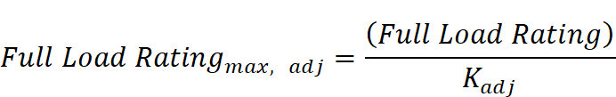
Packages not designed to operate at these conditions must have maximum adjusted Full Load and NPLV ratings. These ratings can be calculated, in kW/ton, using Equation 4-1 and Equation 4-2.
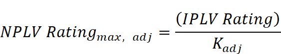
The values for the Full Load and IPLV Ratings are found in Table
4-4.


Where:
LvgCond = Full-load leaving condenser fluid temperature (°F)
LvgEvap = Full-load leaving evaporator fluid temperature (°F)
Where:
LvgEvap = Full-load leaving evaporator fluid temperature (°F)
The adjusted maximum adjusted Full Load and NPLV rating values are only applicable for centrifugal chillers meeting all of the following full-load design ranges:
1. Minimum Leaving Evaporator Fluid Temperature: 36°F
2. Maximum Leaving Condenser Fluid Temperature: 115°F
3. LIFT ≥ 20°F and ≤ 80°F
Centrifugal chillers designed to operate outside of these ranges are not covered by this exception and therefore have no minimum efficiency requirements.
Exception 2 is for positive displacement (air- and water-cooled) chillers with a leaving evaporator fluid temperature higher than 32°F, which shall show compliance with Table 4-3 when tested or certified with water at standard rating conditions, per the referenced test procedure.
Exception 3 is for equipment primarily serving refrigerated warehouses or commercial refrigeration systems. These systems must comply with the efficiency requirements of Energy Standards §120.6(a) or (b). For more information see Chapter 10.
To comply, equipment specified in the plans and specifications must meet the minimum standards mandated in that section. Manufacturers of equipment not regulated by the Appliance Efficiency Regulations are not required to certify their equipment to the Energy Commission; it is the responsibility of the designer and contractor to specify and install equipment that complies.
To verify certification, use one of the following options:
1. The Energy Commission’s website includes listings of energy efficient appliances for several appliance types. The website address is http://www.energy.ca.gov/appliances. The Energy Commission’s Hotline staff can provide further assistance, at 1-800-772-3300 or (916) 654-5106, if appliance information is not found on the website.
2. The complete appliance database can be downloaded. This requires spreadsheet programs compatible with Microsoft Excel. To use the data, a user must download the database file (or files), download a brand file and a manufacturer file and then decompress the files. Next, the user will need to download a description file that provides details on what is contained in each of the data fields. With these files, and using database software, the data can be sorted and manipulated.
3. The Air Conditioning, Heating and Refrigeration Institute (AHRI) Directory of Certified Products can be used to verify certification of air-conditioning equipment. This information is available on their website at www.ahrinet.org.

The Energy Standards discourage use of electric resistance heating when an alternative method of heating is available. In the case of a heat pump, these systems may contain electric resistance heat strips which act as a supplemental heating source. If this system is used then controls must be put in place that prevents use of the electric resistance when the heating load can be satisfied with the heat pump alone. This includes the requirement that the thermostat must be able to provide step up controls that will incrementally adjust the indoor temperature setting so that the heat pump can gradually raise the temperature until the final desired indoor temperature is reached. Also, the controls must set a “cut-on” temperature for compressor heating which is higher than the “cut-on” temperature for electric resistance heating, and the “cut-off temperature for compression heating is higher than the “cut-off” temperature for electric resistance heating.
Exceptions exist for this requirement:
1. If the electric resistance heating is for defrost, star-ups and follows the room thermostat set points (or another control mechanism designed to preclude the unnecessary operation).
2. If the heat pump is a room air-conditioner heat pump.
§110.2(c) and §120.2(b)4
When a central energy management control system (EMCS) is not included in the design of the HVAC system, then a thermostat with setback capabilities must be installed. The requirement is for all unitary heating or cooling systems to have a thermostat that is capable of at least 4 set points in a 24 hour period. In the case of a heat pump, the control requirements of Section 4.2.4 must also be met. 'In addition, per §120.2(b)4, the thermostats on all unitary single zone, air conditioners, heat pumps, must comply with the requirements of Reference Joint Appendix JA5, also known as the Occupant Controlled Smart Thermostats, which are capable of receiving demand response signals in the event of grid congestion and shortages during high electrical demand periods.
There are two exceptions to §120.2(b)4 Occupant Controlled Smart Thermostats:
1. Systems serving zones that must have constant temperatures to protect a process or product (e.g. a laser laboratory or a museum).
2. The following HVAC systems do not need to comply with the setback or Occupant Controlled Smart Thermostat requirement:
a. Gravity gas wall heaters
b. Gravity floor heaters
c. Gravity room heaters
d. Non-central electric heaters
e. Fireplaces or decorative gas appliance
f. Wood stoves
g. Room air conditioners
h. Room heat pumps
i. Packaged terminal air conditioners
j. Packaged terminal heat pumps
Forced air gas- and oil-fired furnaces with input ratings ≥225,000 Btu/h are required to have controls and designs that limit their standby losses:
1. They must have either an intermittent ignition or interrupted device (IID). Standing pilot lights are not allowed.
2. They must have either power venting or a flue damper. A vent damper is an acceptable alternative to a flue damper for furnaces where combustion air is drawn from the conditioned space.
Any furnace with an input rating ≥225,000 Btu/h that is not located within the conditioned space must have jacket losses not exceeding 0.75 percent of the input rating. This includes electric furnaces as well as fuel-fired units.
All open and closed circuit cooling towers with rated capacity of 150 tons or greater must have a control system that maximizes the cycles of concentration based on the water quality conditions based on either conductivity or flow. If the controls system is conductivity based then the system must automate bleed and chemical feed based on conductivity. The installation criteria for the conductivity controllers must be in accordance with the manufacturer’s specifications in order to maximize accuracy. If the control system is flow based, then the system must be automated in proportion to metered makeup volume, metered bleed volume, recirculating pump run time or bleed time.
The makeup water line must be equipped with an analog flow meter that is either wired or wireless and an overflow alarm to prevent overflow of the sump in the event of water valve failure. The alarm system may send an audible signal or an alert through an EMCS.
Drift eliminators are of a louvered or comb like design that is installed at the top of the cooling tower to capture water particles that become entrained in the air stream. These drift eliminators are now required to achieve drift reduction to 0.002 percent of the circulated water volume for counter-flow towers and 0.005 percent for cross-flow towers.
Additionally, maximum achievable cycles of concentration must be documented based on local water supply (which is reported annually by the local utility) and Langelier Saturation Index (LSI) of 2.5 or less. A calculator that is approved by the Energy Commission must be used in this process and the compliance document must be reviewed and approved by the Professional Engineer (P.E.) of record The Energy Commission’s website includes an approved LSI calculator in the form of an excel file. The website address is http://www.energy.ca.gov/title24/2013standards/documents/maximum_cycles_calculator.xls
Pilot lights are prohibited in:
1. Fan type central furnaces. This includes all space-conditioning equipment that distributes gas-heated air through duct work §110.5(a). This prohibition does not apply to radiant heaters, unit heaters, boilers or other equipment that does not use a fan to distribute heated air.
2. Household cooking appliances unless the appliance does not have an electrical connection, and the pilot consumes less than 150 Btu/h §110.5(b).
3. Pool and spa heaters §110.5(c)(d) respectively.
Example 4-1
Question
If a 15 ton (180kBtuh) air-cooled packaged AC unit with a gas furnace rated at 260,000 Btu/h maximum heating capacity has an EER of 10.9, an IEER of 11.2, and a heating thermal efficiency of 78 percent, does it comply?
Answer
No. The cooling side complies because both the EER and IEER exceed the requirements of Table 4-1 (11.0-0.2=10.8 EER and 11.2-0.2=11.0 IEER for a 15 ton unit). The EER and IEER in this table are for units with electric heat. Footnote b reduces the required EER and IEER by 0.2 for units with heating sections other than electric resistance heat. With gas heat, an EER of 10.9 (>10.8) and an IEER of 11.2 (>11.0), this unit complies. Note that the 0.2 deduction provided in Table 4-1 and Table 4-2 compensate for the higher fan power required to move air over the heat exchangers for fuel-fired heaters.
From Table 4-10, the heating efficiency must be at least 80 percent thermal efficiency. This unit has a 78 percent thermal efficiency (<80%); therefore the unit does not comply.
Example 4-2
Question
A 500,000 Btu/h gas-fired boiler with high/low firing has a full load combustion efficiency of 82 percent, 78 percent thermal efficiency and a low-fire combustion efficiency of 80 percent. Does the unit comply?
Answer
No. Per Table 4-11, the thermal efficiency must be greater than 80 percent. This boiler’s thermal efficiency is 78percent (<80%) so it doesn’t comply.
Example 4-3
Question
A 300 ton centrifugal chiller is designed to operate at 44°F chilled water supply, 90°F condenser water return and 3 gpm/ton condenser water flow. What is the maximum allowable full load kW/ton and NPLV?
Answer
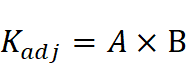
As the chiller is centrifugal and is designed to operate at a condition different from AHRI Standard 550/590 standard rating conditions, the appropriate efficiencies can be calculated using the Kadj equations.
From Table 4-4 (Equipment Type: Water Cooled, Electrically Operated, Centrifugal; Size Category: ≥ 300 tons and < 600 tons), this chiller at AHRI rating conditions has a maximum full load efficiency of 0.576 kW/ton and a maximum IPLV of 0.549 kW/ton for Path A and a maximum full load efficiency of 0.600 kW/ton and a maximum IPLV of 0.400 kW/ton for Path B.
The Kadj is calculated as follows:
LIFT = LvgCond – LvgEvap = 90F-44F = 46F
A = (0.00000014592 x (46)4) – (0.0000346496 x (46)3 )+ (0.00314196 x (46)2) – (0.147199 x *(46)) + 3.9302=1.08813
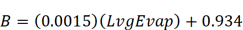
B = (0.0015 x 44) + 0.934 = 1.000
Kadj=A x B=1.08813
For compliance with Path A, the maximum Full load kW/ton = 0.576 / 1.08813 = 0.529 kW/ton and the maximum NPLV= 0.549 / 1.08813 = 0.505 kW/ton
For compliance with Path B the maximum Full load kW/ton = 0.600 / 1.08813 = 0.551 kW/ton and the maximum NPLV= 0.400 / 1.08813 = 0.388 kW/ton
To meet the mandatory measures of 4.2.2 (Energy Standards §110.2) the chiller can comply with either the Path A or Path B requirement (footnote b in Table 4-4). To meet the prescriptive requirement of 4.6.2.8 (Energy Standards §140.4(i)) the chiller would have to meet or exceed the Path B requirement.
Example 4-4
Question
A 300 ton water cooled chiller with a screw compressor that serves a thermal energy storage system is designed to operate at 34°F chilled water supply, 82°F condenser water supply and 94°F condenser water return, does it have a minimum efficiency requirement and if so, what is the maximum full load kW/ton and NPLV?
Answer
As the chiller is positive displacement (screw and scroll compressors are positive displacement) and is designed to operate at a chilled water temperature above 32°F it does have a minimum efficiency requirement per 4.2.2 (Exception 2 to §110.2(a)). From Table 4-4 (Equipment Type: Water Cooled, Electrically Operated, Positive Displacement; Size Category: ≥ 300 tons) this chiller at AHRI rating conditions has a maximum full load efficiency of 0.620 kW/ton and a maximum IPLV of 0.540 kW/ton for Path A and a maximum full load efficiency of 0.639 kW/ton and a maximum IPLV of 0.490 kW/ton for Path B.
The Kadj is calculated as follows:
LIFT = LvgCond – LvgEvap = 94F-34F = 60F
A =
(0.00000014592 x (60)4) – (0.0000346496 x (60)3 )+ (0.00314196 x (60)2) –
(0.147199 x *(60)) + 3.9302=0.81613
B = (0.0015 x 34) + 0.934 =
0.98500
Kadj=A x B=0.80388
For compliance with Path A, the maximum Full load kW/ton = 0.620 / 0.80388 = 0.771 kW/ton and the maximum NPLV= 0.540 / 0.80388 = 0.672 kW/ton. For compliance with Path B the maximum Full load kW/ton = 0.639 / 0.80388 = 0.795 kW/ton and the maximum NPLV= 0.490 / 0.80388 = 0.610 kW/ton. To meet the mandatory measures of 4.2.2 (Energy Standards §110.2) the chiller can comply with either the Path A or Path B requirement (footnote b in Table 4-4). To meet the prescriptive requirement of 4.6.2.8 (Energy Standards §140.4(i)) the chiller would have to meet or exceed the Path B requirement.
Example 4-5
Question
Are all cooling towers required to be certified by CTI?
Answer
No. Per footnote d in Table 4-7, field-erected cooling towers are not required to be certified. Factory-assembled towers must either be CTI-certified or have their performance verified in a field test (using ATC 105) by a CTI-approved testing agency. Furthermore only base models need to be tested; options in the air-stream, like access platforms or sound traps, will derate the tower capacity by 90 percent of the capacity of the base model or the manufacturer’s stated performance, whichever is less.
Example 4-6
Question
Are there any mandatory requirements for a water-to-water plate-and-frame heat exchanger?
Answer
Yes, Table 4-6 requires that it be rated per ANSI/AHRI 400. This standard ensures the accuracy of the ratings provided by the manufacturer.
A commercial boiler is a type of boiler with a capacity (rated maximum input) of 300,000 Btu per hour (Btu/h) or more and serving a space heating or water heating load in a commercial building.
A. Combustion air positive shut-off shall be provided on all newly installed commercial boilers as follows:
1. All boilers with an input capacity of 2.5 MMBtu/h (2,500,000 Btu/h) and above, in which the boiler is designed to operate with a non-positive vent static pressure. This is sometimes referred to as natural draft or atmospheric boilers. Forced draft boilers, which rely on a fan to provide the appropriate amount of air into the combustion chamber, are exempt from this requirement.
2. All boilers where one stack serves two or more boilers with a total combined input capacity per stack of 2.5 MMBtu/h (2,500,000 Btu/h). This requirement applies to natural draft and forced draft boilers.
Combustion air positive shut-off is a means of restricting air flow through a boiler combustion chamber during standby periods, used to reduce standby heat loss. A flue damper and a vent damper are two examples of combustion air positive shut-off devices.
Installed dampers can be interlocked with the gas valve so that the damper closes and inhibits air flow through the heat transfer surfaces when the burner has cycled off, thus reducing standby losses. Natural draft boilers receive the most benefit from draft dampers because they have less resistance to airflow than forced draft boilers. Forced draft boilers rely on the driving force of the fan to push the combustion gases through an air path that has relatively higher resistance to flow than in a natural draft boiler. Positive shut-off on a forced draft boiler is most important on systems with a tall stack height or multiple boiler systems sharing a common stack.
B. Boiler combustion air fans with motors 10 horsepower or larger shall meet one of the following for newly installed boilers:
1. The fan motor shall be driven by a variable speed drive, or
2. The fan motor shall include controls that limit the fan motor demand to no more than 30 percent of the total design wattage at 50 percent of design air volume.
Electricity savings result from run time at part-load conditions. As the boiler firing rate decreases, the combustion air fan speed can be decreased.
C. Newly installed boilers with an input capacity of 5 MMBtu/h (5,000,000 Btu/h) and greater shall maintain excess (stack-gas) oxygen concentrations at less than or equal to 5.0 percent by volume on a dry basis over firing rates of 20 percent to 100 percent. Combustion air volume shall be controlled with respect to firing rate or measured flue gas oxygen concentration. Use of a common gas and combustion air control linkage or jack shaft is prohibited. Boilers with steady state full-load thermal efficiency 85 percent or higher are exempt from this requirement.
One way to meet this requirement is with parallel position control. Boilers mix air with fuel (usually natural gas although sometimes diesel or oil) to supply oxygen during combustion. Stoichiometric combustion is the ideal air/fuel ratio where the mixing proportion is correct, the fuel is completely burned, and the oxygen is entirely consumed. Boilers operate most efficiently when the combustion air flow rate is slightly higher than the stoichiometric air-fuel ratio. However, common practice almost always relies on excess air to ensure complete combustion, avoid unburned fuel and potential explosion, and prevent soot and smoke in the exhaust. Excess air has a penalty, which is increased stack heat loss and reduced combustion efficiency.
Parallel positioning controls optimize the combustion excess air to improve the combustion efficiency of the boiler. It includes individual servo motors allowing the fuel supply valve and the combustion air damper to operate independently of each other. This system relies on preset fuel mapping (i.e., a pre-programmed combustion curve) to establish proper air damper positions (as a function of the fuel valve position) throughout the full range of burner fire rate. Developing the combustion curve is a manual process, performed in the field with a flue-gas analyzer in the exhaust stack, determining the air damper positions as a function of the firing rate/fuel valve position. Depending on type of burner, a more consistent level of excess oxygen can be achieved with parallel position compared to single-point positioning control, since the combustion curve is developed at multiple points (firing rates), typically 10 to 25 points. Parallel positioning controls allow excess air to remain relatively low throughout a burner’s firing range. Maintaining low excess air levels at all firing rates provides significant fuel and cost savings while still maintaining a safe margin of excess air to insure complete combustion.