This section addresses the requirements for space cooling equipment.
The efficiency of most cooling equipment is regulated by NAECA (the federal appliance standard) and the California Appliance Efficiency Regulations. These regulations are not contained in the Energy Standards but are referenced in §110.1. The energy efficiency of larger equipment is regulated by §110.2(a). See the Nonresidential Compliance Manual for information on larger equipment.
A. Central, Single Phase Air Conditioners and Air Source Heat Pumps (under 65,000 Btu/h)
The central, single-phase air conditioners and air source heat pumps that are most commonly installed in residences have a capacity less than 65,000 Btu/h. The Appliance Efficiency Regulations for this equipment require minimum seasonal energy efficiency ratios (SEER).
The SEER of all new central, single-phase air conditioners and air source heat pumps with output less than 65,000 Btu/h shall be certified to the Energy Commission to have values no less than the values 'listed below in Table 4-6.
|
Appliance |
Type |
SEER Eff 1/1/2015 |
EER Eff 1/1/2015 |
|
Central |
Split System <45,000 Btuh |
14 |
12.2 |
|
Split System ≥45,000 Btuh |
14 |
11.7 | |
|
Single Package |
14 |
11.0 | |
|
Central Air Source Heat Pumps |
Split System |
14 |
NR |
|
Single Package |
14 |
NR | |
|
Space Constrained Air Conditioner |
Split System |
12 |
NR |
|
Single Package |
12 |
NR | |
|
Space-Constrained Heat Pump |
Split System |
12 |
NR |
|
Single Package |
12 |
NR | |
|
Small-Duct, High-Velocity Air Conditioner |
All |
12 |
NR |
|
Small-Duct, High-Velocity Heat Pump |
All |
12 |
NR |
|
1. Central split system air conditioners and central single package air conditioners installed on or after January 1st, 2015 must comply with the minimum SEER and EER requirements of this table regardless of date of manufacturer. | |||
Source: California Appliance Efficiency Regulations, Title 20, Table C-2 and Federal Appliance Standards (NAECA)
A. Other Air Conditioners and Heat Pumps
Appliance Efficiency Regulations
The current Appliance Efficiency Regulations for three-phase models, larger capacity central air conditioners and heat pumps, and all room air conditioners and room air conditioner heat pumps shall be certified to the Energy Commission by the manufacturer to have values no less than the values 'listed in Table 4-7.
|
Equipment Type |
Size Category |
SEER or EER |
|
Central Air Conditioners |
< 65,000 Split System* |
13.0 SEER |
|
< 65,000 Single Packaged* |
13.0 SEER | |
|
≥65,000 Btu/h but <135,000 Btu/h |
11.21 EER 11.02 EER | |
|
≥135,000 Btu/h but <240,000 Btu/h |
11.01 EER 10.82 EER | |
|
≥240,000 Btu/h but <760,000 Btu/h |
10.01 EER 9.82 EER | |
|
Central Air Source Heat Pumps |
< 65,000 Split System* |
13.0 SEER |
|
< 65,000 Single Packaged* |
13.0 SEER | |
|
≥ 65,000 Btu/h but <135,000 Btu/h |
11.01 EER 10.82 EER | |
|
≥135,000 Btu/h but <240,000 Btu/h |
10.61 EER 10.42 EER | |
|
≥240,000 Btu/h but <760,000 Btu/h |
9.51 EER 9.32 EER | |
|
Central Water Source Heat Pumps |
< 17,000 Btu/h |
11.2 EER |
|
≥ 17,000 Btu/h and < 65,000 Btu/h |
12.0 EER | |
|
≥ 65,000 Btu/h and < 135,000 Btu/h |
11.9 EER | |
|
≥ 135,000 Btu/h and < 240,000 Btu/h |
12.3 EER | |
|
≥ 240,000 Btu/h and < 760,000 Btu/h |
12.2 EER | |
|
Water-Cooled Air Conditioners |
< 17,000 Btu/h |
12.1 EER |
|
< 17,000 < 65,000 Btu/h |
12.1 EER | |
|
≥ 65,000 Btu/h and < 135,000 Btu/h |
12.13 EER | |
|
≥ 135,000 Btu/h and < 240,000 Btu/h |
12.53 EER | |
|
≥ 240,000 Btu/h and < 760,000 Btu/h |
12.43 EER | |
|
* Three-phase models only 1 Applies to equipment that has electric resistance heat or no heating. 2 Applies to equipment with all other heating-system types that are integrated into the unitary equipment. 3. Deduct 0.2 from the required EER for units with heating sections other than electric resistance heat. | ||
Source: California Appliance Efficiency Regulations Table C-3, C-4
|
Equipment Type |
Size Category (Input) |
Minimum Efficiency |
|
Room Air Conditioners,
|
< 6,000 Btu/h |
11.0 EER |
|
³ 6,000 Btu/h and - 7,999 Btu/h |
11.0 EER | |
|
³ 8,000 Btu/h and -13,999 Btu/h |
10.9EER | |
|
³ 14,000 Btu/h and - 19,999 Btu/h |
10.7 EER | |
|
³ 20,000 Btu/h and 27,999 Btu/h |
9.4 EER | |
|
³ 28,000 Btu/h |
9.0 EER | |
|
Room Air Conditioners,
|
< 6,000 Btu/h |
10.0 EER |
|
³ 6,000 Btu/h and - 7,999 Btu/h |
10.0 EER | |
|
³ 8,000 Btu/h and - 10,999 Btu/h |
9.6 EER | |
|
³ 11,000 Btu/h and - 13,999 Btu/h |
9.5 EER | |
|
³ 14,000 Btu/h and - 19,999 Btu/h |
9.3 EER | |
|
³ 20,000 Btu/h |
9.4 EER | |
|
Room Air Conditioner Heat
Pumps |
< 20,000 Btu/h |
9.8 EER |
|
³ 20,000 Btu/h |
9.3 EER | |
|
Room Air Conditioner Heat Pumps Without Louvered Sides |
< 14,000 Btu/h |
9.3 EER |
|
³ 14,000 Btu/h |
8.7 EER | |
|
Casement-Only Room Air Conditioner |
All Capacities |
9.5 EER |
|
Casement-Slider Room Air Conditioner |
All Capacities |
10.4 EER |
|
PTAC (cooling mode) Newly Constructed or Newly Conditioned Buildings or |
All Capacities |
14.0-(0.300 x Cap/1000) = EER |
|
PTAC (cooling mode) Replacements |
All Capacities |
10.9-(0.213 x Cap/1000) = EER |
|
PTHP (cooling mode) Newly Constructed or newly conditioned buildings or Additions |
All Capacities |
14.0-(0.300 x Cap/1000) = EER |
|
PTHP (cooling mode) Replacements |
All Capacities |
10.8-(0.213 x Cap/1000) = EER |
|
SPVAC (cooling mode) |
< 65,000 Btu/h |
10.0 EER |
|
≥ 65,000 Btu/h and < 135,000 Btu/h |
10.0 EER | |
|
≥ 135,000 Btu/h and < 240,000 Btu/h |
10.0 EER | |
|
SPVHP (cooling mode) |
< 65,000 Btu/h |
10 EER |
|
≥ 65,000 Btu/h and < 135,000 Btu/h |
10 EER | |
|
≥ 135,000 Btu/h and < 240,000 Btu/h |
10 EER | |
|
Cap. = Cooling Capacity (Btu/hr) | ||
|
Note: Including room air conditioners and room air conditioner heat pumps, package terminal air conditioners (PTAC), package terminal heat pumps (PTHP), single-package vertical air conditioners (SPVAC), and heat pumps (SPVHP). | ||
Source: California Appliance Efficiency Regulations Title 20, Table B-2, the Energy Standards Table 110.2-E
§150.0(j)2 and 3, §150.0(m)9 Two refrigerant lines connect the indoor and outdoor units of split-system air conditioners and heat pumps: the liquid line (the smaller diameter line) and the suction line (the larger diameter line).
If the liquid line is at an elevated temperature relative to outdoor and indoor temperatures, it should not be insulated. In those areas, heat escaping from it is helpful. When the liquid line runs through the attic, the attic temperature is higher than the liquid line temperature, so liquid lines running through attics should be insulated to reduce heat transfer from the surrounding environment into the refrigeration system.
The suction line carries refrigerant vapor that is cooler than ambient in the summer and (with heat pumps) warmer than ambient in the winter. This line must be insulated to the required thickness (in inches) as specified in Table 4-9.
|
Fluid Temperature Range (oF) |
Conductivity Range (in Btu-inch per hour per square foot per oF |
Insulation Mean Rating Temperature(oF) |
Nominal Pipe Diameter (in inches) | |||||
|
1 and less |
1 to <1.5 |
1.5 to <4 |
4 to <8 |
8 and larger | ||||
|
Insulation Thickness Required (in inches) | ||||||||
|
Space cooling systems suction line | ||||||||
|
40-60 |
0.21-0.27 |
75 |
0.75 |
0.75 |
1.0 |
1.0 |
1.0 | |
|
Below 40 |
0.20-0.26 |
50 |
1.0 |
1.5 |
1.5 |
1.5 |
1.5 | |
|
From Table 120.3-A of the Energy Standards | ||||||||
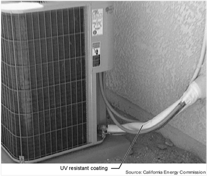
Insulation used for refrigerant suction lines located outside a condition space, must include a Class I or Class II vapor retarder. The vapor retarder and insulation must be protected from physical damage, UV deterioration, and moisture with a covering that can be removed for equipment maintenance without destroying the insulation. Insulation is typically protected by aluminum, sheet metal jacket, painted canvas, or plastic cover. Adhesive tape should not be used as insulation protection as removal of the tape will damage the integrity of the original insulation during preventive maintenance. See §150.0(j) 3 and Source: Airex Manufacturing Inc.
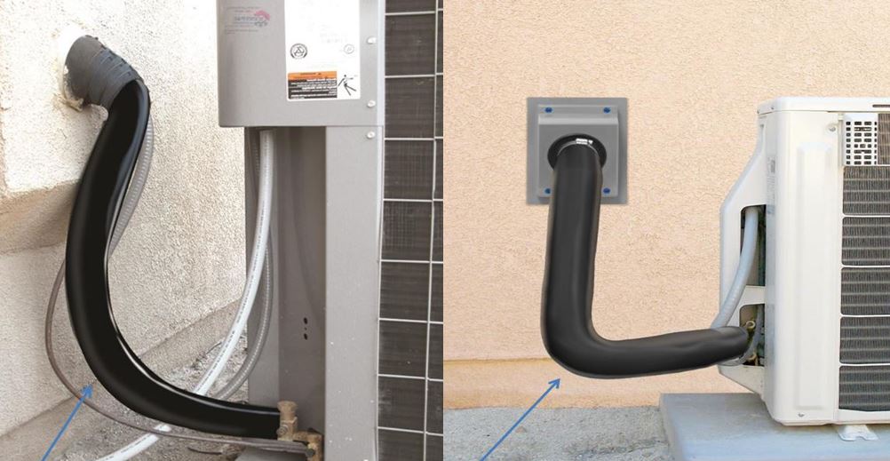
Source: Airex Manufacturing Inc.
Any obstruction of the airflow through the outdoor unit of an air conditioner or heat pump lowers efficiency. Dryer vents are prime sources for substances that clog outdoor coils and sometimes discharge substances that can cause corrosion. Therefore, condensing units shall not be placed within 5 feet of a dryer vent. Regardless of location, condenser coils should be cleaned regularly in all homes. The manufacturer installation instructions may include requirements for minimum horizontal and vertical distance to surrounding objects that should be met if greater than the minimum distance required by the Energy Standards.
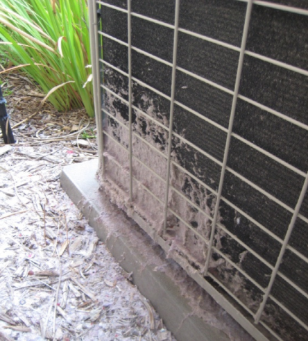
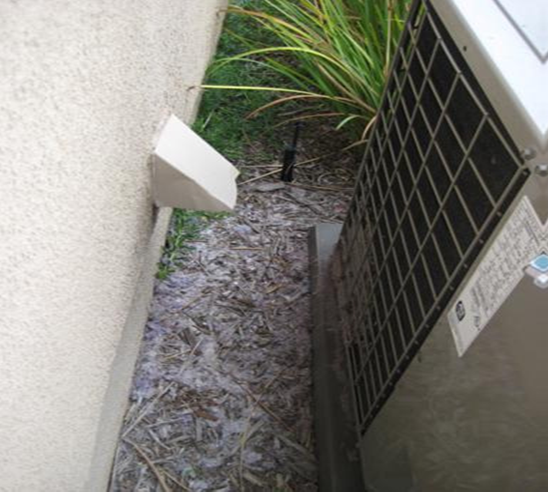
Source: California Energy Commission
Liquid line filter driers are components of split system air-conditioners and split system heat pumps that are installed in the refrigerant line to remove noncondensables, like moisture and particles, from the refrigerant stream. These noncondensables may appear in the refrigerant line due to improper charging procedures and result in reduced efficiency and capacity for the air conditioner. If required by manufacturer’s instructions, liquid line filter dryers must be installed. Sometimes, liquid line filter dryers are preinstalled by manufacturers within condensing units, which makes it difficult for technicians to access. Because of this difficulty, manufacturers have begun changing this practice by installing liquid line filter dryers outside condensers, so that they can be easily serviced by technicians and more easily verified by HERS Raters.
The quality of installation is important to the effectiveness of the liquid line filter dryer, as some liquid line filter dryers can be installed without regard to the direction of refrigerant flow. Heat pumps, for example, allow refrigerant flow in both directions. However, in other air conditioners where refrigerant flow occurs in only one direction, the orientation of the liquid line filter dryer will matter.
Similar to heating equipment, the Energy Standards do not set limits on the size of cooling equipment, but they do require that cooling loads be calculated for new cooling systems. Avoid oversizing the cooling components since oversizing may adversely affect the efficiency of the system. Ducts must be sized correctly, otherwise the system airflow rate may be restricted, adversely affecting the efficiency of the system and preventing the system from meeting the mandatory minimum airflow rate requirements.
The outdoor design conditions for load calculations must be selected from Reference Joint Appendix JA2, Table 2-3, using values no greater than the “1.0 percent cooling dry bulb” and “mean coincident wet bulb” values listed. The indoor design temperature for cooling load calculations must be 75°F. Acceptable load calculation procedures include methods described in:
1. The ASHRAE Handbook – Equipment.
2. The ASHRAE Handbook – Applications.
3. The ASHRAE Handbook – Fundamentals.
4. The SMACNA Residential Comfort System Installation 'Manual.
5. ACCA Manual J.
Cooling load calculations must be submitted with compliance documentation when requested by the building department. The load calculations may be prepared by 1) a mechanical engineer, 2) the mechanical contractor who is installing the equipment or 3) someone who is qualified to do so in the State of California according to Division 3 of the Business and Professions Code
Space-conditioning systems that use forced air ducts to cool occupiable space shall have a hole for the placement of a static pressure probe (HSPP) or permanently installed static pressure probe (PSPP) installed downstream from the evaporator coil.
The HSPP or PSPP must be installed in the required location, in accordance with the specifications detailed in Reference Residential Appendix RA3.3. The HSPP or PSPP is required to promote system airflow measurement when using devices/procedures that depend on supply plenum pressure measurements. The HSPP or PSPP allows HERS Raters to perform the required diagnostic airflow testing in a nonintrusive manner, by eliminating the necessity for the Raters to drill holes in the supply plenum for placement of pressure measurement probes.
The size and placement of the HSPP/PSPP shall be in accordance with RA3.3.1.1 and shall be verified by a HERS Rater. In the event that the HSPP/PSPP cannot be installed as shown in Figure RA3.3-1, due to the configuration of the system or that the location is not accessible, an alternative location may be provided that can accurately measure the average static pressure in the supply plenum. If an alternative location cannot be provided then the HSPP/PSPP is not required to be installed. The HERS rater will verify this. Not installing an HSPP/PSPP will limit the airflow measurement method to either a powered flow-hood or passive (traditional) flow hood.
When the mandatory measure for minimum system airflow rate is in effect (entirely new systems), there must be a hole in the supply plenum, provided by the installing contractor, for the placement of a static pressure probe (HSPP). Alternatively a permanently installed static pressure probe (PSPP) must be installed in the same location.
This requirement also applies when the plenum pressure matching method or the flow grid method of airflow measurement is used by either the installer or the rater to verify airflow in an altered system. The HSPP/PSPP must be installed by the installer, not the Rater.
See Air Distribution Ducts, Plenums, and Fans Section 4.4 for discussion regarding mandatory sizing/airflow requirements for ducted systems with cooling.

Prescriptive Component Package A, for air-cooled air conditioners and air-source heat pumps installed in Climate Zones 2 and 8 through 15, requires the installation of a measurement access hole (MAH), refrigerant charge verification (RCV), and minimum system airflow verification. The minimum system airflow installation and RCV must be performed by the installer and/or HERS Rater. The MAH provides a nonintrusive means of measuring return air temperature, which is a parameter important to the RCV process. The alternative to RCV by a HERS Rater is the installation of a refrigerant fault indicator display (§151(f)7Aia). When installing a fault indicator display, the installer must still perform a RCV.
Note: The refrigerant charge verification is discussed in greater detail later in Section 4.9.
The MAH provides a nonintrusive means for refrigerant charge verification by HERS Raters and other third-party inspectors. They eliminate the need for Raters/inspectors to drill holes into the installed air conditioning equipment enclosures for placement of the temperature sensors required by the refrigerant charge verification test procedures described in the Reference Residential Appendix RA3.2.
Installation of MAH must be performed by the installer of the air conditioner or heat pump equipment according to the specifications given in Reference Residential Appendix RA3.2.
The MAH feature consists of one 5/8-inch (16 mm) diameter hole in the return plenum, upstream from the evaporator coil. (See figure RA3.2-1 in Reference Residential Appendix RA3.2.)
Ducted forced air systems must comply with the minimum system airflow rate of greater than or equal to 350 cfm per ton when performing the refrigerant charge verification. The airflow is important when performing the refrigerant charge verification to validate the measured values for pressure and temperature. The correct airflow will also improve the performance of the air-conditioning equipment.
The airflow verification procedure is documented in Reference Residential Appendix RA3.3..
The prescriptive standards require that a HERS Rater verify that air-cooled air conditioners and air-source heat pumps have the correct refrigerant charge. The RCV procedures are documented in Reference Residential Appendix RA3.2, and RA1.2. RA2.4.4, and RA1.2. RA3.2.
Refrigerant charge refers to the actual amount of refrigerant present in the system. Excessive refrigerant charge (overcharge) reduces system efficiency and can lead to premature compressor failure. Insufficient refrigerant charge (undercharge) also reduces system efficiency and can cause compressors to overheat. Ensuring correct refrigerant charge can significantly improve the performance of air-conditioning equipment. Refrigerants are the working fluids in air-conditioning and heat-pump systems that absorb heat energy from one area (the evaporator),transfer, and reject it to another (the condenser).
Fault Indicator Display
The installation of a fault indicator display (FID) may be used as an alternative to the prescriptive requirement for HERS diagnostic testing of the refrigerant charge in air conditioners and heat pumps. The installation of a FID does not preclude the HVAC installer from having to properly charge the system with refrigerant. The FID provides real-time information to the building occupant about the status of the system refrigerant charge, metering device, and system airflow. The FID will monitor and determine the operating performance of air conditioners and heat pumps and provide visual indication to the system owner or operator if the refrigerant charge, airflow, or metering device performance of the system does not conform to approved target parameters for minimally efficient operation. Thus, if the FID signals the owner/occupant that the system requires service or repair, the occupant can immediately call for a service technician to make the necessary adjustments or repairs. A FID can provide significant benefit to the owner/occupant by alerting the owner/occupant to the presence of inefficient operation that could result in excessive energy use/costs over an extended period. A FID can also indicate system performance faults that could result in system component damage or failure if not corrected, thus helping the owner/occupant avoid unnecessary repair costs.
Fault indicator display technologies shall be installed in the factory or the field according to manufacturer's specifications. Reference Joint Appendix JA6 contains more information about FID technologies.
The presence of a FID on a system must be field-verified by a HERS Rater. See Reference Residential Appendix RA3.4.2 for the HERS verification procedure, which consists of a visual verification of the presence of the installed FID technology. The Rater must inspect to see that the visual indication display component of the installed FID technology is mounted adjacent to the thermostat of the split system. When the outdoor temperature is greater than 55°F, the rater must also observe that the system reports no system faults when the system is operated continuously for at least 15 minutes when the indoor air temperature returning to the air conditioner is at or above 70°F. When the outdoor temperature is below 55°F, the Rater must observe that the FID does a self-diagnosis and indicates that the sensors and internal processes are operating properly.
There are several options for receiving compliance credit related to the cooling system. These credits are available through the performance compliance method.
Air conditioner efficiencies are determined according to federal test procedures. The efficiencies are reported in terms of seasonal energy efficiency ratio (SEER) and energy efficiency ratio (EER). Savings can be achieved by choosing an air conditioner that exceeds the minimum efficiency requirements.
The EER is the full load efficiency at specific operating conditions. It is possible that two units with the same SEER can have different EERs. In cooling climate zones of California, for two units with a given SEER, the unit with the higher EER is more effective in saving energy. Using the performance compliance method, credit is available for specifying an air conditioner with an EER greater than 10 (See the compliance program vendor’s compliance supplement). When credit is taken for a high EER and/or SEER, field verification by a HERS Rater is required (See Reference Residential Appendix RA3.4).
It is mandatory that central forced air systems produce fan watt draws less than or equal to 0.58 watts/CFM and flow at least 350 CFM per nominal cooling ton. Performance compliance credits are available for demonstrating the installation of a high efficiency system with a lower fan wattage and/or higher airflow than the mandatory requirements. These credits can be achieved by selecting good duct design and can be assisted by a high efficiency fan. There are two possible performance compliance credits:
1. The performance compliance method allows the user’s proposed fan watt draw to be entered and credit earned if it is lower than the default of 0.58 watts per CFM of system airflow. To obtain this credit, the system airflow must meet the mandatory requirement of at least 350 CFM/ton of nominal cooling capacity.
2. The performance compliance method allows the user’s proposed airflow to be entered and credit earned if it is higher than the default of 350 CFM/ton of nominal cooling capacity. To obtain this credit, the fan watt draw must meet the mandatory requirement of no more than 0.58 watts per CFM of nominal cooling capacity.
After installation, the contractor must test the actual fan power and airflow of the system using the procedure in Reference Residential Appendix RA3.3, and show that it is equal or better than what was proposed in the compliance software analysis.
Field verification by a HERS Rater is required (See Reference Residential Appendix RA3.3).